
Chapter 17. Local Area Networking
Defining a Network
A network is a group of two or more computers that intelligently share hardware or software devices with each other. A network can be as small and simple as two computers that share a printer or as complex as the world’s largest network: the Internet.
Intelligently sharing means that each computer that shares resources with another computer or computers maintains control of that resource. Thus, a switchbox for sharing a single printer between two computers doesn’t qualify as a network device; because the switchbox—not the computers—handles the print jobs, neither computer knows when the other one needs to print, and print jobs can interfere with each other.
A shared printer, on the other hand, can be controlled remotely and can store print jobs from different computers on the print server’s hard disk. Users can change the sequence of print jobs, hold them, or cancel them. And, sharing of the device can be controlled through passwords, further differentiating it from a switchbox.
Virtually any storage or output device can be shared over a network, but the most common devices include the following:
• Printers
• Storage drives (hard disk, optical, or tape)
• Modems
• Fax machines
Entire drives or just selected folders can be shared with other users via the network.
In addition to reducing hardware costs by sharing expensive printers and other peripherals among multiple users, networks provide additional benefits to users:
• Multiple users can share access to software and data files.
• Electronic mail (email) can be sent and received.
• Multiple users can contribute to a single document using collaboration features.
• Remote-control programs can be used to troubleshoot problems or show new users how to perform a task.
• A single Internet connection can be shared among multiple computers.
Note
Networking is an enormous topic. For much more detailed information about client/server networking, corporate networking, and wide area networking, I recommend Upgrading and Repairing Networks from Que.
Types of Networks
Several types of networks exist, from small two-station arrangements, to networks that interconnect offices in many cities:
• Local area networks—The smallest office network is referred to as a local area network (LAN). A LAN is formed from computers and components in a single office or building. A LAN can also be built at home from the same components used in office networking.
• Wide area networks—LANs in different locations can be connected by high-speed fiber-optic, satellite, or leased phone lines to form a wide area network (WAN).
• The Internet—The World Wide Web is the most visible part of the world’s largest network, the Internet. Although many users of the Internet still use modems over a dialup connection rather than a LAN or WAN connection, any user of the Internet is a network user. The Internet is really a network of networks, all of which are connected to each other through the TCP/IP protocol. It’s a glorified WAN in many respects. Programs such as web browsers, File Transfer Protocol (FTP) clients, and email clients are some of the most common ways users work with the Internet.
• Intranets—Intranets use the same web browsers and other software and the same TCP/IP protocol as the public Internet, but intranets exist as a portion of a company’s private network. Typically, intranets comprise one or more LANs that are connected to other company networks, but, unlike the Internet, the content is restricted to authorized company users only. Essentially, an intranet is a private Internet.
• Extranets—Intranets that share a portion of their content with customers, suppliers, or other businesses, but not with the general public, are called extranets. As with intranets, the same web browsers and other software are used to access the content.
Note
Both intranets and extranets rely on firewalls and other security tools and procedures to keep their private contents private.
Requirements for a Network
Unless the computers that are connected know they are connected and agree on a common means of communication and what resources are to be shared, they can’t work together. Networking software is just as important as networking hardware because it establishes the logical connections that make the physical connections work.
At a minimum, each network requires the following:
• Physical (cable) and/or wireless (usually via radio-frequency) connections between computers.
• A common set of communications rules, known as a network protocol.
• Software that enables resources to be served to or shared with other PCs and that controls access to the shared resources. This can be in the form of a network operating system or NOS (such as older versions of Novell Netware) that runs on top of an operating system; however, current operating systems such as Windows, Mac OS X, and Linux also provide network sharing services, thus eliminating the need for a specialized NOS. A machine sharing resources is usually called a server.
• Resources that can be shared, such as printers, disk drives, optical drives, modems, and so on.
• Software that enables computers to access other computers sharing resources (servers). Systems accessing shared resources are usually called network clients. Client software can be in the form of a program or service that runs on top of an operating system. Current operating systems such as Windows, Mac OS X, and Linux include client software.
These rules apply both to the simplest and the most powerful networks, and all the ones in between, regardless of their nature. The details of the hardware and software you need are discussed more fully later in this chapter.
Client/Server Versus Peer Networks
Although every computer on a LAN is connected to every other computer, they do not necessarily all communicate with each other. There are two basic types of LANs, based on the communication patterns between the machines—client/server networks and peer-to-peer networks.
Client/Server Networks
On a client/server network, every computer has a distinct role, that of either a client or a server. A server is designed to share its resources among the client computers on the network. Typically, servers are located in secured areas, such as locked closets or data centers (server rooms), because they hold an organization’s most valuable data and do not have to be accessed by operators on a continuous basis. The rest of the computers on the network function as clients (see Figure 17.1).
Figure 17.1 The components of a client/server LAN.

A dedicated server computer often has faster processors, more memory, and more storage space than a client because it might have to service dozens or even hundreds of users at the same time. High-performance servers typically use from two to eight processors (and that’s not counting dual-core CPUs), have many gigabytes of memory installed, and have one or more server-optimized network interface cards, RAID (Redundant Array of Independent Drives) storage consisting of multiple drives, and redundant power supplies. Servers often run a special network operating system—such as Windows Server, Linux, Unix, or Novell NetWare—that is designed solely to facilitate the sharing of its resources. These resources can reside on a single server or on a group of servers. When more than one server is used, each server can “specialize” in a particular task (file server, print server, fax server, email server, and so on) or provide redundancy (duplicate servers) in case of server failure. For very demanding computing tasks, several servers can act as a single unit through the use of parallel processing.
A client computer typically communicates only with servers, not with other clients. A client system is a standard PC that is running an operating system such as Windows. Current operating systems contain client software that enables the client computers to access the resources that servers share. Older operating systems, such as Windows 3.x and DOS, required add-on network client software to join a network.
Peer-to-Peer Networks
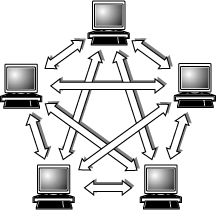
By contrast, on a peer-to-peer network, every computer is equal and can communicate with any other computer on the network to which it has been granted access rights (see Figure 17.2). Essentially, every computer on a peer-to-peer network can function as both a server and a client; any computer on a peer-to-peer network is considered a server if it shares a printer, a folder, a drive, or some other resource with the rest of the network. This is why you might hear about client and server activities, even when the discussion is about a peer-to-peer network. Peer-to-peer networks can be as small as two computers or as large as hundreds of systems. Although there is no theoretical limit to the size of a peer-to-peer network, performance, security, and access become a major headache on peer-based networks with more than 10 computers. In addition, Microsoft imposes a limit of only 5 or 10 concurrent client connections to computers running Windows. This means that a maximum of 10 (or fewer) systems will be able to concurrently access shared files or printers. The limit drops to only five concurrent connections if the host system is running most “home” versions of Windows such as XP Home or Vista/7 Home Basic (the Home Premium version of Windows Vista and 7 retain the limit of 10). When more than the allowed limit of 5 or 10 systems try to connect, the connection is denied and the client sees one of the following error messages:

Figure 17.2 The logical architecture of a typical peer-to-peer network.
Even though it is called a “Server” OS, Windows Home Server also has the same 10-connection limit as the non-Home client Windows versions. If you need a server that can handle more than 10 clients, I recommend using a Linux-based server OS (such as Ubuntu Server) or one of the professional Windows server products (such as Windows 2000 Server, Server 2003, Server 2008, Essential Business Server, or Small Business Server).
Peer-to-peer networks are more common in small offices or within a single department of a larger organization. The advantage of a peer-to-peer network is that you don’t have to dedicate a computer to function as a file server. Instead, every computer can share its resources with any other. The potential disadvantages to a peer-to-peer network are that typically less security and less control exist because users normally administer their own systems, whereas client/server networks have the advantage of centralized administration.
Comparing Client/Server and Peer-to-Peer Networks
Client/server LANs offer enhanced security for shared resources, greater performance, increased backup efficiency for network-based data, and the potential for the use of redundant power supplies and RAID drive arrays. Client/server LANs also have a much greater cost to purchase and maintain. Table 17.1 compares client/server and peer-to-peer server networking.
Table 17.1 Comparing Client/Server and Peer-to-Peer Networking


Network Architecture Overview
The architecture on which you choose to base your network is the single most important decision you make when setting up a local area network. The architecture defines the speed of the network, the medium access control mechanism it uses, the types of cables you can use, the network interface adapters you must buy, and the adapter drivers you install in the network client software.
The Institute of Electrical and Electronic Engineers (IEEE) has defined and documented a set of standards for the physical characteristics of both collision-detection and token-passing networks. These standards are known as IEEE 802.3 (Ethernet) and IEEE 802.5 (Token-Ring), respectively. IEEE 802.11 (Wi-Fi) defines wireless versions of Ethernet.
Note
Be aware, however, that the colloquial names Ethernet and Token-Ring actually refer to earlier versions of these architectures, on which the IEEE standards were based. Minor differences exist between the frame definitions for true Ethernet and true IEEE 802.3. In terms of the standards, IBM’s 16Mbps Token-Ring products are an extension of the IEEE 802.5 standard.
New Token-Ring installations are very rare today and are not covered here.
The most common choice today for new networks is Ethernet (both wired and wireless). In rare cases, Token-Ring or ARCnet might be seen in some older installations. Network data-link architectures you might encounter are summarized in Table 17.2. The abbreviations used for the cable types are explained in the following sections.
Table 17.2 LAN Architecture Summary

Wired Ethernet
With tens of millions of computers connected by Ethernet cards and cables, Ethernet is the most widely used data-link layer protocol in the world. You can buy Ethernet adapters from dozens of competing manufacturers, and most systems sold in the last decade incorporate one or more built-in Ethernet ports. Older adapters supported one, two, or all three of the cable types defined in the standard: Thinnet, Thicknet, and unshielded twisted pair (UTP). Current adapters support only UTP. Traditional Ethernet operates at a speed of 10Mbps, but the more recent standards push this speed to 100Mbps (Fast Ethernet) or 1,000Mbps (Gigabit Ethernet). Most newer desktop and even laptop systems now incorporate Gigabit Ethernet. In the future we will likely see 10 Gigabit Ethernet (also known as 10G Ethernet) appearing in PCs. 10G Ethernet runs at 10,000Mbps, and is used primarily in enterprise data centers and servers.
Note
Throughout the remainder of this chapter, be aware that discussion of older Ethernet solutions (such as those using Thicknet or Thinnet) as well as alternative networks (such as Token-Ring) are only included for reference. You will usually encounter those technologies only when working on older, existing networks. New network installations today normally use Gigabit, Fast, or Wireless Ethernet.
Fast Ethernet
Fast Ethernet requires adapters, hubs, switches, and UTP or fiber-optic cables designed to support the higher speed. Some early Fast Ethernet products supported only 100Mbps, but almost all current Fast Ethernet products are combination devices that run at both 10Mbps and 100Mbps, enabling backward compatibility with older 10Mbps Ethernet network hardware.
Note
Some specifications say that Fast Ethernet supports 200Mbps. This is because it normally runs in full-duplex mode (sends/receives data simultaneously), which gives it an effective speed of 200Mbps with both directions combined. Still, the throughput in any one direction remains the same 100Mbps. Full-duplex operation requires that all hardware in the connection, including adapters and switches, be capable of running in full-duplex and be configured to run in full-duplex (or automatically detect full-duplex signals).
Both the most popular form of Fast Ethernet (100BASE-TX) and 10BASE-T standard Ethernet use two of the four wire pairs found in UTP Category 5 cable. (These wire pairs are also found in CAT 5e, CAT 6, and CAT 7 cable.) An alternative Fast Ethernet standard called 100BASE-T4 uses all four wire pairs in UTP Category 5 cable, but this Fast Ethernet standard was never popular and is seldom seen today.
Gigabit Ethernet
Gigabit Ethernet also requires special adapters, hubs, switches, and cables. When Gigabit Ethernet was introduced, most installations used fiber-optic cables, but today it is far more common to run Gigabit Ethernet over the same Category 5 UTP cabling (although better CAT 5e or CAT6 is recommended) that Fast Ethernet uses. Gigabit Ethernet for UTP is also referred to as 1000BASE-T.
Unlike Fast Ethernet and standard Ethernet over UTP, Gigabit Ethernet uses all four wire pairs. Thus, Gigabit Ethernet requires dedicated Ethernet cabling; you can’t “borrow” two wire pairs for telephone or other data signaling with Gigabit Ethernet as you can with the slower versions. Most Gigabit Ethernet adapters can also handle 10BASE-T and 100BASE-TX Fast Ethernet traffic, enabling you to interconnect all three UTP-based forms of Ethernet on a single network.
Neither Fast Ethernet nor Gigabit Ethernet support the use of thin or thick coaxial cable originally used with traditional Ethernet, although you can interconnect coaxial cable–based and UTP-based Ethernet networks by using media converters or specially designed hubs and switches.
Wireless Ethernet
The most common forms of wireless networking are built around various versions of the IEEE 802.11 wireless Ethernet standards, including IEEE 802.11b, IEEE 802.11a, IEEE 802.11g, and IEEE 802.11n.
Wireless Fidelity (Wi-Fi) is a logo and term given to any IEEE 802.11 wireless network product certified to conform to specific interoperability standards. Wi-Fi certification comes from the Wi-Fi Alliance, a nonprofit international trade organization that tests 802.11-based wireless equipment to ensure it meets the Wi-Fi standard. To carry the Wi-Fi logo, an 802.11 networking product must pass specific compatibility and performance tests, which ensure that the product will work with all other manufacturers’ Wi-Fi equipment on the market. This certification arose from the fact that certain ambiguities in the 802.11 standards allowed for potential problems with interoperability between devices. By purchasing only devices bearing the Wi-Fi logo, you ensure that they will work together and not fall into loopholes in the standards.
Note
The Bluetooth standard for short-range wireless networking, covered later in this chapter, is designed to complement, rather than rival, IEEE 802.11–based wireless networks.
The widespread popularity of IEEE 802.11–based wireless networks has led to the abandonment of other types of wireless networking such as the now defunct HomeRF.
Note
Although products that are certified and bear the Wi-Fi logo for a particular speed (IEEE standard), such as 802.11g, are designed and tested to work together, many vendors of SOHO wireless networking equipment have started shipping devices that also feature proprietary technologies to raise the speed of the wireless network even further. Linksys called its proprietary solution SpeedBooster, for example, which is advertised as providing “performance increases of up to 30% from old 802.11g standards.” Just beware that most, if not all, of these vendor-specific solutions are not interoperable with solutions from other vendors. When different vendor-specific solutions are mixed on a single network, they use the slower standard all have in common to communicate with each other.
Wi-Fi
When the first 802.11b networking products appeared, compatibility problems existed due to certain aspects of the 802.11 standards being ambiguous or leaving loopholes. A group of companies formed an alliance designed to ensure that their products would work together, thus eliminating any ambiguities or loopholes in the standards. This was originally known as the Wireless Ethernet Compatibility Alliance (WECA) but is now known simply as the Wi-Fi Alliance (www.wi-fi.org). In the past, the term Wi-Fi has been used as a synonym for IEEE 802.11b hardware. However, because the Wi-Fi Alliance now certifies other types of 802.11 wireless networks (802.11a and 802.11g, for example), the term Wi-Fi should always be accompanied by the frequency band (as in Wi-Fi 2.4GHz band) to make it clear which products will work with the device. Currently, the alliance has certified products that meet the final versions of the 802.11b, 802.11a, and 802.11g standards. The Wi-Fi Alliance also certifies products that meet the specifications of the Draft 2.0 or later versions of the 802.11n standard.
Caution
Dual-band hardware can access the 802.11a, 802.11b, and 802.11g flavors of Wi-Fi. 802.11n hardware can also connect to 802.11b and 802.11g networks, and some implementations of 802.11n can also connect to 802.11a networks.
Be sure you find out which flavor of Wi-Fi is in use in a particular location to determine whether you can connect to it.
The Wi-Fi Alliance currently uses a color-coded certification label to indicate the standard(s) supported by a particular device. Figure 17.3 shows the most common versions of the label, along with the official IEEE standard(s) that the label corresponds to: 802.11a (orange background); 802.11b (dark blue background); 802.11g (lime green background); 802.11n (violet background).
Figure 17.3 The Wi-Fi Alliance’s certification labels for Wi-Fi–compliant 802.11 hardware.

IEEE 802.11b
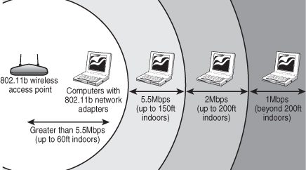
IEEE 802.11b (Wi-Fi, 2.4GHz band–compliant, also known as Wireless-B) wireless networks run at a maximum speed of 11Mbps, about the same as 10BASE-T Ethernet (the original version of IEEE 802.11 supported data rates up to 2Mbps only). 802.11b networks can connect to conventional Ethernet networks or be used as independent networks, similar to other wireless networks. Wireless networks running 802.11b hardware use the same 2.4GHz spectrum that many portable phones, wireless speakers, security devices, microwave ovens, and the Bluetooth short-range networking products use. Although the increasing use of these products is a potential source of interference, the short range of wireless networks (indoor ranges up to approximately 150 feet and outdoor ranges up to about 300 feet, varying by product) minimizes the practical risks. Many devices use a spread-spectrum method of connecting with other products to minimize potential interference.
Although 802.11b supports a maximum speed of 11Mbps, that top speed is seldom reached in practice, and speed varies by distance. Most 802.11b hardware is designed to run at four speeds, using one of four data-encoding methods, depending on the speed range:
• 11Mbps—Uses quaternary phase-shift keying/complementary code keying (QPSK/CCK)
• 5.5Mbps—Also uses quaternary phase-shift keying/complementary code keying (QPSK/CCK)
• 2Mbps—Uses differential quaternary phase-shift keying (DQPSK)
• 1Mbps—Uses differential binary phase-shift keying (DBPSK)
As distances change and signal strength increases or decreases, 802.11b hardware switches to the most suitable data-encoding method. The overhead required to track and change signaling methods, along with the additional overhead required when security features are enabled, helps explain why wireless hardware throughput is consistently lower than the rated speed. Figure 17.4 is a simplified diagram showing how speed is reduced with distance. Figures given are for best-case situations—building design and antenna positioning can also reduce speed and signal strength, even at relatively short distances.
Figure 17.4 At short distances, 802.11b devices can connect at top speed (up to 11Mbps). However, as distance increases, speed decreases because the signal strength is reduced.
IEEE 802.11a
The second flavor of Wi-Fi is the wireless network known officially as IEEE 802.11a. 802.11a (also referred to as Wireless-A) uses the 5GHz frequency band, which allows for much higher speeds (up to 54Mbps) and helps avoid interference from devices that cause interference with lower-frequency 802.11b networks. Although real-world 802.11a hardware seldom, if ever, reaches that speed (almost five times that of 802.11b), 802.11a maintains relatively high speeds at both short and long distances.
For example, in a typical office floor layout, the real-world throughput (always slower than the rated speed due to security and signaling overhead) of a typical 802.11b device at 100 feet might drop to about 5Mbps, whereas a typical 802.11a device at the same distance could have a throughput of around 15Mbps. At a distance of about 50 feet, 802.11a real-world throughput can be four times faster than 802.11b. 802.11a has a shorter maximum distance than 802.11b (approximately 75 feet indoors), but you get your data much more quickly.
Given the difference in throughput (especially at long distances), and if we take the existence of 802.11g out of the equation for a moment, why not skip 802.11b altogether? In a single word: frequency. By using the 5GHz frequency instead of the 2.4GHz frequency used by 802.11b/g, standard 802.11a hardware cuts itself off from the already vast 802.11b/g universe, including the growing number of public and semipublic 802.11b/g wireless Internet connections (called hot spots) showing up in cafes, airports, hotels, and business campuses.
The current solution for maximum flexibility is to use dual-band hardware. Dual-band hardware can work with either 802.11a or 802.11b/g networks, enabling you to move from an 802.11b/g wireless network at home or at Starbucks to a faster 802.11a office network.
802.11g
IEEE 802.11g, also known to some as Wireless-G, is a newer standard that combines compatibility with 802.11b with the speed of 802.11a at longer distances, all at a price only slightly higher than 802.11b hardware. The final 802.11g standard was ratified in mid-2003.
Although 802.11g promises to connect seamlessly with existing 802.11b hardware, early 802.11g hardware was slower and less compatible than the specification promised. In some cases, problems with early-release 802.11g hardware can be solved through firmware upgrades. 802.11g is currently the predominant wireless networking standard, with 802.11b and 802.11a fading into the background.
Note
Although 802.11b wireless hardware uses the same frequencies as 802.11g and can coexist on the same network, most 802.11g-based networks slow down to 802.11b speeds when both types of hardware are on the same network (an option referred to as “mixed mode” in wireless router/access point configuration). To prevent slowdowns, some 802.11g wireless networks are configured to prevent 802.11b devices from joining them (an option known as “G-only mode”). If you need to connect 802.11b devices to an 802.11g-based network and are unable to, configure the wireless router or access point to run in mixed mode.
As happened earlier with 802.11b, the 802.11g market has become fragmented with various faster-than-standard product lines available from major makers. These include the following:
• SpeedBooster, SRX (Linksys)
• Range Max, Range Max 240 (Netgear)
• 108G Range Booster, Super G with MIMO, Range Booster G (D-Link)
These products use different chipsets, antennas, and other methods to achieve faster rates and, in some cases, longer ranges than standard 802.11g hardware. To achieve the promised performance and distance boosts with any faster-than-standard product, you must upgrade all adapters and routers to the same standard.
802.11n
The latest wireless network standard, 802.11n (also known as Wireless-N) was published in October 2009. 802.11n hardware uses a technology called multiple input, multiple output (MIMO) to increase throughput and range. MIMO uses multiple radios and antennas to transmit multiple data streams (also known as spatial streams) between stations. Unlike earlier 802.11 implementations, in which reflected radio signals slowed down throughput, reflected radio signals can be used to improve throughput as well as increase useful range.
802.11n is the first wireless Ethernet standard to support two frequency ranges:
• 2.4GHz (same as 802.11b/g)
• 5GHz (same as 802.11a)
Thus, depending on the specific implementation of 802.11n in use, an 802.11n device may be able to connect with 802.11b, 802.11g, and 802.11a devices, or with 802.11b and 802.11g devices only.
How fast is 802.11n? It’s significantly faster than 802.11g. But by how much? That depends in part on whether the device supports only the standard features of 802.11n (two 20MHz channels, 800ns guard interval) or supports one or more of the optional features of 802.11n (two 40MHz channels, 400ns guard interval). 40MHz channels provide up to double the data rate of 20MHz channels, up to 270Mbps in the 5GHz frequency range, compared to 135Mbps when the standard 20MHz channels are used. As with other members of the 802.11 family of standards, 802.11n supports fallback rates when a connection cannot be made at the maximum data rate.
Note
Another optional feature of the 802.11n standard is support for a faster guard interval (GI) than the one used by 802.11b, 802.11g, and 802.11a. The GI is the amount of time (in nanoseconds) the system waits between transmitting OFDM symbols. The standard GI is 800ns; when a 400ns GI is used, the maximum data rate for 802.11n with two 40MHz channels increases to 300Mbps. A 400ns GI is supported by both the 2.4GHz and 5GHz frequency ranges.
Table 17.3 compares the standard and optional speeds supported by 802.11n Draft 2 and later to those supported by 802.11b, 802.11a, and 802.11g.
Table 17.3 Wireless Network Speeds

Note that 300Mbps isn’t the end of the road. According to the Wi-Fi Alliance, 600Mbps data rates are possible if four 40MHz streams are used with a 400ns GI setting.
As you can see from Table 17.3, rated speeds above 130Mbps require that 802.11n Draft 2 wireless routers and adapters use optional features. If routers and adapters only support standard 802.11n speeds, the speed advantage of 802.11n over 802.11g drops to about 2.4 times faster. However, regardless of whether 802.11n equipment supports optional features, the range you can expect is about double of older 802.11 standards, thanks to 802.11n’s support of MIMO technology.
The Wi-Fi Alliance began certifying products that support 802.11n in its Draft 2 or later form in June 2007. As with previous Wi-Fi certifications, the Wi-Fi 802.11n certification requires that hardware from different makers interoperate properly with each other. 802.11n hardware uses chips from makers including Atheros, Broadcom, Cisco, Intel, Marvell, and Ralink. The 802.11n standard was finally published in October 2009, and 802.11n Draft 2 or later products are considered to be compliant with the final 802.11n standard. In some cases, driver or firmware updates might be necessary to insure full compliance.
Which Wireless Ethernet Standard Is Best?
Of all the major flavors of Wireless Ethernet now available, it’s time to set the pioneering 802.11b standard aside. 802.11b is much slower than other versions, and, more significantly, most 802.11b hardware supports only the original (and not very secure) WEP wireless network security standard. If you use 802.11b hardware on the same network with 802.11g or 802.11n hardware, you cannot use the much more secure WPA or WPA2 wireless network security standards supported by these newer wireless standards. Even if your 802.11b hardware supports WPA, running a mixture of 802.11b and 802.11g clients with an 802.11g wireless router or access point slows down 802.11g clients, in some cases to 802.11b speeds.
802.11a is also out of date, even though its performance is higher than 802.11b. The main problem with 802.11a is its inability to connect to public and subscription-based hot spots in airports, hotels, libraries, and other public places because it uses a different frequency (5GHz) than 802.11b and g (2.4GHz), the standards commonly supported for hot spots. If you need 802.11a support to connect to an existing corporate network, use a dual-band 802.11a/g or a/g/n network adapter.
802.11g remains an excellent choice for web surfing or light-duty file sharing, and it provides full support for the stronger WPA and WPA2 wireless security standards. In Wi-Fi certified (Draft 2.0 or later) form, 802.11n represents a good way to achieve both faster performance and longer range. If you really need the additional performance and/or range, then consider upgrading your access point (or wireless router) as well as your wireless adapters to 802.11n.
Regardless of the wireless network type(s) you support, I recommend you consider only products that have received Wi-Fi Alliance certification to avoid problems in interoperability. This is critical when you have a mixture of different hardware brands on a wireless network, as is always the case when you have laptop or other portable devices with integrated 802.11-based wireless adapters and use wireless routers or access points to connect them to each other and to the Internet.
![]() For more information about wireless security standards, see “Wireless Network Security,” p. 899 (this chapter).
For more information about wireless security standards, see “Wireless Network Security,” p. 899 (this chapter).
Bluetooth
Bluetooth is a low-speed, low-power standard originally designed to interconnect laptop computers, PDAs, cell phones, and pagers for data synchronization and user authentication in public areas such as airports, hotels, rental car pickups, and sporting events. Bluetooth is also used for a wide variety of wireless devices on PCs, including printer adapters, keyboards, and mice (Microsoft’s Bluetooth keyboard and mouse are available at many stores selling computer hardware), DV camcorders, data projectors, and many others. A list of Bluetooth products and announcements is available at the official Bluetooth wireless information website: www.bluetooth.com.
Bluetooth devices also use the same 2.4GHz frequency range that Wi-Fi/IEEE 802.11b and 802.11g devices use. However, in an attempt to avoid interference with Wi-Fi, Bluetooth uses a signaling method called frequency hopping spread spectrum (FHSS), which switches the exact frequency used during a Bluetooth session 1,600 times per second over the 79 channels Bluetooth uses. Unlike Wi-Fi, which is designed to allow a device to be part of a network at all times, Bluetooth is designed for ad hoc temporary networks (known as piconets) in which two devices connect only long enough to transfer data and then break the connection. The basic data rate supported by Bluetooth is currently 1Mbps (up from 700Kbps in earlier versions), but devices that support enhanced data rate (EDR) can reach a transfer rate up to 3Mbps.
The current version of Bluetooth, version 2.1+EDR, supports easier connections between devices such as phones and headsets (a process known as pairing), longer battery life, and improved security compared with older versions.
Hardware Elements of Your Network
The choice of a data-link protocol affects the network hardware you choose. Because Fast Ethernet, Gigabit Ethernet, Wireless Ethernet, and other data-link protocols use different hardware, you must select the architecture before you can select appropriate hardware, including network interface cards, cables, and switches.
Network Interface Cards for Wired Ethernet Networks
On most recent computers, a wired Ethernet network adapter is integrated into the motherboard. If the integrated component fails or is not fast enough, a replacement network interface card (NIC) can be added through the PCI or PCI-Express slot (desktop computers), CardBus PC Card (PCMCIA), or ExpressCard slot on a laptop.
Network adapters (both wired and wireless) have unique hardware addresses coded into their firmware. The hardware address is known as the MAC address. You can see the MAC address on a label on the side of the adapter, or view it after the adapter is installed with an operating system utility such as the Windows ipconfig.exe command. The data-link layer protocol uses these addresses to identify the other systems on the network. A packet gets to the correct destination because its data-link layer protocol header contains the hardware addresses of both the sending and receiving systems.
Wired Ethernet network adapters range in price from less than $10 for client adapters to over $100 for single or multiport server-optimized adapters, and 10 Gigabit Ethernet adapters can sell for over $1,000.
Although you can connect two computers directly to each other via their Ethernet ports with a crossover RJ-45 cable, larger networks need a switch, which is frequently incorporated into a router or wireless router. The network runs at the speed of the slowest component, so if you use a switch that runs at a slower speed than the network clients, the clients will run at that speed. Some 802.11n or 802.11g wireless routers now include Gigabit Ethernet ports instead of Fast Ethernet ports.
For client workstations on wired Ethernet networks (including peer servers on peer-to-peer networks), the following sections contain my recommendations on the features you need.
Speed
Your NIC should run at the maximum speed you want your network to support. Most Gigabit Ethernet and Fast Ethernet cards also support slower speeds, meaning for example that a 1,000Mbps (Gigabit Ethernet) card also supports 100Mbps (Fast Ethernet) speed or standard Ethernet’s 10Mbps speed, allowing the same card to be used on both older and newer portions of the network. To verify multispeed operation, look for network cards identified as 10/100 or 10/100/1000 Ethernet. All modern Fast or Gigabit NICs should also support full-duplex operation:
• Half-duplex means that the network card can only send or only receive data in a single operation.
• Full-duplex means that the network card can both receive and send simultaneously. Full-duplex options boost network speed if switches are used in place of hubs. For example, 1,000Mbps Gigabit Ethernet cards running in full-duplex mode have a maximum true throughput of 2,000Mbps, with half going in each direction.
Note
Unlike hubs, which broadcast data packets to all computers connected to them, switches create a direct connection between the sending and receiving computers. Therefore, switches provide faster performance than hubs; most switches also support full-duplex operation, doubling the rated speed of the network when full-duplex network cards are used.
![]() For more information about switches, see “Switches and Hubs for Ethernet Networks,” p. 892 (this chapter).
For more information about switches, see “Switches and Hubs for Ethernet Networks,” p. 892 (this chapter).
Bus Type
If you need to install a network adapter for use with a Fast Ethernet (10/100Mbps) network, any of the following buses have more than adequate performance:
• PCI (33MHz or faster; 32-bit or 64-bit). The integrated NIC built in to most recent desktops and the Mini PCI card used in laptop computers are also PCI devices.
• USB 2.0 (also known as Hi-Speed USB).
• CardBus (32-bit PC Card slot for laptop computers).
All three of these buses also support Gigabit Ethernet adapters, but USB 2.0 (480Mbps) is simply not fast enough to fully support Gigabit Ethernet’s 1,000Mbps bandwidth.
For the best performance with a Gigabit Ethernet network on a desktop computer, use PCI-Express x1 adapters. For laptop computers, best performance is achieved with an ExpressCard adapter. ExpressCard supports the PCI Express bus but is available only on some late-model laptop computers.
Wired Network Adapter Connectors
Wired Ethernet adapters typically have an eight position, eight conductor (8P8C) connector informally known as an RJ-45 connector, which looks like a large telephone jack. Fast Ethernet and Gigabit Ethernet twisted-pair cables use these connectors, but you might still find a few older adapters that support a single BNC connector (for Thinnet coaxial cables) or a D-shaped 15-pin connector called a DB-15 (for Thicknet coaxial cables). A few older 10Mbps adapters have a combination of two or all three of these connector types; adapters with two or more connectors are referred to as combo adapters. Token-Ring adapters can have a 9-pin connector called a DB-9 (for Type 1 STP cable) or sometimes an RJ-45 jack (for Type 3 UTP cable). Figure 17.5 shows all three of the Ethernet connectors.
Figure 17.5 Three Ethernet connectors on two NICs: RJ-45 connector (top center), DB-15 connector (bottom right), and BNC connector (bottom left).

Note
Although RJ-45 is the common name for the UTP Ethernet connector, this is a misnomer. The actual RJ45S connector is an eight-position connector but is used for telephone rather than computer data. An RJ45S jack has a slightly different shape than the connector used for Ethernet, and includes a cutout on one side to prevent unkeyed connectors from being inserted into it.
For drawings of the true RJ45S jack and other telephone jacks, see www.siemon.com/us/standards/13-24_modular_wiring_reference.asp.
Virtually all 10/100 Ethernet NICs made for client-PC use on the market today are designed to support unshielded twisted-pair (UTP) cable exclusively; Gigabit Ethernet cards made for wired (not fiber-optic) networks also use only UTP cable. If you are adding a client PC to an existing network that uses some form of coaxial cable, you have four options:
• Purchase a combo NIC that supports coaxial cable as well as RJ-45 twisted-pair cabling.
• Purchase a media converter that can be attached to the coaxial cable to allow the newer UTP-based NICs to connect to the existing network.
• Use a switch or hub that has both coaxial cable and RJ-45 ports. A dual-speed (10/100) device is needed if you are adding one or more Fast Ethernet clients.
• Replace the coaxial installation with an updated Ethernet installation.
For maximum economy, NICs and network cables must match, although media converters can be used to interconnect networks based on the same standard, but using different cable.
Network Cables for Wired Ethernet
Originally, all networks used some type of cable to connect the computers on the network to each other. Although various types of wireless networks are now on the market, many office and home networks still use twisted-pair Ethernet cabling. Occasionally you might still find some based on Thick or Thin Ethernet coaxial cable.
Thick and Thin Ethernet Coaxial Cable
The first versions of Ethernet were based on coaxial cable. The original form of Ethernet, 10BASE-5, used a thick coaxial cable (called Thicknet) that was not directly attached to the NIC. A device called an attachment unit interface (AUI) ran from a DB-15 connector on the rear of the NIC to the cable. The cable had a hole drilled into it to allow the “vampire tap” to be connected to the cable. NICs designed for use with thick Ethernet cable are almost impossible to find as new hardware today.
10BASE-2 Ethernet cards use a BNC (Bayonet-Neill-Concelman) connector on the rear of the NIC. Although the thin coaxial cable (called Thinnet or RG-58) used with 10BASE-2 Ethernet has a bayonet connector that can physically attach to the BNC connector on the card, this configuration is incorrect and won’t work. Instead, a BNC T-connector attaches to the rear of the card, allowing a Thin Ethernet cable to be connected to either both ends of the T (for a computer in the middle of the network) or to one end only (for a computer at the end of the network). A 50-ohm terminator is connected to the other arm of the T to indicate the end of the network and prevent erroneous signals from being sent to other clients on the network. Some early Ethernet cards were designed to handle thick (AUI/DB-15), thin (RG-58), and UTP (RJ-45) cables. Combo cards with both BNC and RJ-45 connectors are still available on the surplus equipment market but can run at only standard 10Mbps Ethernet speeds.
Figure 17.6 compares Ethernet DB-15 to AUI, BNC coaxial T-connector, and RJ-45 UTP connectors to each other, and Figure 17.7 illustrates the design of coaxial cable.
Figure 17.6 An Ethernet network card with Thick Ethernet (DB-15), Thin Ethernet (RG-58 with T-connector), and UTP (RJ-45) connectors.


Twisted-Pair Cable
Twisted-pair cable is just what its name implies: insulated wires within a protective casing with a specified number of twists per foot. Twisting the wires reduces the effect of electromagnetic interference (which can be generated by nearby cables, electric motors, and fluorescent lighting) on the signals being transmitted. Shielded twisted pair (STP) refers to the amount of insulation around the cluster of wires and therefore its immunity to noise. You are probably familiar with unshielded twisted-pair (UTP) cable; it is often used for telephone wiring. Figure 17.8 shows unshielded twisted-pair cable; Figure 17.9 illustrates shielded twisted-pair cable.
Figure 17.8 An unshielded twisted-pair (UTP) cable.
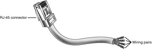
Figure 17.9 A shielded twisted-pair (STP) cable.

Most Ethernet and Fast Ethernet installations that use twisted-pair cabling use UTP because the physical flexibility and small size of the cable and connectors makes routing it very easy. However, its lack of electrical insulation can make interference from fluorescent lighting, elevators, and alarm systems (among other devices) a major problem. If you use UTP in installations where interference can be a problem, you need to route the cable away from the interference, use an external shield, or substitute STP for UTP near interference sources.
Four standard types of unshielded twisted-pair cabling exist and are still used to varying degrees:
• Category 3 cable—The original type of UTP cable used for Ethernet networks was also the same as that used for business telephone wiring. This is known as Category 3, or voice-grade UTP cable, and is measured according to a scale that quantifies the cable’s data-transmission capabilities. The cable itself is 24 AWG (American Wire Gauge, a standard for measuring the diameter of a wire) and copper-tinned with solid conductors, with 100–105 ohm characteristic impedance and a minimum of two twists per foot. Category 3 cable is largely obsolete because it is only adequate for networks running at up to 16Mbps, so it cannot be used with Fast or Gigabit Ethernet.
• Category 5 cable—The faster network types require greater performance levels. Fast Ethernet (100BASE-TX) uses the same two-wire pairs as 10BASE-T, but Fast Ethernet needs a greater resistance to signal crosstalk and attenuation. Therefore, the use of Category 5 UTP cabling is essential with 100BASE-TX Fast Ethernet. Although the 100BASE-T4 version of Fast Ethernet can use all four-wire pairs of Category 3 cable, this flavor of Fast Ethernet is not widely supported and has practically vanished from the marketplace. If you try to run Fast Ethernet 100BASE-TX over Category 3 cable, you will have a slow and unreliable network. Category 5 cable is commonly called CAT 5 and is also referred to as Class D cable.
Many cable vendors also sell an enhanced form of Category 5 cable called Category 5e (specified by Addendum 5 of the ANSI/TIA/EIA-568-A cabling standard). Category 5e cable can be used in place of Category 5 cable and is especially well suited for use in Fast Ethernet networks that might be upgraded to Gigabit Ethernet in the future. Category 5e cabling must pass several tests not required for Category 5 cabling. Even though you can use both Category 5 and Category 5e cabling on a Gigabit Ethernet (1000BASE-TX) network, Category 5e cabling provides better transmission rates and a greater margin of safety for reliable data transmission.
• Category 6 cable—Category 6 cabling (also called CAT 6 or Class E) can be used in place of CAT 5 or 5e cabling and uses the same RJ-45 connectors as CAT 5 and 5e. CAT 6 cable handles a frequency range of 1MHz–250MHz, compared to CAT 5 and 5e’s 1MHz–100MHz frequency range.
• Category 7 cable—Category 7 (also called CAT 7 or Class F) is the newest cabling standard and handles a frequency range of 1MHz–600MHz, which reduces propagation delay and delay skew. This enables longer network cables and larger numbers of workstations on a network. CAT 7 uses the GG45 connector developed by Nexans. This connector resembles the RJ-45 connector but has four additional contacts (see Figure 17.10). The GG45 connector contains a switch that activates a maximum of eight out of 12 contacts. The upper eight RJ-45 contacts are used for up to 250MHz (CAT 6) operation, whereas the eight contacts in the outer edges are used for 600MHz (CAT 7) operation. Only eight contacts are used at a given time. In other words, this connector is designed to be backward compatible with cables using RJ-45 connectors while supporting the newer standard.
Figure 17.10 The GG45 connector from Nexans can accept CAT 5 and other standard network cabling using the RJ-45 connector or the new CAT 7 cabling.

Caution
If you choose to install Category 5/5e UTP cable, be sure that all the connectors, wall plates, and other hardware components involved are also Category 5 rated.
If you are trying to connect prebuilt Category 5 cabling together on a Fast Ethernet network, use Category 5–grade or better connectors; otherwise, you’ll create a substandard section that might fail in your network.
Choosing the correct type of Category 5/5e/6/7 cable is also important. Use solid PVC cable for network cables that represent a permanent installation. However, the slightly more expensive stranded cables are a better choice for laptop computers or temporary wiring of no more than 10-feet lengths (from a computer to a wall socket, for example) because they are more flexible and therefore capable of withstanding frequent movement.
If you plan to use air ducts or suspended ceilings for cable runs, you should use Plenum cable, which doesn’t emit harmful fumes in a fire. It is much more expensive, but the safety issue is a worthwhile reason to use it (some localities require you to use Plenum cabling).
Building Your Own Twisted-Pair Cables
When it’s time to wire your network, you have two choices. You can opt to purchase prebuilt cables, or you can build your own cables from bulk wire and connectors.
You should build your own twisted-pair cables if you
• Plan to perform a lot of networking.
• Need cable lengths longer than the lengths you can buy preassembled at typical computer departments.
• Want to create both standard and crossover cables.
• Want to choose your own cable color.
• Want maximum control over cable length.
• Want to save money.
• Have the time necessary to build cables.
Twisted-Pair Wiring Standards
If you want to create twisted-pair (TP) cables yourself, be sure your cable pairs match the color coding of any existing cable or the color coding of any prebuilt cabling you want to add to your new network. Because there are eight wires in TP cables, many incorrect combinations are possible. Several standards exist for UTP cabling.
Tip
The key is to be consistent. Use the same scheme for all your cables, and ensure that anyone else working on your network understands this scheme.
One common standard is the AT&T 258A configuration (also called EIA/TIA 568B). Table 17.4 lists the wire pairing and placement within the standard RJ-45 connector.
Table 17.4 RJ-45 Connector Wire Pairing and Placement for AT&T 258A/EIA 568B Standard

In Figure 17.11, an RJ-45 cable connector is wired to the AT&T 258A/EIA 568B standard.
Figure 17.11 An AT&T 258A/EIA 568B standard–compliant RJ-45 connector.

Note
You also might encounter the similar EIA 568A standard. It reverses the position of the orange and green pairs listed previously.
Crossover UTP Cables
Crossover cables, which change the wiring at one end of the cable, are used to connect two (and only two) computers when no hub or switch is available or to connect a hub or switch without an uplink port to another hub or switch. The pinout for a crossover cable is shown in Table 17.5. This pinout is for one end of the cable only; the other end of the cable should correspond to the standard EIA 568B pinout, as shown previously in Figure 17.11.
Table 17.5 RJ-45 Connector Wire Pairing and Placement for Crossover Variation on EIA 568B Standard

Note
It should be noted that other wiring schemes exist, such as IEEE and USOC. All told, at least eight agreed-on standards exist for connecting UTP cables and RJ-45 connectors. The ones listed in this chapter are the most common.
Constructing the Cable
Making your own UTP cables requires a few tools that aren’t commonly found in a typical toolbox. Those items that you might not already have you can typically purchase for a single price from many network-products vendors. You will need the following tools and supplies to build your own Ethernet cables:
• UTP cable (Category 5 or better)
• RJ-45 connectors
• Wire stripper
• RJ-45 crimping tool
Before you make a “real” cable of any length, you should practice on a short length of cable. RJ-45 connectors and bulk cable are cheap; network failures are not. Follow these steps for creating your own twisted-pair cables:
1. Determine how long your UTP cable should be. You should allow adequate slack for moving the computer and for avoiding strong interference sources. Keep the maximum distances for UTP cables of about 100 meters in mind.
2. Roll out the appropriate length of cable.
3. Cut the cable cleanly from the box of wire.
4. Use the wire stripper to strip only the insulation jacket off the cable, exposing the TP wires (see Figure 17.12); you’ll need to rotate the wire about one and a quarter turns to strip away all the jacket. If you turn it too far, you’ll damage the wires inside the cable.
Figure 17.12 Carefully strip the cable jacket away to expose the four wire pairs.

5. Check the outer jacket and inner TP wires for nicks; adjust the stripper tool and repeat steps 3 and 4 if you see damage.
6. As shown in Figure 17.13, arrange the wires according to the EIA 568B standard. This arrangement is listed previously, in the section “Twisted-Pair Wiring Standards.”
Figure 17.13 Arrange the wire pairs for insertion into the RJ-45 connector according to your chosen scheme (EIA 568B, for instance).

7. Trim the wire edges so the eight wires are even with one another and are slightly less than 1/2″ past the end of the jacket. If the wires are too long, crosstalk (wire-to-wire interference) can result; if the wires are too short, they can’t make a good connection with the RJ-45 plug.
8. With the clip side of the RJ-45 plug facing away from you, push the cable into place (see Figure 17.14). Verify that the wires are arranged according to the EIA/TIA 568B standard before you crimp the plug onto the wires (refer to Table 17.5 and Figure 17.11 earlier in this chapter). Adjust the connection as necessary.
Figure 17.14 Push the RJ-45 connector into place, ensuring the cable pairs are ordered properly.

9. Use the crimping tool to squeeze the RJ-45 plug onto the cable (see Figure 17.15). The end of the cable should be tight enough to resist being removed by hand.
Figure 17.15 Firmly squeeze the crimping tool to attach the connector to the cable.

10. Repeat steps 4–9 for the other end of the cable. Recut the end of the cable if necessary before stripping it.
11. Label each cable with the following information:
• Wiring standard
• Length
• End with crossover (if any)
• ________ (a blank) for computer ID
The cables should be labeled at both ends to make matching the cable with the correct computer easy and to facilitate troubleshooting at the hub. Check with your cable supplier for suitable labeling stock or tags you can attach to each cable.
Cable Distance Limitations
The people who design computer systems love to find ways to circumvent limitations. Manufacturers of Ethernet products have made possible the building of networks in star, branch, and tree designs that overcome the basic limitations already mentioned (for more information, see the “Wired Network Topologies” section later in this chapter). Strictly speaking, you can have thousands of computers on a complex Ethernet network.
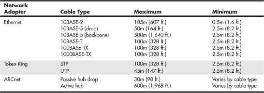
LANs are local because the network adapters and other hardware components typically can’t send LAN messages more than a few hundred feet. Table 17.6 lists the distance limitations of various types of LAN cable. In addition to the limitations shown in the table, keep the following points in mind:
• You can’t connect more than 30 computers on a single Thinnet Ethernet segment.
• You can’t connect more than 100 computers on a Thicknet Ethernet segment.
• You can’t connect more than 72 computers on a UTP Token-Ring cable.
• You can’t connect more than 260 computers on an STP Token-Ring cable.
Table 17.6 Network Distance Limitations
If you have a station wired with Category 5 cable that is more than 328 feet (100 meters) from a hub, you must use a repeater. If you have two or more stations beyond the 328 feet limit of UTP Ethernet, connect them to a hub or switch that is less than 328 feet away from the primary hub or switch and connect the new hub or switch to the primary hub or switch via its uplink port. Because hubs and switches can act as repeaters, this feature enables you to extend the effective length of your network.
Wired Network Topologies
Each computer on the network is connected to the other computers with cable (or some other medium, such as wireless using radio frequency signals). The physical arrangement of the cables connecting computers on a network is called the network topology.
Over the last 15 years the three types of basic topologies used in computer networks have been as follows:
• Bus—Connects each computer on a network directly to the next computer in a linear fashion. The network connection starts at the server and ends at the last computer in the network. (Obsolete.)
• Star—Connects each computer on the network to a central access point.
• Ring—Connects each computer to the others in a loop or ring. (Obsolete.)
For a long while, these different topologies were often mixed, forming what is called a hybrid network. For example, you can link the hubs of several star networks together with a bus, forming a star-bus network. Rings can be connected in the same way.
Table 17.7 summarizes the relationships between network types and topologies.
Table 17.7 Network Cable Types and Topologies

The bus, star, and ring topologies are discussed in the following sections. Wireless networking, which technically doesn’t have a physical topology as described here, does still employ two logical (virtual) topologies, which I discuss as well.
Bus Topology
The earliest type of network topology was the bus topology, which uses a single cable to connect all the computers in the network to each other, as shown in Figure 17.16. This network topology was adopted initially because running a single cable past all the computers in the network is easier and less wiring is used than with other topologies. Because early bus topology networks used bulky coaxial cables, these factors were important advantages. Both 10BASE-5 (thick) and 10BASE-2 (thin) Ethernet networks are based on the bus topology.
Figure 17.16 A 10BASE-2 network is an example of a linear bus topology, attaching all network devices to a common cable.

However, the advent of cheaper and more compact unshielded twisted-pair cabling, which also supports faster networks, has made the disadvantages of a bus topology apparent. If one computer or cable connection malfunctions, it can cause all the stations beyond it on the bus to lose their network connections. Thick Ethernet (10BASE-5) networks often fail because the vampire tap connecting the AUI device to the coaxial cable comes loose. In addition, the T-adapters and terminating resistors on a 10BASE-2 Thin Ethernet network can also come loose or be removed by the user, causing all or part of the network to fail. Another drawback of Thin Ethernet (10BASE-2) networks is that adding a new computer to the network between existing computers might require replacement of the existing network cable between the computers with shorter segments to connect to the new computer’s network card and T-adapter, thus creating downtime for users on that segment of the network.
Note
Although 10BASE-2 Thin Ethernet networks are no longer common in PC installations, you might encounter them in industrial control environments. Because 10BASE-2 combines a positive-locking bayonet connector with a shielded coaxial cable, it’s a better choice for rough environments than UTP or Thick Ethernet networks.
Ring Topology
Another topology often listed in discussions of this type is a ring, in which each workstation is connected to the next and the last workstation is connected to the first again (essentially a bus topology with the two ends connected). Two major network types use the ring topology:
• Fiber Distributed Data Interface (FDDI)—A network topology used for large, high-speed networks using fiber-optic cables in a physical ring topology
• Token-Ring—Uses a logical ring topology
A Token-Ring network resembles a 10BASE-T or 10/100 Ethernet network at first glance because both networks use a central connecting device and a physical star topology. Where is the “ring” in Token-Ring?
The ring exists only within the device that connects the computers, which is called a multistation access unit (MSAU) on a Token-Ring network (see Figure 17.17).
Figure 17.17 A Token-Ring network during the sending of data from one computer to another.
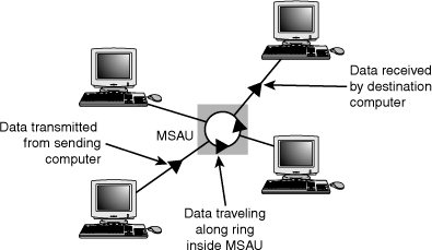
Signals generated from one computer travel to the MSAU, are sent out to the next computer, and then go back to the MSAU again. The data is then passed to each system in turn until it arrives back at the computer that originated it, where it is removed from the network. Therefore, although the physical wiring topology is a star, the data path is theoretically a ring. This is called a logical ring.
A logical ring that Token-Ring networks use is preferable to a physical ring network topology because it affords a greater degree of fault tolerance. As on a bus network, a cable break anywhere in a physical ring network topology, such as FDDI, affects the entire network. FDDI networks use two physical rings to provide a backup in case one ring fails. By contrast, on a Token-Ring network, the MSAU can effectively remove a malfunctioning computer from the logical ring, enabling the rest of the network to function normally.
Star Topology
By far the most popular type of topology in use today has separate cables to connect each computer to a central wiring nexus, often called a switch or hub. Figure 17.18 shows this arrangement, which is called a star topology.
Figure 17.18 The star topology, linking the LAN’s computers and devices to one or more central hubs, or access units.
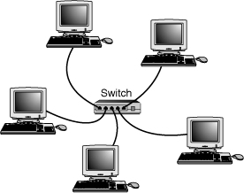
Because each computer uses a separate cable, the failure of a network connection affects only the single machine involved. The other computers can continue to function normally. Bus cabling schemes use less cable than the star but are harder to diagnose or bypass when problems occur. At this time, Fast Ethernet and Gigabit Ethernet in a star topology are the most commonly implemented types of wired LAN. 10BASE-T Ethernet and 1000BASE-TX Gigabit Ethernet also use the star topology.
Switches and Hubs for Ethernet Networks
As you have seen, modern Ethernet workgroup networks—whether wireless or wired with UTP cable—are usually arranged in a star topology. The center of the star uses a multiport connecting device that can be either a hub or a switch. Although hubs and switches can be used to connect the network—and can have several features in common—the differences between them are also significant and are covered in the following sections.
All Ethernet hubs and switches have the following features:
• Multiple RJ-45 UTP connectors (wireless switches still include wired ports)
• Diagnostic and activity lights
• A power supply
Ethernet hubs and switches are made in two forms: managed and unmanaged. Managed hubs and switches can be directly configured, enabled or disabled, or monitored by a network operator. They are commonly used on corporate networks. Workgroup and home-office networks use less expensive unmanaged hubs, which simply connect computers on the network using the systems connected to it to provide a management interface for its configurable features.
Signal lights on the front of the hub or switch indicate which connections are in use by computers; switches also indicate whether a full-duplex connection is in use. Multispeed hubs and switches also indicate which connection speed is in use on each port. Your hub or switch must have at least one RJ-45 UTP connector for each computer you want to connect to it.
How Hubs Work
A computer on an Ethernet network broadcasts (sends) a request for network information or programs from a specific computer through the cable to the hub, which broadcasts the request to all computers connected to it. When the destination computer receives the message, it sends the requested information back to the hub, which broadcasts it again to all computers, although only the requesting computer acts on the information. Thus, a hub acts similarly to a radio transmitter and receiver that sends a signal to all radios, but only the radios set for the correct station can send or receive the information. Switches, due to the features explained in the next section, have replaced hubs on retail store shelves.
How Switches Differ from Hubs
Switches, as shown in Figure 17.19, are similar to hubs in both form factor and function. As with hubs, they connect computers on an Ethernet network to each other. However, instead of broadcasting data to all computers on the network as hubs do, switches use a feature called address storing, which checks the destination for each data packet and sends it directly to the computer for which it’s intended. Thus, a switch can be compared to a telephone exchange, making direct connections between the originator of a call and the receiver.
Figure 17.19 Front (top) and rear (bottom) of a typical five-port, 10/100 Ethernet switch.

Because switches establish a direct connection between the originating and receiving PC, they also provide the full bandwidth of the network to each port. Hubs, by contrast, must subdivide the network’s bandwidth by the number of active connections on the network, meaning that bandwidth rises and falls depending on network activity.
For example, assume you have a four-station network workgroup using 10/100 NICs and a Fast Ethernet hub. The total bandwidth of the network is 100Mbps. However, if two stations are active, the effective bandwidth available to each station drops to 50Mbps (100Mbps divided by 2). If all four stations are active, the effective bandwidth drops to just 25Mbps (100Mbps divided by 4)! Add more active users, and the effective bandwidth continues to drop.
If you replace the hub with a switch, the effective bandwidth for each station remains 100Mbps because the switch doesn’t broadcast data to all stations.
Most 10/100 NICs and Fast Ethernet or 10/100 switches also support full-duplex (simultaneous transmit and receive), enabling the actual bandwidth to be double the nominal 100Mbps rating: 200Mbps. Table 17.8 summarizes the differences between the two devices.
Table 17.8 Ethernet Hub and Switch Comparison
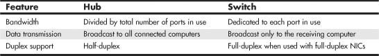
As you can see, using a switch instead of a hub greatly increases the effective speed of a network, even if all other components remain the same.
Note
Both wired and wireless routers (a router connects a local area network to a device that provides Internet access, such as a cable or DSL modem) typically incorporate full-duplex 10/100 (Fast Ethernet) or 10/100/1000 (Gigabit Ethernet) switches. Therefore, a router can be used in place of a switch.
![]() For more information about routers, see “Routers for Internet Sharing,” p. 861 (Chapter 16, “Internet Connectivity”).
For more information about routers, see “Routers for Internet Sharing,” p. 861 (Chapter 16, “Internet Connectivity”).
If you are satisfied with the performance of your network using hubs, you do not need to replace them with switches. However, keep in mind that newer network uses such as VoIP, multimedia content viewing, and others require much more performance than a hub can provide.
Additional Switch Features You Might Need
Although older hubs and switches run at only a single speed and have only a few RJ-45 connectors, it makes sense to upgrade to newer, more flexible equipment. Most recent switches have the following useful features, which are worth asking for:
• Multispeed switches—If you are adding Gigabit Ethernet (1000BASE-TX) or Fast Ethernet (100BASE-TX) clients to an existing 10BASE-T network, you need a multispeed switch to connect the various types of Ethernet together.
Even if you are building a brand-new Gigabit Ethernet or Fast Ethernet network, a multispeed switch is useful for occasionally hosting a “guest” PC that has only a slower-speed NIC onboard. Even though most Gigabit Ethernet and Fast Ethernet switches on the market today are actually 10/100/1000 or 10/100 multispeed models, you might still encounter a single-speed-only unit. These single-speed units should be used only on networks that will never have a need to support a slower connection.
• Wireless access point—Many switches today also feature a built-in wireless access point or router that supports 802.11b/g, 802.11a, or 802.11n (some access points supports 802.11b/g/n or 802.11b/a/g/n). If you plan to implement a wireless network in the future, getting a switch with a wireless access point built in now is worth the minimal increase in cost.
• Stackable switch with an uplink port—A stackable hub or switch is one that can be connected to another hub or switch (and often stacked on top of it), enabling you to add computers to your network without replacing the hub or switch every time it runs out of connections. Most switches on the market today are stackable, but some older models might lack this feature. You can use this feature to add 10/100/1000 features to an older 10BASE-T-only network and connect a multispeed switch to the uplink port on your 10BASE-T switch. The uplink port includes a built-in crossover, so you can use a standard cable.
Tip
To determine whether a switch (or hub) is stackable, look for an uplink port. This port looks like an ordinary RJ-45 UTP port, but it is wired differently, enabling you to use a standard-pinout RJ-45 UTP cable to connect it to another switch. Without the uplink port, you’d have to use a specially wired crossover cable.
• “Extra” ports beyond your current requirements—If you are connecting four computers together into a small network, you need a four-port switch (the smallest available). But, if you buy a switch with only four ports and want to add another client PC to the network, you must add a second switch or replace the switch with a larger one with more ports.
Instead, plan for the future by buying a switch that can handle your projected network growth over the next year. If you plan to add two workstations, buy at least an eight-port switch (the cost per connection drops as you buy hubs and switches with more connections). Even though most hubs and switches are stackable to support the growth of your network, the more ports a hub or switch has, the less expensive per port it will be.
Note
The uplink port on your switch (or hub) is also used to connect the device to a router or gateway device that provides an Internet connection for your network. In cases where multiple switches are to be used, they are usually connected directly to the router or gateway instead of chained (or stacked) off each other.
Typically, switches (or hubs) with an uplink port allow you to use the port along with all but one of the normal ports on the switch (or hub). See Figure 17.19 for an example of a switch with an uplink port.
For example, one of my associates uses a five-port switch from Linksys that also contains a router (for Internet access) and an uplink port. If his office network expands beyond five computers, he can use the uplink port to add another switch to expand the network and provide the new stations, as well as the original network, with Internet access.
Switch Placement
Although large networks have a wiring closet near the server, the workgroup-size LANs found in a small office/home office (SOHO) network obviously don’t require anything of the sort. However, the location of the switch is important, even if your LAN is currently based solely on a wireless Ethernet architecture.
Ethernet switches (and hubs) require electrical power, whether they are small units that use a power “brick” or larger units that have an internal power supply and a standard three-prong AC cord.
In addition to electrical power, consider placing the hub or switch where its signal lights will be easy to view for diagnostic purposes and where its RJ-45 connectors can be reached easily. This is important both when it’s time to add another user or two and when you need to perform initial setup of the switch (requiring a wired connection) or need to troubleshoot a failed wireless connection. In many offices, the hub or switch sits on the corner of the desk, enabling the user to see network problems just by looking at the hub or switch.
If the hub or switch also integrates a router for use with a broadband Internet device, such as a DSL or cable modem, you can place it near the cable or DSL modem or at a distance if the layout of your home or office requires it. Because the cable or DSL modem usually connects to your computer by the same Category 5/5e/6/7 cable used for UTP Ethernet networking, you can run the cable from the cable or DSL modem to the router/switch’s WAN port and connect all the computers to the LAN ports on the router/switch.
Except for the 328-ft. (100-meter) limit for all forms of UTP Ethernet (10BASE-T, 100BASE-TX, and 1000BASE-TX), distances between each computer on the network and the switch (or hub) aren’t critical, so put the switch (or hub) wherever you can supply power and gain easy access.
Although wireless networks do offer more freedom in terms of placing the switch/access point, you should keep in mind the distances involved (generally up to 150 feet indoors for 802.11b/g) and any walls or devices using the same 2.4GHz spectrum that might interfere with the signal.
Tip
Decide where you plan to put your hub or switch before you buy prebuilt UTP wiring or make your own; if you move the hub or switch, some of your wiring will no longer be the correct length. Although excess lengths of UTP cable can be coiled and secured with cable ties, cables that are too short should be replaced. You can buy RJ-45 connectors to create one long cable from two short cables, but you must ensure the connectors are Category 5 if you are running Fast Ethernet; some vendors still sell Category 3 connectors that support only 10Mbps. You’re really better off replacing the too-short cable with one of the correct length.
Wireless Ethernet Hardware
All types of 802.11 wireless networks have two basic components:
• Access points
• NICs equipped with radio transceivers
An access point is a bookend-size device that uses one or more RJ-45 ports to attach to a 10BASE-T or 10/100 Ethernet network (if desired) and contains a radio transceiver, encryption, and communications software. It translates conventional Ethernet signals into wireless Ethernet signals that it broadcasts to wireless NICs on the network and then performs the same role in reverse to transfer signals from wireless NICs to the conventional Ethernet network.
Note
In SOHO networks that provide Internet access, the access point is usually incorporated into a wireless router that also includes an Ethernet switch.
For coverage of a large area, purchase two or more access points and connect them to an Ethernet switch. This enables users to roam inside a building without losing contact with the network. Some access points can communicate directly with each other via radio waves, enabling you to create a wireless backbone that can cover a wide area (such as a warehouse) without the need to run any network cabling. You can also purchase a wireless Ethernet range extender that can receive and boost weak Wi-Fi signals. Some access points are designed to be used as either access points or range extenders. Some range extenders are designed only to work with the same brand of access point or router.
Access points are not necessary for direct peer-to-peer networking (also called ad hoc mode), but they are required for a shared Internet connection or a connection with another network. When access points are used, the network is operating in infrastructure mode.
Note
Wireless clients running in ad hoc mode cannot connect to the Internet unless one of the stations on the network is connected to a bridge or uses another network adapter as a bridge.
NICs equipped for wireless Ethernet communications have a fixed or detachable radio antenna. Wireless NICs come in four forms:
• CardBus (32-bit PC Card) cards for use in laptop computers that do not include “integrated” wireless support
• Mini PCI or PCIe Mini cards that provide wireless and wired Ethernet and dial-up modem support for laptop computers
• PCI cards for use in desktop computers with PCI slots
• USB adapters for use in both desktop and laptop computers
Most laptop computers with Wi-Fi hardware onboard use the Mini PCI interface for the wireless adapter and place the antenna inside the screen housing. This enables computers with built-in Wi-Fi hardware to have one more open PC Card slot than computers that must use an external PC Card adapter and antenna.
Note
Mini PCI or PCIe Mini cards are installed inside laptop computers. (They can be removed or replaced by opening up the system.) Because Mini PCI and PCIe Mini cards are installed inside laptops, they are not usually sold as retail components. However, they are sold by some vendors as OEM components, or you can buy them from the laptop vendor’s parts department.
Because you can mix and match Wi-Fi-certified products that use the same frequency band, you can incorporate any mix of desktop and laptop computers into your wireless network. Figure 17.20 illustrates typical wireless network hardware.
Figure 17.20 A typical family of Wi-Fi 2.4GHz band (802.11g) wireless products, including a wireless router, USB, CardBus, and PCI wireless network adapters. (Photos courtesy of Cisco.)

Although most recent laptop computers include 802.11g wireless Ethernet or dual-mode 802.11g/a support through an integrated Mini PCI card, you can add support for other 802.11 wireless networks through the CardBus slot or USB 2.0 port.
In cases where a Wi-Fi-enabled system receives multiple Wi-Fi signals, client systems lock onto the strongest signal from access points and automatically roam (switch) to another access point when the signal strength is stronger and the error level is lower than the current connection. Of course, if you want the system to lock onto a specific signal, that can be done via the OS or manufacturer-provided software.
Additional hardware you might need to add to your network includes the following:
• Wireless bridges—These devices enable you to connect a wired Ethernet device, including noncomputer items such as video games or set-top boxes, to a wireless network.
• Wireless repeaters/range extenders—A repeater can be used to stretch the range of an existing wireless network. Some can also be used as access points or wireless bridges.
• Wireless router—Use this in place of a standard access point to enable a wireless network to connect to the Internet through a cable modem or other broadband device (refer to Chapter 16 for details). For additional flexibility, many wireless routers also include a multiport switch for use with wired Ethernet networks, and some also include a print server.
• Specialized antennas—The “rabbit ears” antennas used by most access points and routers are adequate for short distances, but longer distances or problems with line-of-sight reception can be solved by attaching a specialized ceiling, wall, omnidirectional, or directional antenna in place of the standard antenna.
• Signal boosters—In addition to or as an alternative to replacement antennas, some vendors also sell signal boosters that piggyback onto an existing access point or router. Note that, in most cases, these signal boosters are vendor specific.
Wireless Network Logical Topologies
Wireless networks have different topologies, just as wired networks do. However, wireless networks use only two logical topologies:
• Star—The star topology, used by Wi-Fi/IEEE 802.11–based products in the infrastructure mode, resembles the topology used by 10BASE-T and faster versions of Ethernet that use a switch (or hub). The access point takes the place of the switch because stations connect via the access point, rather than directly with each other. This method is much more expensive per unit but permits performance in excess of 10BASE-T Ethernet speeds and has the added bonus of being easier to manage.
• Point-to-point—Bluetooth products (as well as Wi-Fi products in the ad hoc mode) use the point-to-point topology. These devices connect directly with each other and require no access point or other hub-like device to communicate with each other, although shared Internet access does require that all computers connect to a common wireless gateway. The point-to-point topology is much less expensive per unit than a star topology. It is, however, best suited for temporary data sharing with another device (Bluetooth) and is currently much slower than 100BASE-TX networks.
Figure 17.21 shows a comparison of wireless networks using these two topologies.
Figure 17.21 A logical star topology (left) as used by IEEE 802.11–based wireless Ethernet in infrastructure mode compared to a point-to-point topology as used by Bluetooth and 802.11 in ad hoc mode (right).

Wireless Network Security
When I was writing the original edition of Upgrading and Repairing PCs back in the 1980s, the hackers’ favorite way of trying to get into a network without authorization was discovering the telephone number of a modem on the network, dialing in with a computer, and guessing the password, as in the movie War Games. Today, war driving has largely replaced this pastime as a popular hacker sport. War driving is the popular name for driving around neighborhoods with a laptop computer equipped with a wireless network card on the lookout for unsecured networks. They’re all too easy to find, and after someone gets onto your network, all the secrets in your computer can be theirs for the taking.
Because wireless networks can be accessed by anyone within signal range who has a NIC matching the same IEEE standard of that wireless network, wireless NICs and access points provide for encryption options. Most access points (even cheaper SOHO models) also provide the capability to limit connections to the access point by using a list of authorized MAC numbers (each NIC has a unique MAC). It’s designed to limit access to authorized devices only.
Although MAC address filtering can be helpful in stopping bandwidth borrowing by your neighbors, it cannot stop attacks because the MAC address can easily be “spoofed” or faked. Consequently, you also need to look at other security features included in wireless networks, such as encryption.
Caution
In the past, it was thought that the SSID feature provided by the IEEE 802.11 standards was also a security feature. That’s not the case. A Wi-Fi network’s SSID is nothing more than a network name for the wireless network, much the same as workgroups and domains have network names that identify them. The broadcasting of the SSID can be turned off (when clients look for networks, they won’t immediately see the SSID), which has been thought to provide a minor security benefit. However, Microsoft has determined that a non-broadcast SSID is actually a greater security risk than a broadcast SSID, especially with Windows XP and Windows Server 2003. For details, see “Non-broadcast Wireless Networks with Microsoft Windows” at http://technet.microsoft.com/en-us/library/bb726942.aspx. In fact, many freely available (and quite powerful) tools exist that allow snooping individuals to quickly discover your SSID even if it’s not being broadcast, thus allowing them to connect to your unsecured wireless network.
The only way that the SSID can provide a small measure of security for your wireless network is if you change the default SSID provided by the wireless access point or router vendor. The default SSID typically identifies the manufacturer of the device (and sometimes even its model number). A hacker armed with this information can look up the default password and username for the router or access point as well as the default network address range by downloading the documentation from the vendor’s website. Using this information, the hacker could compromise your network if you do not use other security measures, such as WPA/WPA2 encryption. By using a nonstandard SSID and changing the password used by your router’s web-based configuration program, you make it a little more difficult for hackers to attack your network. Follow up these changes by enabling the strongest form of encryption supported by your wireless network.
All Wi-Fi products support at least 40-bit encryption through the wired equivalent privacy (WEP) specification, but the minimum standard on recent products is 64-bit WEP encryption. Many vendors offer 128-bit or 256-bit encryption on some of their products. However, the 128-bit and stronger encryption feature is more common among enterprise products than SOHO–oriented products. Unfortunately, the WEP specification at any encryption strength has been shown to be notoriously insecure against determined hacking. Enabling WEP will keep a casual snooper at bay, but someone who wants to get into your wireless network won’t have much trouble breaking WEP. For that reason, all wireless network products introduced after 2003 incorporate a different security standard known as Wi-Fi Protected Access (WPA). WPA is derived from the developing IEEE 802.11i security standard. WPA-enabled hardware works with existing WEP-compliant devices, and software upgrades are often available for existing devices to make them WPA capable. The latest 802.11g and 802.11n devices also support WPA2, an updated version of WPA that uses a stronger encryption method (WPA uses TKIP; WPA2 uses AES).
Note
Unfortunately, most 802.11b wireless network hardware supports only WEP encryption. The lack of support for more powerful encryption standards is a good reason to retire your 802.11b hardware in favor of 802.11g or 802.11n Draft 2 hardware, all of which support WPA or WPA2 encryption.
Upgrading to WPA or WPA2 may also require updates to your operating system. For example, Windows XP Service Pack 2 includes support for WPA encryption. However, to use WPA2 with Windows XP Service Pack 2, you must also download the Wireless Client Update for Windows XP with Service Pack 2, or install Service Pack 3. At the http://support.microsoft.com website, look up Knowledge Base article 917021. You should match the encryption level and encryption type used on both the access points and the NICs for best security. Remember that if some of your network supports WPA but other parts support only WEP, your network must use the lesser of the two security standards (WEP). If you want to use the more robust WPA or WPA2 security, you must ensure that all the devices on your wireless network support WPA. Because WEP is easily broken and the specific WEP implementations vary among manufacturers, I recommend using only devices that support WPA or WPA2.
Management and DHCP Support
Most wireless access points can be managed via a web browser and provide diagnostic and monitoring tools to help you optimize the positioning of access points. Most products feature support for Dynamic Host Configuration Protocol (DHCP), allowing a user to move from one subnet to another without difficulties.
Figure 17.22 illustrates how a typical IEEE 802.11 wireless network uses multiple access points.
Figure 17.22 A typical wireless network with multiple access points. As users with wireless NICs move from one office to another, the roaming feature of the NIC automatically switches from one access point to another, permitting seamless network connectivity without wires or logging off the network and reconnecting.
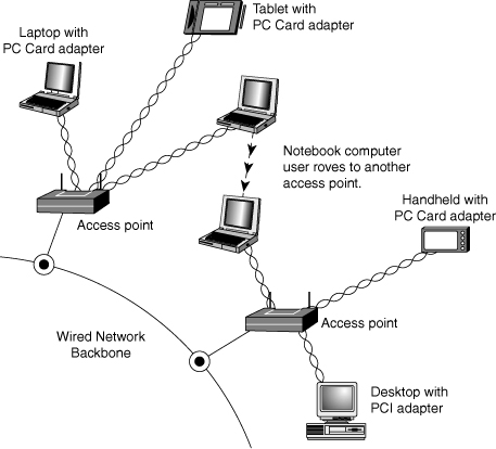
Users per Access Point
The number of users per access point varies with the product; Wi-Fi access points are available in capacities supporting anywhere from 15 to as many as 254 users. You should contact the vendor of your preferred Wi-Fi access point device for details.
Although wired Ethernet networks are still the least expensive networks to build if you can do your own wiring, Wi-Fi networking is now cost-competitive with wired Ethernet networks when the cost of a professional wiring job is figured into the overall expense.
Because Wi-Fi is a true standard, you can mix and match access point and wireless NIC hardware to meet your desired price, performance, and feature requirements for your wireless network, just as you can for conventional Ethernet networks, provided you match up frequency bands or use dual-band hardware.
Network Protocols
A few years ago, the second-most important choice you had to make when you created a network was which network protocol to use because the network protocol affects which types of computers your network can connect. Today, the choice has largely been made for you: TCP/IP has replaced other network protocols such as IPX/SPX (used in older versions of Novell NetWare) and NetBEUI (used in older Windows and DOS-based peer-to-peer networks and with Direct Cable Connection) because it can be used both for Internet and LAN connectivity. TCP/IP is also a universal protocol that can be used by virtually all operating systems.
Although data-link protocols such as Ethernet require specific types of hardware, network protocols are software and can be installed to or removed from any computer on the network at any time, as necessary. Table 17.9 summarizes the differences between these protocols.
Table 17.9 Overview of Network Protocols and Suites

All the computers on any given network must use the same network protocol or protocol suite to communicate with each other.
IP and TCP/IP
IP stands for Internet Protocol; it is the network layer of the collection of protocols (or protocol suite) developed for use on the Internet and commonly known as TCP/IP (Transmission Control Protocol/Internet Protocol).
Later, the TCP/IP protocols were adopted by the Unix operating systems, and they have now become the most commonly used protocol suite on PC LANs. Virtually every operating system with networking capabilities supports TCP/IP, and it is well on its way to displacing all the other competing protocols. Novell NetWare 6 and above, Linux, Windows XP, and Windows Vista use TCP/IP as their native network protocol.
TCP/IP—LAN and Dialup Networks
TCP/IP, unlike the other network protocols listed in the previous section, is also a protocol used by people who have never seen a NIC. People who access the Internet via modems (this is referred to as Dial-Up Networking in some older Windows versions) use TCP/IP just as those whose web access is done with their existing LANs. Although the same protocol is used in both cases, the settings vary a great deal.
Table 17.10 summarizes the differences you’re likely to encounter. If you access the Internet with both modems and a LAN, you must ensure that the TCP/IP properties for modems and LANs are set correctly. You also might need to adjust your browser settings to indicate which connection type you are using. Table 17.10 provides general guidelines; your ISP or network administrator can give you the specific details.
Table 17.10 TCP/IP Properties by Connection Type—Overview

As you can see from Table 17.10, correct settings for LAN access to the Internet and dialup networking (modem) settings are almost always completely different. In general, the best way to get your dialup networking connection working correctly is to use your ISP’s automatic setup software. This is usually supplied as part of your ISP’s signup software kit. After the setup is working, view the properties and record them for future troubleshooting use.
IPX
The IPX protocol suite (often referred to as IPX/SPX) is the collective term for the proprietary protocols Novell created for its NetWare operating system. Although based loosely on some of the TCP/IP protocols, Novell privately holds the IPX protocol standards. However, this has not prevented Microsoft from creating its own IPX-compatible protocol for the Windows operating systems.
IPX (Internetwork Packet Exchange) itself is a network layer protocol that is equivalent in function to IP. The suite’s equivalent to TCP is the Sequenced Packet Exchange (SPX) protocol, which provides connection-oriented, reliable service at the transport layer.
The IPX protocols typically are used today only on networks with NetWare servers running older versions of NetWare and often are installed along with another protocol suite, such as TCP/IP. Novell has phased out its use of IPX for NetWare support and switched to TCP/IP—along with the rest of the networking industry—starting with NetWare 5. NetWare 5 uses IPX/SPX only for specialized operations. Most of the product uses TCP/IP. NetWare version 6 and above use TCP/IP exclusively.
NetBEUI
NetBIOS Extended User Interface (NetBEUI) is a protocol that was used primarily on small Windows NT networks, as well as on peer networks based on Windows for Workgroups and Windows 9x. It was the default protocol in Windows NT 3.1, the first version of that operating system. Later versions, however, use the TCP/IP protocols as their default.
NetBEUI is a simple protocol that lacks many of the features that enable protocol suites such as TCP/IP to support networks of almost any size. NetBEUI is not routable, so it can’t be used on large internetworks. It is suitable for small peer-to-peer networks, but the last Windows versions to include it as a normal component were Windows Me and Windows 2000. Windows XP does not install NetBEUI as part of its standard network components, but it can be installed from the Windows XP CD. Neither Windows Vista nor Windows 7 support (or include) NetBEUI.
Note
For more information on installing and using NetBEUI in Windows XP, see the Microsoft Knowledge Base article “How to install NetBEUI on Windows XP” (article number 301041) available at http://support.microsoft.com.
NetBEUI is still useful for creating “instant networks” with the Direct Cable Connection, and it is the minimum protocol required for use in a Windows 9x peer-to-peer network.
Other Home Networking Solutions
If you are working at home or in a small office, you have an alternative to hole-drilling, pulling specialized network cabling, or setting up a wireless network.
So-called “home” networking is designed to minimize the complexities of cabling and wireless configuration by providing users with a sort of instant network that requires no additional wiring and configures with little technical understanding.
The two major standards in this area are
• HomePNA (uses existing telephone wiring)
• HomePlug (uses existing powerlines and outlets)
HomePNA
Other than using Ethernet (wired or wireless), the most popular form of home networking involves adapting existing telephone wiring to networking by running network signals at frequencies above those used by the telephone system. Because HomePNA is the most developed and most broadly supported type of home networking, this discussion focuses on the HomePNA standards the Home Phoneline Networking Alliance (www.homepna.org) has created. This alliance has most of the major computer hardware and telecommunications vendors among its founding and active membership.
The Home Phoneline Networking Alliance has developed three versions of its HomePNA standard. HomePNA 1.0, introduced in 1998, ran at only 1Mbps and was quickly superseded by HomePNA 2.0 in late 1999. HomePNA 2.0 supported up to 32Mbps, although most products ran at 10Mbps, bringing it to parity with 10BASE-T Ethernet. Although some vendors produced HomePNA 1.0 and 2.0 products, these versions of HomePNA never became very popular. Both of these products use a bus topology that runs over existing telephone wiring and are designed for PC networking only.
With the development of HomePNA 3.1, the emphasis of HomePNA has shifted from strictly PC networking to a true “digital home” solution that incorporates PCs, set-top boxes, TVs, and other multimedia hardware on a single network.
HomePNA 3.1 and the Digital Home
HomePNA 3.1 is the latest version of the HomePNA standard. In addition to telephone wiring, HomePNA 3.1 also supports coaxial cable used for services such as TV, set-top boxes, and IP phones. HomePNA 3.1 incorporates both types of wiring into a single network (see Figure 17.23) that runs at speeds up to 320Mbps, carries voice, data, and IPTV service, and provides guaranteed quality of service (QoS) to avoid data collisions and avoid disruptions to VoIP and streaming media. HomePNA refers to the ability to carry VoIP, IPTV, and data as a “triple-play.” HomePNA 3.1 also supports remote management of the network by the service provider.
Figure 17.23 A typical HomePNA 3.1 network interconnecting PC, telephone, and TV service via telephone and coaxial cables.
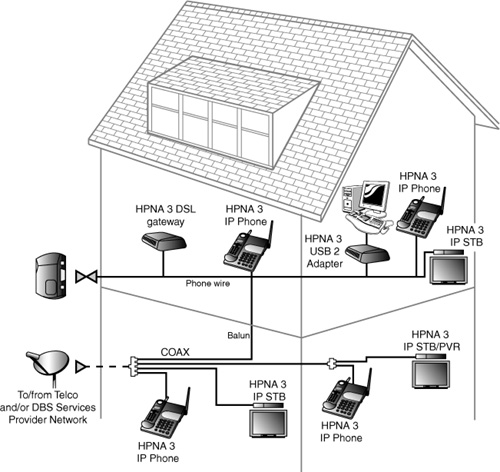
Because HomePNA 3.1 has been designed to handle a mixture of traditional data and Internet telephone (VoIP) and TV (IPTV) service, HomePNA 3.1 hardware is being installed and distributed by telephone and media providers, rather than being sold primarily through retail channels. For example, AT&T uses HomePNA 3.1 for its AT&T U-verse IPTV, broadband, and VoIP service.
Note
For more information about AT&T U-verse, see the AT&T U-verse website at https://uverse1.att.com/launchAMSS.do. AT&T U-verse users and others share information at the UverseUsers website (www.uverseusers.com).
![]() For more information about sharing Internet access and broadband Internet devices, see Chapter 16.
For more information about sharing Internet access and broadband Internet devices, see Chapter 16.
Powerline Networking
Home networking via power lines has been under development for several years, but electrical interference, inconsistent voltage, and security issues made the creation of a workable standard difficult until mid-2001. In June 2001, the HomePlug Powerline Alliance, a multivendor industry trade group, introduced its HomePlug 1.0 specification for 14Mbps home networking using power lines. The HomePlug Powerline Alliance (www.homeplug.org) conducted field tests in about 500 households early in 2001 to develop the HomePlug 1.0 specification.
HomePlug 1.0 is based on the PowerPacket technology developed by Intellon. PowerPacket uses a signaling method called orthogonal frequency division multiplexing (OFDM), which combines multiple signals at different frequencies to form a single signal for transmission. Because OFDM uses multiple frequencies, it can adjust to the constantly changing characteristics of AC power. To provide security, PowerPacket also supports 56-bit DES encryption and an individual key for each home network. By using PowerPacket technology, HomePlug 1.0 is designed to solve the power quality and security issues of concern to a home or small-office network user. Although HomePlug 1.0 is rated at 14Mbps, typical real-world performance is usually around 4Mbps for LAN applications and around 2Mbps when connected to a broadband Internet device such as a cable modem.
HomePlug 1.0 products include USB and Ethernet adapters, bridges, and routers, enabling most recent PCs with USB or Ethernet ports to use Powerline networking for LAN and Internet sharing. Linksys was the first to introduce HomePlug 1.0 products in late 2001; other leading vendors producing HomePlug hardware include Phonex, NetGear, and Asoka. HomePlug Turbo, an updated version of the HomePlug 1.0 standard, supports data rates up to 85Mbps, with typical throughput in the 15Mbps–20Mbps range.
An improved HomePlug AV specification with support for faster speeds (up to 200Mbps), multimedia hardware, and guaranteed bandwidth for multimedia applications was announced in the fall of 2002; the final HomePlug AV specification was approved in August 2005.
The HomePlug Powerline Alliance is also developing standards for broadband over power line (BPL) and for command and control of household lighting and appliances (CC). As a consequence, a new certification mark has been developed to indicate which HomePlug certifications are supported by a particular device. Figure 17.24 shows the original and new HomePlug certification marks.
Figure 17.24 The HomePlug Powerline Alliance certification marks. The original mark (left) for HomePlug 14Mbps network devices only is being replaced by the new multipurpose mark (right).

Putting Your Network Together
In this section is a detailed checklist of the hardware and software you need to build your network.
First, start with the number of computers you plan to network together. You need the items discussed in this section to set up your network.
Network Adapters
Every system needs a network adapter or interface card. These are normally built in, but can also be added in the form of a card.
Traditionally, network adapters are also called network interface cards (NICs). To simplify technical support and minimize the number of different drivers you have to deal with, I recommend you use the same make and model of NIC for each computer in your network (if possible).
For the best performance in a wired network, I recommend using only Gigabit Ethernet components, especially with regards to NICs and switches. If your system has a built-in Fast Ethernet (100Mbps) NIC, you might consider replacing it with a Gigabit Ethernet card. I recommend PCI-Express-based Gigabit NICs for desktop computers and ExpressCard Gigabit NICs for laptop computers with ExpressCard slots. (ExpressCard includes the PCI-Express bus.) If these slots are not available, use PCI or CardBus cards instead.
USB network adapters can be convenient, but USB 1.1 sockets are much slower than 10/100 Ethernet and will slow any USB-attached network interface. USB 2.0 devices are satisfactory for connecting 10/100 Ethernet USB adapters, but are totally inadequate for Gigabit Ethernet adapters. If you truly want Gigabit Ethernet performance, avoid USB and use a PCI, PCIe, or ExpressCard-based card instead.
You should record the brand name and model number of the network adapters you are using, as well as the driver version or source. Use Table 17.11 in the “Recording Information About Your Network” section, later in this chapter, as a template for storing this information.
Table 17.11 Network Hardware Worksheet

Installing the Network Adapter
When installing an internal network card, follow this procedure:
1. Open the case and locate an open expansion slot that matches the type of NIC you purchased (preferably PCI or PCI-Express).
2. Using a screwdriver, remove the screw securing the slot cover at the rear of the case.
3. Insert the card gently, ensuring that the edge connector is seated solidly in the slot.
4. Fasten down the card with the same screw that held the slot cover.
![]() See Figures 19.26 and 19.27 in Chapter 19, “Building or Upgrading Systems,” p. 997, for an example of installing an add-on card.
See Figures 19.26 and 19.27 in Chapter 19, “Building or Upgrading Systems,” p. 997, for an example of installing an add-on card.
Tip
If you are a realist like me, you might not want to close the case until you are certain the NIC is working (see the next section, “Testing Your Network Adapters and Connections”).
Once the network adapter is installed, you need to install the drivers for the card that match your OS.
Testing Your Network Adapters and Connections
Connect the network adapter to the network. With an Ethernet network using UTP cable, run the cable from the card to the switch, turn on the computer and switch, and watch for signal lights to light up on the NIC’s back bracket (if so equipped) and on the switch. Switches normally use LEDs to indicate the presence of a computer on a particular port, and they usually indicate the connected speed. If the LEDs show that the card is connected at the correct speed, that usually indicates the card and intervening cabling are functioning correctly. For other types of networks, see the diagnostics provided with the network hardware for testing details.
Cables and Connections Between Computers
Depending on the network architecture you choose, you might need to run cables. If you are installing a Fast or Gigabit Ethernet network (both of which use UTP cables), you need cables that are long enough to reach comfortably between each computer’s network port and the network’s hub or switch. Use Table 17.11 in the “Recording Information About Your Network” section, later in this chapter, as a template for storing this information.
Because HomePNA networks are based on your existing telephone line, the patch cord included with the NIC is usually long enough to connect with your existing RJ-11 telephone jack. The HomePNA NIC has two jacks: one for the connection to the telephone line and the other to enable you to connect your telephone to the NIC. Be sure you use the correct jack for each cable; otherwise, your network won’t work. HomePNA enables you to use your telephone system for voice and networking at the same time.
Wireless network NICs use an external antenna to make the connection between computers. In some cases, the antenna is built into the NIC, whereas in other cases the antenna is attached to the NIC or needs to be extended from a storage position inside the NIC.
Hub/Switch/Access Point
UTP Ethernet networks require a hub or switch if more than two computers will be networked (you can use a crossover cable between two computers only). Wireless Ethernet networks also require an access point if more than two computers will be networked, or if the network will be used to share an Internet connection.
For a UTP-based Ethernet network, buy one or more switches of the correct speed with at least enough ports for each computer on the network. For a wireless Ethernet network, you will need at least one access point, depending on the range of your wireless network. Most IEEE 802.11b/g network access points have a range of 150 feet indoors (and up to 300 feet outdoors), which should be adequate for most homes and many small businesses. You can add more access points if you need a wider area of coverage or use a larger antenna.
Recording Information About Your Network
Networks are terrific when they work, but they’re a potential nightmare when they fail. By keeping careful notes about network configuration, you can reinstall network drivers, set up new computers on the network, and handle other network crises without breaking a sweat.
Use the worksheet shown in Table 17.11 as a guide for recording information about your network hardware.
Installing Networking Software
To access network resources with a PC—whether it is connected to a client/server or peer-to-peer network—you need network client software on the computer. The network client can be part of the operating system or a separate product, but it is this software that enables the system to use the network interface adapter to communicate with other machines.
In most cases, the network client software is part of the operating system. Windows 9x and later, Linux, and most other current operating systems include all the software you need to participate in a peer-to-peer or client/server network. To connect to a network using an older OS such as DOS or Windows 3.1, however, you must install a separate client software package.
Configuring Your Network Software
You might have a few problems installing your NICs. They might pass their diagnostics flawlessly, but until each station on your network can speak the same language, has correct client or server software setups, and uses the same protocols, your network will not function properly.
Table 17.12 shows the minimum network software configuration you must install for Windows peer-to-peer networking. Windows Vista and 7 use the Network and Sharing Center to configure peer-to-peer networking.
Table 17.12 Minimum Network Software for Peer-to-Peer Networking
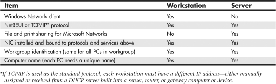
![]() For more information about Windows Vista/7 and networks, see “Networking with Windows Vista/7,” p. 911 (this chapter).
For more information about Windows Vista/7 and networks, see “Networking with Windows Vista/7,” p. 911 (this chapter).
Although the networking settings in Table 17.12 enable a Windows peer-to-peer network to function, you might need to add more networking components. If the computer can access a Novell NetWare client/server network running NetWare 4.x, the IPX/SPX protocol must also be installed. It also might be required for certain operations with NetWare 5. If the computer is used to access the Internet or any other TCP/IP-based network, the TCP/IP protocol must also be installed. In most cases, you can now use TCP/IP as the only network protocol because it can be used for both Internet and LAN access.
Use the Network icon in the Windows Control Panel to select your network settings. To set up your network, you’ll need the operating system CDs, disks, or hard-disk image files and the network adapter drivers. (Workgroup hubs and switches require no software.)
To install a network component, follow this procedure:
1. Open the Network icon in the Control Panel.
2. The Configuration tab is displayed; select Add.
3. Select from the following:
• Client—Select if you want to install the Microsoft or other network clients for your network. Every PC on a peer-to-peer network needs the Client for Microsoft Networks.
• Adapter—This should already be installed, but you can use this option to install a new adapter.
• Protocol—For a simple, non-Internet network with versions of Windows before XP, install NetBEUI. If you want to use Internet Connection Sharing along with networking, install both TCP/IP and NetBEUI. With Windows XP, use the Network Setup Wizard to configure TCP/IP easily.
• Service—Install File and Printer Sharing for Microsoft Networks on any computer that will be used as a server.
4. Click the Identification tab. Enter a unique name for each computer on the network; use the same workgroup name for all computers on the network.
5. Click OK. Supply the Windows CD-ROM or other media as necessary to install the network components you requested.
6. You are prompted to insert a CD or disk or to browse to the appropriate files during the installation procedure, if they’re not available on the Windows CD-ROM or on your hard disk in the default location.
You might need to reboot your PC to complete the process, particularly if you’re using Windows 9x or Me. After this is completed, you’ll be ready to share resources.
After the network hardware and software installation is complete, your network is ready to use. However, if you are using Windows NT, Windows 2000, or Windows XP Professional, you must set up users and groups for security. Windows 9x, Me, and Windows XP Home Edition use peer-to-peer access control, which can be protected with passwords if you desire.
For more information about these processes, see “Configuring Users, Groups, and Resources” in the Technical Reference section of the disc packaged with this book.
Networking with Windows Vista/7
Windows Vista/7 includes TCP/IP as its default protocol, enabling it to connect to other computers running Windows or other operating systems. However, its network management and configuration processes are much different from those used by earlier Windows versions.
Network management is performed through the new Network and Sharing Center. The Network and Sharing Center displays the status of the network, the signal strength for wireless networks, and the status of network discovery and the sharing of files, the Public folder (equivalent to the Shared Files folder in XP), printer sharing, and media sharing. The Network and Sharing Center can change these settings as desired and also controls whether password-protected sharing is enabled or disabled. When this feature is disabled, Vista/7 acts like Windows XP with simple file sharing enabled. When this feature is enabled, you must set up users and assign them rights just you would with Windows XP Professional with simple file sharing disabled.
The Network and Sharing Center can also provide a map of your network, showing the relationship of devices such as routers and switches and Windows Vista/7–based computers on the network. To add Windows XP–based systems to the network map, you can install the Link Layer Topology Discoverer (LLTD) responder. To get this feature and learn how it works, look up Knowledge Base article 922120, “Network Map does not display computers that are running Windows XP,” at http://support.microsoft.com.
To add a protocol or component to a particular network connection, open Networks, select Network and Sharing Center, and select Manage Network Connections from the task list. Right-click the network adapter and select Properties.
Other differences include enhancements in the use and management of wireless networks, improvements to the Windows Firewall, and improvements in the network repair and diagnostics procedure. Windows Vista/7 also add support for network projectors and online meetings, using its new People Near Me and Windows Meeting Space utilities.
Tips and Tricks
Network configuration can take a long time unless you have a few tricks up your sleeve. Use this section to help you find faster, easier, and better ways to set up and use your network.
Sharing Resources
• If you want to have network drives or folders automatically show up in Windows Explorer, map a drive letter to each one.
• To more easily keep drive mappings straight, I use the drive letter I plan to use for mapping on other workstations as the name of the shared resource on my peer server. In other words, if I want to map the D: drive on my peer server as “P:”, I name it “P” when I set its sharing properties. Then, as I view the folder from another computer, I know from its name that I should map it as “P:”. This enables multiple PCs to easily map the same resource as the same drive letter on different systems.
Setting Up Security
• If you’re building a peer-to-peer network, keep in mind that passwords are the only way to keep unwanted users out of your system. Windows XP Professional requires you to disable Simple File Sharing before you can set up users and groups. Windows XP Home Edition does not support passwords, making it the least secure peer server operating system of any recent Windows version.
• Create a group of several users and assign rights on a group basis when you have several users who need the same access rights.
Sharing Internet Connections
• Routers are an economical way to share broadband access in a home or small office, and they are easier to manage and more reliable than using Windows Internet Connection Sharing (ICS) or other sharing programs. Routers act as firewalls to protect your computer from unauthorized access from the Internet.