
Chapter 12. Video Hardware
Display Adapters and Monitors
Although the monitor (or video display) is as vital to a PC’s user interface as the mouse and keyboard, it is actually a latecomer to computing. Before CRT (cathode ray tube) monitors came into general use, the teletypewriter was the standard computer interface—a large, loud device that printed the input and output characters on a roll of paper. Early personal computers often used nothing more than a panel of blinking LEDs for a display.
The first monitors used on computers displayed only text in a single color (usually green), but to users at the time they were a great improvement, allowing real-time display of input and output data. Over time, color displays were introduced, screen sizes increased, and LCD technologies moved from the portable computer to the desktop. The latest trends reflect the increasing convergence of entertainment and computer technologies.
Although modern video hardware is much more sophisticated than that of the past, you should still be careful when selecting video hardware for your computer. A poor display can cause eyestrain or otherwise significantly diminish the experience of using your PC.
The video subsystem of a PC consists of two main components:
• Monitor (or video display)—The monitor is a display device usually based on an LCD panel, but may also use CRT, plasma, or DLP technology.
• Display adapter (also called the video card, graphics adapter, or graphics processing unit)—Although this usually refers to an adapter card plugged into a slot, the video adapter circuitry might also be built into the motherboard or included as part of the motherboard’s chipset. Although it sounds strange, the circuitry is still called an adapter or card even if it is fully integrated into the motherboard or chipset.
This chapter explores the range of PC video display adapters on the market today and the monitors that work with them.
Note
The term video, as it is used in this context, does not necessarily imply the existence of a moving image, such as on a television screen. Any circuitry that feeds signals to a monitor or display is a video display adapter, regardless of whether it is used with applications that display moving images, such as multimedia or videoconferencing software.
For this reason, video cards are sometimes referred to as graphics cards or display adapters.
Video Display Adapters
A video display adapter (aka video card) provides the interface between your computer and your monitor and transmits the signals that appear as images on the display. Throughout the history of the PC, there has been a succession of standards for video hardware that represents a steady increase in screen resolution, color depth, and performance. The following list of standards can serve as an abbreviated history of PC video-display technology:
MDA (Monochrome Display Adapter)
HGC (Hercules Graphics Card)
CGA (Color Graphics Adapter)
EGA (Enhanced Graphics Adapter)
VGA (Video Graphics Array)
SVGA (Super VGA)
XGA (Extended Graphics Array) and beyond
IBM pioneered most of these standards, but other manufacturers of compatible PCs adopted and enhanced them as well. Today, IBM no longer sets standards for the PC business (it even sold its PC business to Lenovo in 2005), and many of these standards are obsolete.
Today’s VGA and later video adapters can also handle most older software written for CGA, EGA, and other obsolete graphics standards. This enables you to use many, if not most, older graphics software (such as games and educational programs) on your current system.
Video Adapter Types
A monitor requires a source of input. The signals that run to your monitor come from one or more video display adapters in the system.
There are three basic types of video display adapters:
• Discrete plug-in video cards—These cards require the use of an expansion slot, but provide the highest possible level of features and performance.
• Discrete video on the motherboard—The same discrete circuitry that can be found on a video card can also be directly built in or mounted on the motherboard. This is how high-end video is installed in modern laptops and some older desktop systems; however, modern desktops normally use either discrete video on a plug-in card or motherboard chipset integrated video instead.
• Motherboard chipset integrated video—Integrated video shares the system RAM and other components. This has the lowest cost of any video solution, but performance can also be very low, especially for 3D gaming or other graphics-intensive applications. Resolution and color-depth options are also more limited than those available with add-on video cards. Because it is very economical on power, integrated video is used in many laptops for improved battery life. Many desktop systems with integrated video allow the installation of a discrete video plug-in card as an upgrade.
The term video adapter applies to either discrete or integrated video circuitry. The term graphics adapter is essentially interchangeable with video adapter because all video cards developed except the original IBM monochrome display adapter (MDA) can display graphics as well as text.
Integrated Video/Motherboard Chipsets
Although built-in video has been a staple of low-cost computing for a number of years, until the late 1990s most motherboard-based video simply mounted discrete video components on the motherboard. The performance and features of discrete video are essentially the same whether it is soldered into the motherboard or plugged in via an expansion card. In most cases the built-in discrete video could be upgraded by adding a video card. Some motherboard-based discrete video implementations also had provisions for memory upgrades.
However, in recent years the move toward increasing integration on the motherboard has led to the development of motherboard chipsets that include video support as part of the chipset design. In effect, the motherboard chipset takes the place of most of the discrete video card components and uses a portion of main system memory as video memory. The use of main system memory for video memory is often referred to as unified memory architecture (UMA), and although this memory-sharing method was also used by some built-in video that used its own chipset, it has become much more common with the rise of integrated motherboard chipsets.
Silicon Integrated Systems (SiS) pioneered chipsets with integrated video in 1996 and 1997 with its SiS5510 and SiS5596 chipsets for laptop and desktop systems, respectively. In 1997, Cyrix Semiconductor (now owned by VIA Technologies) introduced the MediaGX, which was the first to build both graphics and chipset functions into a PC-compatible CPU. National Semiconductor and later AMD developed improved versions of the MediaGX known as the Geode GX series.
Intel introduced motherboard chipsets with integrated graphics in 1999, starting with its 810 chipset for the Pentium III and Celeron processors. The 810 (codenamed Whitney) heralded the beginning of widespread industry support for this design, and the beginning of Intel’s dominance in the graphics market. Intel later followed the release of the 810 series (810 and 810E) with the 815 series for the Pentium III and Celeron, most of which also feature integrated video.
Since then, Intel has offered versions of both desktop and mobile chipsets with integrated graphics, and has become the world’s largest supplier of graphics chips virtually every year thereafter. This may sound strange because most people think of NVIDIA and ATI when it comes to graphics. Although NVIDIA and ATI may dominate in the high-end discrete graphics chip market, the market for lower-cost desktop and laptop systems with integrated graphics is larger than that for discrete graphics. Table 12.1 shows graphics chip market share data from JPR (Jon Peddie Research).
Table 12.1 Graphics Chip Market Share

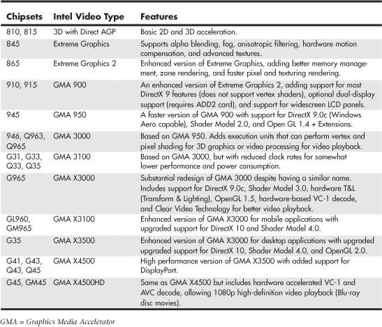
Table 12.2 shows the types and features for the integrated graphics available in Intel motherboard chipsets over the years.
Table 12.2 Intel Motherboard Chipset Integrated Video
Besides Intel, other major vendors of chipsets with integrated graphics include AMD/ATI, NVIDIA, SiS, and VIA/S3. Because there have been so many different chipsets with integrated video from these manufacturers over the years, I recommend consulting the specific manufacturer websites for more detailed information on specific chipset models and capabilities.
Newer integrated chipsets support digital outputs (such as DVI, HDMI, or DisplayPort) for use with digital LCD panels and home theater components. Figure 12.2, later in this chapter, illustrates how you can differentiate these ports.
Although a serious 3D gamer will not be satisfied with the performance of integrated graphics, business, home/office, and casual gamers will find that integrated chipset-based video on recent platforms is satisfactory in performance and provides significant cost savings compared with a separate video card. If you decide to buy a motherboard with an integrated chipset, I recommend that you select one that also includes a PCI Express x16 video expansion slot. This enables you to add a faster video card in the future if you decide you need it.
Video Adapter Components
Video display adapters contain certain basic components, usually including the following:
• Video BIOS.
• Video processor/video accelerator.
• Video memory.
• Digital-to-analog converter (DAC). Formerly a separate chip, the DAC is usually incorporated into the video processor/accelerator chip. The DAC is not necessary on a purely digital subsystem (digital video card and display); however, most display subsystems still include analog VGA support.
• Bus connector.
• Video driver.
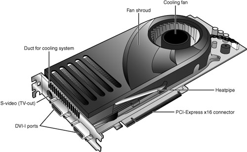
On high-performance video cards, such as the card shown in Figure 12.1, most of the components are underneath the cooling system. This card uses a combination of a fan and heatpipe to cool its graphics processing unit (GPU).
Figure 12.1 A typical example of a high-performance video card optimized for gaming and dual-display support.
Virtually all video adapters on the market today use chipsets that include 3D acceleration features. The following sections examine the video BIOS and processor in greater detail.
The Video BIOS
Video adapters include a BIOS that is separate from the main system BIOS. If you turn on your monitor first and look quickly, you might see an identification banner for your adapter’s video BIOS at the very beginning of the system startup process.
Similar to the system BIOS, the video adapter’s BIOS takes the form of a ROM (read-only memory) chip containing basic instructions that provide an interface between the video adapter hardware and the software running on your system. The software that makes calls to the video BIOS can be a standalone application, an operating system, or the main system BIOS. The programming in the BIOS chip enables your system to display information on the monitor during the system POST and boot sequences, before any other software drivers have been loaded from disk.
![]() See “BIOS Basics,” p. 313 (Chapter 5, “BIOS”).
See “BIOS Basics,” p. 313 (Chapter 5, “BIOS”).
In some cases the video BIOS also can be upgraded, just like a system BIOS. The video BIOS normally use a rewritable chip called an EEPROM (electrically erasable programmable read-only memory). On very old cards, you might be able to completely replace the chip with a new one—again, if supplied by the manufacturer and if the manufacturer did not hard-solder the BIOS to the printed circuit board. Most video cards use a surface-mounted BIOS chip rather than a socketed chip. A BIOS you can upgrade using software is referred to as a flash BIOS, and most video cards that offer BIOS upgrades use this method. However, because the video BIOS is only used during startup for VGA emulation, such upgrades are rarely necessary and most vendors fix problems by issuing updated drivers rather than BIOS updates.
Note
Video BIOS upgrades are sometimes referred to as firmware upgrades.
The Video Processor
The video processor (also known as the video chipset, video graphics processor, or GPU) is the heart of any video adapter and essentially defines the card’s functions and performance levels. Two video adapters built using the same chipset will have the same basic capabilities. However, cards built using the same chipset can vary in the clock speeds at which they run the chipset, memory, and other components, as well as in the amount and type of memory installed. Therefore, performance can vary. The software drivers that operating systems and applications use to address the video adapter hardware are written primarily with the chipset in mind. You can normally use a driver intended for an adapter with a particular chipset on any other adapter using the same chipset, or the same chipset families.
Identifying the Video and System Chipsets
Before you purchase a system or a video card, you should find out which chipset the video card or video circuit uses. For systems with integrated chipset video, you need to find out which integrated chipset the system uses. This allows you to have the following:
• A better comparison of the card or system to others
• Access to technical specifications
• Access to reviews and opinions
• The ability to make a better buying decision
• The choice of card manufacturer or chipset manufacturer support and drivers
Because video card performance and features are critical to enjoyment and productivity, find out as much as you can before you buy the system or video card by using the chipset or video card manufacturer’s website and third-party reviews. Poorly written or buggy drivers can cause several types of problems, so be sure to check periodically for video driver updates and install any that become available. With video cards, support after the sale can be important. Therefore, you should check the manufacturer’s website to see whether it offers updated drivers and whether the product seems to be well supported.
Note that although NVIDIA and AMD/ATI are the leading suppliers of discrete graphics processors, they do not normally make video cards. Instead, they create video card reference designs, which the various card manufacturers use to develop their own specific cards. Because each card manufacturer can customize or modify the designs as it chooses, two cards that use the same graphics chipset may differ in features as well as in actual performance. This means a wide variety of video cards use the same chipset; it also means you are likely to find variations in card performance, software bundles, warranties, and other features between cards using the same chipset.
Video RAM
Most discrete video adapters rely on their own onboard memory that they use to store video images while processing them. Systems with integrated video use the universal memory architecture (UMA) feature to share the main system memory. In any case, the memory on the video card or the memory borrowed from the system performs the same tasks.
The amount of video memory determines the maximum screen resolution and color depth the device can support, among other features. You often can select how much memory you want on a particular video adapter; for example, 256MB, 512MB, and 1GB are common choices today. Although having more video memory is not guaranteed to speed up your video adapter, it can increase the speed if it enables a wider bus (for example, from 128 bits wide to 256 bits wide) or provides nondisplay memory as a cache for commonly displayed objects. It also enables the card to generate more colors and higher resolutions and allows 3D textures to be stored and processed on the card, rather than in slower main memory.
Many types of memory have been used with video adapters. These memory types are summarized in Table 12.3.
Table 12.3 Memory Types Used in Video Display Adapters

Some of these, including FPM DRAM, EDO DRAM, and SDRAM, were also used for main memory in PCs. All of the others were specifically designed for use in graphics subsystems.
![]() For more information about FPM DRAM, EDO DRAM, and SDRAM, see Chapter 6, “Memory,” p. 375.
For more information about FPM DRAM, EDO DRAM, and SDRAM, see Chapter 6, “Memory,” p. 375.
VRAM and WRAM
VRAM and WRAM are dual-ported memory types that can read from one port and write data through the other port. This improves performance by reducing wait times for accessing the video RAM compared to FPM DRAM and EDO DRAM.
SGRAM
Synchronous Graphics RAM (SGRAM) was designed to be a high-end solution for very fast video adapter designs. SGRAM is similar to SDRAM in its capability to be synchronized to high-speed buses up to 200MHz, but it differs from SDRAM by including circuitry to perform block-writes to increase the speed of graphics fill and 3D Z-buffer operations.
DDR SGRAM
Double Data Rate SGRAM is designed to transfer data at speeds twice that of conventional SGRAM by transferring data on both the rising and falling parts of the processing clock cycle.
GDDR2 SGRAM
There have been several variations of what has been called GDDR2. The first was based on standard 2.5V DDR SDRAM with some enhancements, whereas the second was actually based on 1.8V DDR2 SDRAM, and with much higher performance and cooler operation.
GDDR3 SGRAM
GDDR3 SGRAM is based on DDR2 memory, but with two major differences:
• GDDR3 separates reads and writes with a single-ended unidirectional strobe, whereas DDR2 uses differential bidirectional strobes. This method enables higher data transfer rates.
• GDDR3 uses an interface technique known as pseudo-open drain, which uses voltage instead of current. This method makes GDDR3 memory compatible with GPUs designed to use DDR, GDDR2, or DDR2 memory. To determine the type of memory used on a particular video card, check the video card manufacturer’s specification sheet.
GDDR4 SGRAM
GDDR4 SGRAM is used by some of the newer cards. Compared to GDDR3, GDDR4 memory has the following features:
• Higher bandwidth. GDDR4 running at half the speed of GDDR3 provides comparable bandwidth to its predecessor.
• Greater memory density, enabling fewer chips to be needed to reach a particular memory size.
GDDR5 SGRAM
GDDR5 SGRAM is based on the previous GDDR standards with several modifications to allow increased performance. The main differences include the following:
• Signal optimization using data/address bit inversion, adjustable driver strength, adjustable voltage, and adjustable termination
• Adaptive interface timing using data training that is scalable per bit or byte
• Error compensation, including real-time error detection on both read/write and fast re-sending
GDDR5 is also designed for extreme power management such that power is only used when necessary. This allows higher clock speeds with cooler operation. Current GDDR5 parts are rated up to 7Gbps per chip, allowing 28GBps total bandwidth.
Video RAM Speed
Video RAM speed is typically measured in MHz, GHz, or by bandwidth in Mbits/Gbits or MBytes/GBytes per second. Faster memory and faster GPUs produce better gaming performance, but at a higher cost. However, if you are primarily concerned about business or productivity application performance, you can save money by using a video card with a slower GPU and slower memory.
Unless you dig deeply into the technical details of a particular graphics card, determining what type of memory a particular card uses can be difficult. Because none of today’s video cards feature user upgradeable memory, I recommend that you look at the performance of a given card and choose the card with the performance, features, and price that’s right for you.
RAM Calculations
The amount of memory a video adapter needs to display a particular resolution and color depth is based on a mathematical equation. A location must be present in the adapter’s memory array to display every pixel on the screen, and the resolution determines the number of total pixels. For example, a screen resolution of 1024×768 requires a total of 786,432 pixels.
If you were to display that resolution with only two colors, you would need only 1 bit of memory space to represent each pixel. If the bit has a value of 0, the dot is black, and if its value is 1, the dot is white. If you use 32 bits of memory space to control each pixel, you can display more than 4 billion colors because 4,294,967,296 combinations are possible with a 32-digit binary number (232=4,294,967,296). If you multiply the number of pixels necessary for the screen resolution by the number of bits required to represent each pixel, you have the amount of memory the adapter needs to display that resolution. Here is how the calculation works:

As you can see, displaying 32-bit color (4,294,967,296 colors) at 1024×768 resolution requires exactly 3MiB of RAM on the video adapter. Because most adapters have memory installed in multiples of 2, you would need to use a video adapter with at least 4MiB of RAM onboard to run your system using that resolution and color depth.
To use the higher-resolution modes and greater numbers of colors common today, you would need much more memory on your video adapter than the 256KB found on the original IBM VGA. Using the same calculation, even at a relatively high resolution of 1920x1080 (HDTV) using 32-bit color on a modern video card requires only need 7.91MiB, meaning only 8MiB would be required on the card. Since most modern video cards have 128MiB or more, you can see that two-dimensional images don’t require much memory.
3D video cards require more memory for a given resolution and color depth because the video memory must be used for three buffers: the front buffer, back buffer, and Z-buffer. The amount of video memory required for a particular operation varies according to the settings used for the color depth and Z-buffer. Triple buffering allocates more memory for 3D textures than double buffering but can slow down the performance of some games. The buffering mode used by a given 3D video card usually can be adjusted through its properties sheet.
Although current integrated graphics solutions feature 3D support, the performance they offer is limited by being based on older, less powerful 3D GPUs and by the narrow data bus they use to access memory. Because integrated graphics solutions share video memory with the processor, they use the same data bus as the processor. In a single-channel-based system, this restricts the data bus to 64 bits. A dual-channel system has a 128-bit data bus, but today’s fastest 3D video cards feature a 512-bit or wider data bus. The wider the data bus, the more quickly graphics data can be transferred.
For these reasons, you are likely to be disappointed (and lose a lot of games!) if you play 3D games using integrated graphics. To enjoy 3D games, opt for a mid-range to high-end 3D video card based on a current ATI or NVIDIA chipset with 256MB of RAM or more. If your budget permits, you might also consider using a multicard solution from ATI or NVIDIA that allows you to use two or more PCI-Express video cards to increase your graphics processing performance.
![]() See “Dual-GPU Scene Rendering,” p. 706 (this chapter).
See “Dual-GPU Scene Rendering,” p. 706 (this chapter).
Note
If your system uses integrated graphics and you have less than 256MB of RAM, you might be able to increase your available graphics memory by upgrading system memory (system memory is used by the integrated chipset). Some Intel chipsets with integrated graphics automatically detect additional system memory and adjust the size of graphics memory automatically.
Video Memory Bus Width
Another issue with respect to the memory on the video adapter is the width of the bus connecting the graphics chipset and memory on the adapter. The chipset is usually a single large chip on the card that contains virtually all the adapter’s functions. It is wired directly to the memory on the adapter through a local bus on the card. Most of the high-end adapters use an internal memory bus that is up to 512 bits wide (or more in some cases). This jargon can be confusing because video adapters that take the form of separate expansion cards also plug into the main system bus, which has its own speed rating. When you read about a 256-bit or 512-bit video adapter, you must understand that this refers to the memory connection on the card, not the connection to the motherboard. In two cards with otherwise similar GPU, memory type, and memory size specifications, the card with the wider memory bus is preferable because a wider memory bus boosts performance.
![]() See “System Bus Types, Functions, and Features,” p. 269 (Chapter 4, “Motherboards and Buses”).
See “System Bus Types, Functions, and Features,” p. 269 (Chapter 4, “Motherboards and Buses”).
The Digital-to-Analog Converter (DAC)
The digital-to-analog converter on a video adapter (commonly called a DAC or RAMDAC) does exactly what its name describes. The RAMDAC is responsible for converting the RAM-based digital images your computer generates into signals for analog monitor connections. The speed of the RAMDAC is measured in MHz; the faster the conversion process, the higher the adapter’s vertical refresh rate. The speeds of the RAMDACs used in today’s high-performance video adapters range from 300MHz to 500MHz. Most of today’s video card chipsets include the RAMDAC function inside the 3D accelerator chip, but some dual-display-capable video cards use a separate RAMDAC chip to allow the second display to work at different refresh rates than the primary display. Systems that use integrated graphics include the RAMDAC function in the North Bridge or GMCH chip portion of the motherboard chipset.
The benefits of increasing the RAMDAC speed include higher vertical refresh rates, which allow higher resolutions with flicker-free refresh rates (72Hz–85Hz or above). Typically, cards with RAMDAC speeds of 300MHz or above display flicker-free (75Hz or above) at all resolutions up to 1920×1200. Of course, as discussed earlier in this chapter, you must ensure that any resolution you want to use is supported by both your monitor and video card.
Video Display Interfaces
Video display adapters connect a PC to a display and therefore must work through two main interfaces. The first is the system interface, meaning the connection between the video adapter and the PC, and the second is the display interface, meaning the connection between the video adapter and the display. By using standardized versions of these interfaces, we end up having video adapters and displays that are both compatible and easily interchangeable. This section discusses the available system and display interfaces as well as the differences between them.
The System Interface
Older video adapters were designed for use with earlier bus standards, such as the IBM MCA, ISA, EISA, and VL-Bus. Because of their relatively slow performance by today’s standards, all are now obsolete. Current video display adapters use the PCI, AGP, or PCI-Express interface standards to connect to a system.
In current systems, PCI Express is the most popular video card slot (in 16-lane or x16 form), replacing the long-time standard AGP 8x. Older PCI video cards are more limited in performance and are sold primarily as add-ons or upgrades for older systems. For example, one common upgrade is to add a second video card to run dual (or more) monitors, which often requires a PCI based video card, even if the primary card is AGP based.
![]() See “The PCI Bus,” p. 286 (Chapter 4).
See “The PCI Bus,” p. 286 (Chapter 4).
![]() See “PCI Express,” p. 290 (Chapter 4).
See “PCI Express,” p. 290 (Chapter 4).
![]() See “Accelerated Graphics Port,” p. 292 (Chapter 4).
See “Accelerated Graphics Port,” p. 292 (Chapter 4).
Accelerated Graphics Port (AGP)
The Accelerated Graphics Port (AGP), an Intel-designed dedicated video bus introduced in 1997, delivers a maximum bandwidth up to 16 times greater than that of a comparable PCI bus. AGP was the mainstream high-speed video-to-system interface for several years but has been replaced by the more versatile and faster PCI Express standard.
The AGP slot is essentially an enhancement to the existing PCI bus; however, it’s intended for use only with video adapters and provides them with high-speed access to the main system memory array. This enables the adapter to process certain 3D video elements, such as texture maps, directly from system memory rather than having to copy the data to the adapter memory before the processing can begin. This saves time and eliminates the need to upgrade the video adapter memory to better support 3D functions. Although AGP version 3.0 provides for two AGP slots, this feature has never been implemented in practice. Systems with AGP have only one AGP slot.
Note
Although the earliest AGP cards had relatively small amounts of onboard RAM, most later implementations use large amounts of on-card memory and use a memory aperture (a dedicated memory address space above the area used for physical memory) to transfer data more quickly to and from the video card’s own memory. Integrated chipsets featuring built-in AGP use system memory for all operations, including texture maps.
Windows 98 and later versions support AGP’s Direct Memory Execute (DIME) feature. DIME uses main memory instead of the video adapter’s memory for certain tasks to lessen the traffic to and from the adapter. However, with the large amounts of memory found on current AGP video cards, this feature is seldom implemented.
Four speeds of AGP are available: 1x, 2x, 4x, and 8x (see Table 12.4 for details). Later AGP video cards support AGP 8x and can fall back to AGP 4x or 2x on systems that don’t support AGP 8x.
Table 12.4 AGP Speeds and Technical Specifications
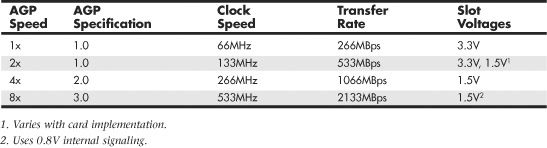
AGP 3.0 was announced in 2000, but support for the standard required the development of motherboard chipsets that were not introduced until mid-2002. Almost all motherboard chipsets with AGP support released after that time featured AGP 8x support.
Although some systems with AGP 4x or 8x slots use a universal slot design that can handle 3.3V or 1.5V AGP cards, others do not. If a card designed for 3.3V (2x mode) is plugged into a motherboard that supports only 1.5V (4x mode) signaling, the motherboard may be damaged.
![]() See “Accelerated Graphics Port,” p. 292 (Chapter 4).
See “Accelerated Graphics Port,” p. 292 (Chapter 4).
Caution
Be sure to check AGP compatibility before you insert an older (AGP 1x/2x) card into a recent or current system. Even if you can physically insert the card, a mismatch between the card’s required voltage and the AGP slot’s voltage output can damage the motherboard. Check the motherboard manual for the card types and voltage levels supported by the AGP slot.
Some AGP cards can use either 3.3V or 1.5V voltage levels, adjusted via an onboard jumper. These cards typically use an AGP connector that is notched for use with either AGP 2x or AGP 4x slots, as pictured in Chapter 4. Be sure to set these cards to use 1.5V before using them in motherboards that support only 1.5V signaling.
PCI Express (PCIe)
PCI Express began to show up in systems in mid-2004 and has filtered down to almost all systems that use discrete video cards or have integrated video that can be upgraded. Despite the name, PCI Express uses a high-speed bidirectional serial data transfer method, and PCI Express channels (also known as lanes) can be combined to create wider and faster expansion slots (each lane provides 250MBps, 500MBps, or 1,000MBps data rate in each direction). Because PCI Express is technically not a bus, unlike PCI the slots do not compete with each other for bandwidth. PCI Express graphics cards use up to 16 lanes (x16) to enable speeds of 4GBps, 8GBps, or 16GBps in each direction, as seen in Table 12.5.
Table 12.5 PCI Express Video Card Bandwidth

Most PCI Express implementations include one x16 slot for video and two or more x1 slots for other add-on cards, as well as legacy PCI slots. Systems that support NVIDIA’s SLI or ATI’s CrossFire dual PCI Express video card technologies have up to three or four PCI Express video slots running at x8 or x16 speed.
The Display Interface
The display interface is used to connect the video display adapter to the monitor or display. Over the years, several different methods of connecting monitors have been available. Some of these interfaces have been analog, and others have been digital.
The very early PC video standards used from 1981 through the late 1980s were based on crude (by today’s standards) digital interface designs. These included the original MDA (Monochrome Display Adapter), CGA (Color Graphics Adapter), and EGA (Enhanced Graphics Adapter) standards. The CGA and EGA in particular generated different colors by sending digital color signals down three wires, which allowed for the display of up to eight colors (23). Another signal doubled the number of color combinations from eight to 16 by allowing each color to display at two intensity levels. This type of digital display was easy to manufacture and offered simplicity, with consistent color combinations from system to system. The main drawback of the early digital display standards was the limited number of possible colors.
Unlike earlier digital video standards, VGA (Video Graphics Array) is an analog system. VGA came out in 1987 and began a shift from digital to analog that lasted for more than 20 years. Only recently has there been a shift back to digital. Why go from digital to analog and then back to digital? The simple answer is that analog was the least expensive way at the time to design a CRT based system that supported a reasonable resolution with a reasonable number of colors. Now that technology has advanced and LCD panels have largely replaced CRTs, going back to digital interfaces makes sense.
The video interfaces (and connectors) you are likely to encounter in PCs dating from the late ’80s to the present include the following:
VGA (Video Graphics Array)
DVI (Digital Visual Interface)
HDMI (High-Definition Multimedia Interface)
DisplayPort
VGA is an analog connection, while the others are digital. The connectors for these interfaces are shown in Figure 12.2.
Figure 12.2 Video interface connectors used in PCs from the late ’80s to the present.

The following section focuses on these display interfaces.
Video Graphics Array (VGA)
IBM introduced the Video Graphics Array (VGA) interface and display standard on April 2, 1987, along with a family of systems it called PS/2. VGA originally included the display adapter, the monitor, and the connection between them. Since that time the display adapters and monitors have evolved, but the VGA 15-pin analog connection went on to become the most popular video interface in history, and is still used today in PC video adapters and displays.
VGA is an analog design. Analog uses a separate signal for each CRT color gun, but each signal can be sent at varying levels of intensity—64 levels, in the case of the original VGA standard. This provides 262,144 possible colors (643), of which 256 could be simultaneously displayed in the original design. For realistic computer graphics, color depth is often more important than high resolution because the human eye perceives a picture that has more colors as being more realistic.
VGA was designed to be addressed through the VGA BIOS interface, a software interface that forced programs to talk to the BIOS-based driver rather than directly to the hardware. This allowed programs to call a consistent set of commands and functions that would work on different hardware, as long as a compatible VGA BIOS interface was present. The original VGA cards had the BIOS on the video card directly, in the form of a ROM chip containing from 16KB to 32KB worth of code. Modern video cards and laptop graphics processors still have this 32KB onboard BIOS. Typically, the only time the ROM-based drivers are used is during boot, when running legacy DOS-based applications or games, or when you run Windows in Safe Mode.
VGA also describes a 15-pin analog interface connection that can support a wide variety of modes. The connection is analog because VGA was primarily designed to drive CRT displays, which are analog by nature. When a display is connected via VGA, the digital signals inside the PC are converted to analog signals by the DAC (Digital-to-Analog Converter) chip in the display adapter and are then sent to the display via the analog VGA connection. The VGA connector is shown in Figure 12.3; the pinouts are shown in Table 12.6.
Figure 12.3 The standard 15-pin analog VGA connector.

Table 12.6 15-Pin Analog VGA Connector Pinout
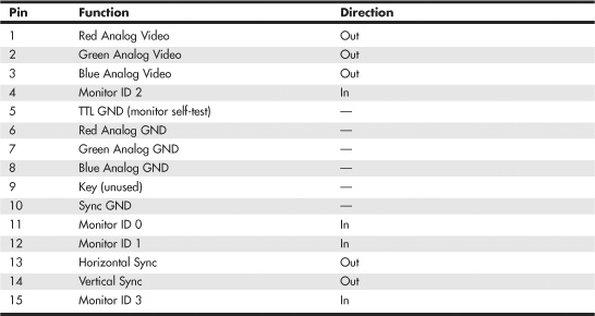
The mating VGA cable connector that plugs into this connector normally has pin 9 missing. This was designed such that the mating hole in the connector on the video card could be plugged, but it is usually open (and merely unused) instead. The connector is keyed by virtue of the D-shape shell and pin alignment, so it is difficult to plug in backward even without the key pin. Pin 5 is used only for testing purposes, and pin 15 is rarely used; they are often missing as well. To identify the type of monitor connected to the system, some early VGA cards used the presence or absence of the monitor ID pins in various combinations.
In addition to the connector and electrical interface, the original VGA standard also defined a number of text and graphics display modes with various resolutions and colors. The original VGA modes allowed for a maximum graphics resolution of 640×480 in only 16 (4-bit) colors. This was the maximum that could be supported by the original 256KB of RAM included on the card.
IBM introduced higher-resolution versions of VGA called XGA and XGA-2 in the early 1990s, but most of the development of VGA standards has come from the third-party video card industry and its trade group, the Video Electronic Standards Association (VESA).
When VGA originated in 1987, it had very low resolution and color capability by today’s standards. Since then, VGA has evolved to support higher resolution modes with many more colors. Even the least-expensive video adapters on the market today can work with modes well beyond the original VGA standard.
SVGA and XGA
The original IBM VGA card was quickly cloned by other video card manufacturers. To distinguish their products from the IBM original, many provided additional modes and capabilities, generically calling them “Super” VGA or SVGA cards.
By 1989, competing video card and display manufacturers had wanted to cooperate in order to make the new SVGA capabilities an industry standard as well as make them compatible with existing software and hardware designed for VGA.
In February 1989, an international nonprofit group called Video Electronics Standards Association (VESA) was formed to create industrywide interface standards for the PC and other computing environments. VESA was designed to create and promote open standards for the display and display interface industry, which would ensure interoperability and yet also allow for innovation. VESA is led by a board of directors that represents a voting membership of more than 100 corporate members worldwide. The members are PC hardware, software, display, and component manufacturers, as well as cable and telephone companies, service providers, and more. VESA essentially took the role of defining PC video interface standards away from IBM, giving it instead to the VESA members.
In August 1989, VESA introduced its first standard, an 800×600 4-bit (16-color) BIOS interface standard called Super VGA (SVGA) mode 6Ah, which was the maximum that could be supported by the original 256KB of RAM included on early VGA cards. This allowed companies to independently develop video hardware having a common software interface, thus allowing for higher resolution functionality while maintaining interchangeability and backward compatibility with existing VGA. Shortly thereafter, VESA extended the SVGA standard with other modes and resolutions, and it developed or contributed to many successive standards in PC video.
Note
Although SVGA technically defines a set of VESA standards that includes modes from 800×600 and beyond, typically we use the term SVGA to describe only the 800×600 mode. Other higher-resolution modes have been given different names (XGA, SXGA, and so on), even though they are technically part of the VESA SVGA specifications.
IBM further increased the RAM as well as the available resolutions and colors when it introduced the XGA (eXtended Graphics Array) standard in 1990. XGA was basically an enhanced version of VGA, with more memory (1MB), enhanced resolution, color content, and increased hardware functionality. XGA was also optimized for Windows and other graphical user interfaces. The most exciting feature XGA added to VGA was support for two new graphics modes:
• 1024×768 256-color mode
• 640×480 256-color mode
Notably missing from IBM’s original XGA interface was the VESA-defined SVGA 800×600 16-color mode, which had debuted just over a year earlier. That was important because not many monitors at the time could handle 1024×768, but many could handle 800×600. With IBM’s card you had to jump from 640×480 directly to 1024×768, which required a very expensive monitor back then. That oversight was finally corrected when IBM released XGA-2 in 1992. XGA-2 added more performance and additional color depth, as well as support for the mid-range SVGA 800×600 VESA modes:
• 640×480 256- and 65,536-color modes
• 800×600 16-, 256-, and 65,536-color modes
• 1024×768 16- and 256-color modes
Since then, VESA and other industry groups have defined all the newer video interface and display standards. IBM became a member of VESA and many of the other groups as well.
Digital Display Interfaces
The analog VGA interface works well for CRTs, which are inherently analog devices, but VGA does not work well for LCD, plasma, or other types of flat-panel displays that are inherently digital. Video data starts out digitally inside the PC and is converted to analog when the VGA interface is used. When you are running a digital display such as an LCD over an analog interface such as VGA, the signal must then be converted back to digital before it can be displayed, resulting in a double conversion that causes screen artifacts, blurred text, color shifting, and other kinds of problems.
Using a digital interface eliminates the double conversion, allowing the video information to remain as digital data from the PC all the way to the screen. Therefore, a trend back to using digital video interfaces has occurred, especially for inherently digital displays such as LCD flat panels.
Laptop computers have avoided this problem by using an internal digital connection called FPD-Link (Flat Panel Display-Link), which was originally developed by National Semiconductor in 1995. Unfortunately, this standard was not designed for external connections requiring longer cable lengths or extremely high resolutions. What was needed was an industry standard digital connection for external displays.
In order to facilitate a digital video connection between PCs and external displays, several digital video signal standards and specifications have been available:
• Plug and Display (P&D)
• Digital Flat Panel (DFP)
• Digital Visual Interface (DVI)
• High Definition Multimedia Interface (HDMI)
• DisplayPort
The Plug and Display (P&D) and Digital Flat Panel (DFP) standards were released by the Video Electronic Standards Association (VESA) in June 1997 and February 1999, respectively. Both were based on the PanelLink TMDS (Transition Minimized Differential Signaling) protocol developed by Silicon Image. Unfortunately, both of these interfaces had relatively low-resolution support (1280×1024 maximum) and were only implemented in a handful of video cards and monitors. As such, they never really caught on in the mass market and were both overshadowed by the Digital Visual Interface (DVI), which become the first truly popular digital display interface standard.
DVI
The Digital Visual Interface (DVI) was introduced on April 2, 1999 by the Digital Display Working Group (DDWG). The DDWG was formed in 1998 by Intel, Silicon Image, Compaq, Fujitsu, Hewlett-Packard, IBM, and NEC to address the need for a universal digital interface standard between a host system and a display. Unlike the P&D and DFP interfaces that came before it, DVI gained immediate widespread industry support, with 150 DVI products being shown at the Intel Developer Forum in August 1999, only four months after DVI was released. Since then, DVI has become the most popular interface for digital video connections. DVI also allows for both digital and VGA analog connections using the same basic connector.
DVI uses Transition Minimized Differential Signaling (TMDS), which was developed by Silicon Image (www.siliconimage.com) and trademarked under the name PanelLink. TMDS takes 24-bit parallel digital data from the video controller and transmits it serially over balanced lines at a high speed to a receiver. A single-link TMDS connection uses four separate differential data pairs, with three for color data (one each for red, green, and blue data) and the fourth pair for clock and control data. Each twisted pair uses differential signaling with a very low 0.5V swing over balanced lines for reliable, low-power, high-speed data transmission. A low-speed VESA Display Data Channel (DDC) pair is also used to transmit identification and configuration information, such as supported resolution and color-depth information, between the graphics controller and display.
TMDS is designed to support cables up to 10 meters (32.8 feet) in length, although the limits may be shorter or longer depending on cable quality. Several companies make products that can amplify or re-drive the signals, allowing for greater lengths. Figure 12.4 shows a block diagram of a single-link TMDS connection.
Figure 12.4 A single-link TMDS connection.

Using TMDS, each color channel (red/green/blue) transmits 8 bits of data (encoded as a 10-bit character) serially at up to 165MHz. This results in a raw throughput of 1.65Gbps per channel. There are three color channels per link, resulting in a maximum raw bandwidth of 4.95Gbps per link. Because the data is sent using 8b/10b encoding, only 8 bits of every 10 are actual data, resulting in a maximum true video data throughput of 3.96Gbps. This enables a single-link DVI connection to easily handle computer video resolutions as high as WUXGA (1920×1200) as well as 1080p HDTV (1920×1080 with progressive scan).
If more bandwidth is necessary, the DVI standard supports a second TMDS link in the same cable and connector. This uses three additional TMDS signal pairs (one for each color) and shares the same clock and DDC signals as the primary link. This is called dual-link DVI, and it increases the maximum raw bandwidth to 9.9Gbps and the true data bandwidth to 7.92Gpbs, which will handle computer resolutions as high as WQUXGA (3840×2400). Normally only 30″ or larger flat-panel displays use resolutions high enough to require dual-link DVI. Even higher resolution displays can be supported with dual DVI ports, each with a dual-link connection.
TMDS links include support for Display Data Channel (DDC), a low-speed, bidirectional standard for communication between PCs and monitors, created by the VESA. DDC defines the physical connection and signaling method, whereas the communications and data protocol is defined under the VESA Extended Display Identification Data (EDID) standard. DDC and EDID allow the graphics controller to identify the capabilities of the display so the controller can automatically configure itself to match the display’s capabilities.
DVI uses Molex MicroCross connectors with several variations. The DVI standard was primarily designed to support digital devices; however, for backward compatibility, it can also support analog devices as well. The DVI-D (digital) connector supports only digital devices, whereas the DVI-I (integrated) connector supports both digital and analog devices via the addition of extra pins. Figure 12.5 and Table 12.7 show the DVI-I (integrated) connector and pinout.
Figure 12.5 The DVI-I connector.

Table 12.7 DVI-I Connector Pinout

The DVI-D connector is the same as the DVI-I connector, except that it lacks the analog connections. By virtue of the unique MicroCross connector design, a digital-only device can connect only to receptacles with digital support, and an analog-only device can plug in only to receptacles with analog support. This design feature ensures that an analog-only device cannot be connected to a digital-only receptacle, and vice versa. Figure 12.6 shows the DVI-D connector. The pinout is the same as the DVI-I connector, except for the missing analog signals. The DVI-D connector is widely used on laptop port replicators and docking stations that provide DVI support.
Figure 12.6 The DVI-D connector.

The DVI-I connector shown in Figure 12.5 can be converted into a VGA port for use with CRTs or with analog LCD panels via a simple adapter. Often new graphics cards purchased at retail that support only DVI come with just such an adapter that allows you to connect a traditional VGA connector from the display to the adapter.
Unfortunately the Digital Display Working Group (DDWG) that created DVI has disbanded, leaving DVI frozen in time at the DVI 1.0 specification level. This means that DVI will not be updated in the future. Although it has enjoyed tremendous popularity as the first widely used digital display interface, the PC industry as a whole is moving to DisplayPort as the replacement for DVI.
HDMI
The High Definition Multimedia Interface (HDMI) was designed by a group of multimedia companies (Hitachi, Panasonic, Philips, Silicon Image, Sony, Thomson, and Toshiba) as a way to provide a single-cable connection for transporting digital video and audio signals between consumer electronics hardware such as big-screen TVs, video games, DVD players, and home theater systems. HDMI was introduced in December 2002, and version 1.3a was introduced in November 2006.
HDMI is basically a superset of DVI and uses the same TMDS (Transition Minimized Differential Signaling) as does DVI. Unlike DVI, however, each color channel also carries multiplexed audio data. HDMI 1.2a and earlier supports a maximum data clock rate of 165MHz, sending 10 bits per cycle, or 1.65Gbps per channel. There are three channels per link, resulting in a maximum raw bandwidth of 4.95Gbps. Because the data is sent using 8b/10b encoding, only 8 bits of every 10 are actual data, resulting in a true data throughput of 3.96Gbps. This enables a single-link HDMI 1.2a or earlier connection to easily handle computer video resolutions as high as WUXGA (1920×1200) as well as 1080p HDTV (1920×1080 with progressive scan) plus audio data.
HDMI 1.3 increases the maximum clock rate to 340MHz, resulting in 10.2Gbps raw bandwidth, or a true data throughput of 8.16Gbps. This increase allows a single-link HDMI connection to have slightly more throughput than a dual-link DVI connection, which handles computer resolutions as high as WQUXGA (3840×2400) plus audio data.
HDMI can also carry up to eight channels of uncompressed digital audio at 24-bit/192KHz along with Dolby Digital, DTS, Dolby TrueHD, and DTS-HD Master Audio compressed audio formats. Because it uses a single cable for both audio and video signals, HDMI provides an excellent way to reduce the cabling tangle present in home theater systems that use conventional analog audio and video cables. For home theater users who subscribe to HDTV satellite or cable services, HDMI is ideal because it supports high-bandwidth digital content protection (HDCP), which these services use to protect content from piracy while still assuring high-quality viewing and listening. To avoid reduced-quality playback of protected content, all devices (including the DVD player or set-top box, AV receiver, and display) must support HDCP.
In addition to transmitting high-quality audio and video between devices, HDMI carries additional signals. HDMI uses the display data channel (DDC) to identify the capabilities of an HDMI display, such as resolutions, color depth, and audio. DDC enables optimal playback quality on different devices. HDMI also supports the optional consumer electronic control (CEC) feature, which enables one-button control of all CEC-enabled devices for one-touch play or record or other features.
Table 12.8 compares the HDMI versions.

Because HDMI is essentially a superset of DVI, it is backward-compatible with DVI as well. This means that using a simple and inexpensive adapter, you can connect an HDMI source to a DVI display as well as connect a DVI source to an HDMI display. However, unless both the source and monitor both support HDCP, you might not be able to play premium HDTV content, or the resolution might be reduced. Although some graphics cards claimed HDCP support as early as the first part of 2006, changes in the HDCP standard may prevent early cards from working properly. You should contact your graphics card and monitor vendor to determine whether a particular device supports HDCP.
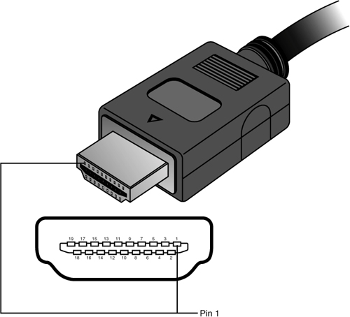
Current HDMI cables correspond to HDMI Type A or Type C. Type A is a 19-pin connector. Type C is a smaller version of Type A, designed for use in DV camcorders or other portable devices. It uses the same pinout, and Type A–to–Type C adapters are available from various vendors. HDMI version 1.0 also defined a 29-pin Type B dual-link cable that has not been used in any products.
Figure 12.7 illustrates a typical HDMI Type A cable and the location of pin 1 on the cable and connector.
Figure 12.7 HDMI Type A cable and socket use a two-row 19-pin interface.
The pinout for HDMI Type A and Type C cables is shown in Table 12.9.
Table 12.9 HDMI Type A/Type C Connector Pinout
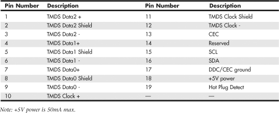
Figure 12.8 illustrates a typical HDMI-DVI adapter cable.
Figure 12.8 HDMI–DVI adapter cable.

Note
The adapter cable shown in Figure 12.8 is not designed to work with graphics cards and drivers that do not support HDTV resolutions and timings. You may need to upgrade your graphics card driver before using an HDMI-DVI cable. Although some set-top boxes include DVI ports, this type of adapter cable is only intended for PC-HDTV connections.
Starting in late 2006, some vendors began to release PCI-Express cards including HDMI ports. Some provide HDMI input and output for use with HDV camcorders, while others using ATI or NVIDIA chipsets are graphics cards that also include HDMI output. Unfortunately, HDMI is a royalty-based interface, requiring an annual license fee of $10,000 plus a payment of 4 cents per device. This plus the requirements for additional circuitry in both graphics cards and displays has helped to keep HDMI as more of a consumer electronics (i.e. home entertainment) interface, while DVI and DisplayPort are far more popular in PCs as a video display interface.
For more information about HDMI, see the HDMI Founders website at www.hdmi.org.
DisplayPort
DisplayPort is the latest digital display interface standard. It is designed to replace VGA, DVI, and HDMI for use in PCs and to coexist with HDMI in consumer electronics devices. Dell originated the design in 2003 and then turned it over to the Video Electronics Standards Association (VESA) in August 2005. In May 2006, VESA published it as an open industry standard.
DisplayPort is designed to replace all the previous digital and analog interfaces, including DVI, HDMI, and even VGA. In addition, it is a royalty-free interface and does not incur the licensing fees of HDMI or the implementation patent fees of DVI. In addition, DisplayPort is designed both as an internal and an external interface, meaning it can replace the FPD-Link (Flat Panel Display-Link) interface used internally in most laptops. In short, DisplayPort is designed to be the ultimate universal display interface for PCs now as well as in the future.
Previous digital display interfaces such as DVI and HDMI use TMDS (Transition Minimized Differential Signaling), which requires extra logic on both the source and display ends, logic that must usually be licensed from Silicon Image. DisplayPort instead uses a packetized (network-like) interface that can easily be implemented in chipsets without the extra cost logic required for DVI or HDMI. DisplayPort is kind of like a high-speed Ethernet for video, and the network-like design allows for features such as multiple video streams over a single connection, which means you can connect multiple displays to a single port.
Because it is a license-free, royalty-free design, DisplayPort has seen rapid adoption throughout the industry. In fact, all new chipsets and GPUs since 2008 from Intel, NVIDIA, and AMT/ATI already have integrated DisplayPort support. In 2008, major manufacturers including Dell, HP/Compaq, Lenovo, and Apple introduced products with DisplayPort and endorsed DisplayPort as the successor to DVI and HDMI for most digital display connections.
On the technical side, DisplayPort is a high-speed serial interface with up to four main data lanes (differential signal pairs) carrying multiplexed video and audio data, each of which supports a raw data rate of 1.62Gbps, 2.7Gbps, or 5.4Gbps (DisplayPort 1.2 or later only). Using all four lanes results in a maximum raw bandwidth of 6.48Gbps, 10.8Gbps, or 21.6Gbps, respectively. Because 8b/10b encoding is used, only 8 bits of every 10 are data, resulting in maximum true data throughputs of 5.184Gbps, 8.64Gbps, or 17.28Gbps, respectively.
Audio is optional, with support for up to eight channels of 16- or 24-bit linear PCM data at a 48KHz, 96KHz, or 192KHz sampling rate, with an uncompressed maximum audio bandwidth of 6.144Mbps.
DisplayPort 1.1 includes the following features:
• Small external connectors (slightly larger than USB size) with optional latching. Four display connectors can fit on a single PCIe expansion card bracket and fit easily in laptops.
• Cable lengths of up to 15 meters (49′), which allows for remote displays or projectors.
• Micro-packet network architecture over one to four lanes. Connections can use only as many lanes as necessary for reduced wire counts.
• High performance. A true data bandwidth of 8.64Gbps (four lanes at 2.16Gbps per lane) allows WQXGA 2560×1600 resolution.
• Support for internal (embedded) as well as external LCD connections. This allows a universal interface for both desktop and laptop systems.
• Optional audio that supports displays with built-in speakers.
• Optional HDCP (High-bandwidth Digital Content Protection) to allow playing protected media.
• Interoperability with DVI and HDMI over a DisplayPort connector. You can connect to DVI or HDMI with simple and inexpensive adapters.
• An auxiliary 1Mbps channel, which allows for two-way communication for integrated cameras, microphones, and so on.
• A powered connector, which powers some LCD displays directly.
• An optional latching connector that uses a simple thumb-press release design with no bolts or jackscrews.
DisplayPort 1.2 is fully backward compatible with 1.1 and adds the following features:
• Double the performance. DisplayPort 1.2 offers 21.6Gbps raw (17.28Gbps true) bandwidth, which is more than twice that of HDMI 1.3a and nearly triple that of DVI.
• Multiple data streams, which allows support for two WQXGA 2560×1600 or four WUXGA 1920×1200 monitors daisy-chained over a single cable.
• An auxiliary channel speed increase to 480Mbps. This allows USB 2.0 speed connections for cameras, microphones, or other devices.
• The Mini DisplayPort connector. This connector is approximately half the size yet provides full functionality for laptops or other devices where space is at a premium.
Table 12.10 compares the versions of DisplayPort.
Table 12.10 DisplayPort Versions

The DisplayPort connector has 20 pins and is only slightly larger than USB size (15.9mm vs. 12mm wide). The pins consist of four data lanes (differential pairs), an auxiliary channel (differential pair), plus configuration and power pins. Figures 12.9 and 12.10 show the DisplayPort cable/plug and socket.
Figure 12.9 DisplayPort cable with latching plug connector (Belkin).
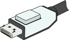
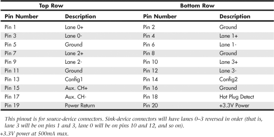
Figure 12.10 DisplayPort socket and pin configuration.

Apple introduced the Mini DisplayPort connector in October 2008, which was subsequently included as part of the official DisplayPort standard in 1.2 and later releases. The Mini DisplayPort connector has the same full complement of 20 pins as the standard DisplayPort connector, but it’s about half the size (at only 7.4mm wide). Figures 12.11 and 12.12 show the Mini DisplayPort cable/plug and socket. Table 12.11 shows the DisplayPort socket connector pinout.
Figure 12.11 Mini DisplayPort cable and plug (Apple).

Figure 12.12 Mini DisplayPort socket and pin configuration.

Table 12.11 DisplayPort Socket Connector Pinout
VESA has created several icons and logos associated with DisplayPort. The basic DisplayPort icon is used to label products incorporating DisplayPort technology, whereas the DisplayPort Certification Compliance logo is used on product marketing material to indicate devices that have been tested to ensure they are fully interoperable with other DisplayPort devices. Figure 12.13 shows the DisplayPort Certification Compliance logo. VESA maintains a list of certified devices on the www.displayport.org website.
Figure 12.13 DisplayPort Certification Compliance logo (left).

The DisplayPort Multimode icon adds two “+” symbols to indicate a port or device that is fully backward compatible with both DVI and HDMI technology (via inexpensive cable adapters). Figure 12.14 shows the DisplayPort Multimode icon. Figure 12.15 shows an inexpensive DisplayPort to DVI adapter.
Figure 12.14 Icon indicating a DisplayPort with Multimode (DVI and HDMI) support (right).

Figure 12.15 DisplayPort to DVI adapter, which works on MultiMode DisplayPort connectors.

When DisplayPort was first released, many people wondered why we needed another digital display interface when we already had DVI and HDMI. Those interfaces unfortunately carry both technical and licensing limitations that were preventing their universal adoption. DisplayPort is designed to overcome not only the technical limitations, but especially the licensing constraints and fees that the other interfaces brought along as baggage. The advanced technical capabilities of DisplayPort, combined with the elimination of licensing and its backward compatibility with existing interfaces, are likely to ensure its rapid adoption throughout the PC marketplace.
TV Display Interfaces
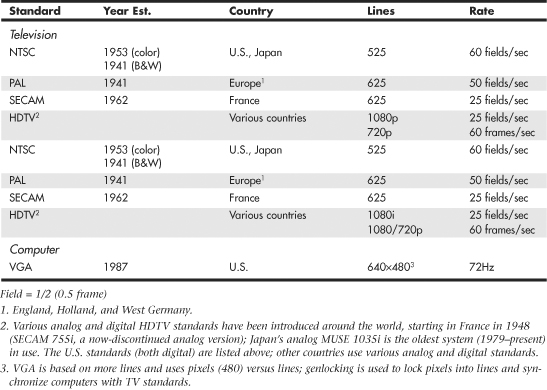
When video technology first was introduced, it was based on television. However, a difference exists between the signals used by a television and those used by a computer monitor. In the United States, the National Television System Committee (NTSC) established color TV standards in 1953. Some other countries, such as Japan, followed this standard. Many countries in Europe, though, developed more sophisticated standards, including Phase Alternate Line (PAL) and Sequential Couleur Avec Mémoire (SECAM). Table 12.12 shows the differences among these standards.
Table 12.12 Television Versus Computer Monitors
A video-output adapter enables you to display computer screens on a TV set or record them onto videotape for easy distribution. These products fall into two categories: those with genlocking (which enables the board to synchronize signals from multiple video sources or video with PC graphics) and those without. Genlocking provides the signal stability necessary to obtain adequate results when recording to tape, but it isn’t necessary for using a television as a video display.
Video converters are available as internal expansion boards, external boxes that are portable enough to use with a laptop for presentations on the road, and, most commonly today, TV-out ports on the rear of most video cards using chipsets from NVIDIA, ATI, and others. Most converters support the standard NTSC television format and might also support the European PAL format. The resolution these devices display on a TV set or record on videotape often is limited to VGA (640×480) or SVGA (800×600) resolution.
To connect your PC to an HDTV monitor, it is preferable to use a digital signal via a DVI, HDMI, or DisplayPort connection. If your current video adapter only has analog VGA output, you’ll want to upgrade to a video adapter with a DVI, HDMI, or DisplayPort digital output. Because most HDTVs use HDMI, if your video card has DVI or DisplayPort, you can use a DVI-to-HDMI or DisplayPort-to-HDMI adapter if necessary. If you need HDCP support for watching HD premium content, make sure your display and card support HDCP. Otherwise, you may not be able to watch the program or it may be displayed at reduced resolution.
3D Graphics Accelerators
Since the late 1990s, 3D acceleration—once limited to exotic add-on cards designed for hardcore game players—has become commonplace in the PC world. With the introduction of the Aero desktop in Windows Vista and later, 3D imaging is even utilized in the user interface, joining other full-motion 3D uses such as sports, first-person shooters, team combat, driving, and many other types of PC gaming. Because even low-cost integrated chipsets offer some 3D support, virtually any user of a recent-model computer has the ability to enjoy 3D lighting, perspective, texture, and shading effects.
Note
At a minimum, enabling the Windows Aero interface in Vista and later requires graphics hardware that supports DirectX 7 3D graphics; however, for maximum functionality, graphics hardware that supports DirectX 9 or greater is required. Games are now being released that require DirectX 10, which is not available for Windows XP and earlier versions.
How 3D Accelerators Work
To construct an animated 3D sequence, a computer can mathematically animate the sequences between keyframes. A keyframe identifies a specific point. A bouncing ball, for example, can have three keyframes: up, down, and up. Using these frames as reference points, the computer can create all the interim images between the top and bottom. This creates the effect of a smoothly bouncing ball.
After it has created the basic sequence, the system can then refine the appearance of the images by filling them in with color. The most primitive and least effective fill method is called flat shading, in which a shape is simply filled with a solid color. Gouraud shading, a slightly more effective technique, involves the assignment of colors to specific points on a shape. The points are then joined using a smooth gradient between the colors.
A more processor-intensive (and much more effective) type of fill is called texture mapping. The 3D application includes patterns—or textures—in the form of small bitmaps that it tiles onto the shapes in the image, just as you can tile a small bitmap to form the wallpaper for your Windows desktop. The primary difference is that the 3D application can modify the appearance of each tile by applying perspective and shading to achieve 3D effects. When lighting effects that simulate fog, glare, directional shadows, and others are added, the 3D animation comes very close indeed to matching reality.
Until the late 1990s, 3D applications had to rely on support from software routines to convert these abstractions into live images. This placed a heavy burden on the system processor in the PC, which has a significant impact on the performance not only of the visual display, but also of any other applications the computer might be running. Starting in the period from 1996 to 1997, chipsets on most video adapters began to take on many of the tasks involved in rendering 3D images, greatly lessening the load on the system processor and boosting overall system performance.
There have been roughly 10 generations of 3D graphics hardware on PCs, a process that has lasted over a decade, as detailed in Table 12.13.
Table 12.13 Brief History of 3D Acceleration

With virtually every recent graphics card on the market featuring DirectX 9 or greater capabilities, you don’t need to spend a fortune to achieve a reasonable level of 3D graphics. Many cards in the $50–$150 range use lower-performance variants of current high-end GPUs, or they might use the previous year’s leading GPU. These cards typically provide more-than-adequate performance for 2D business applications. Most current 3D accelerators also support dual-display and TV-out capabilities, enabling you to work and play at the same time.
However, keep in mind that the more you spend on a 3D accelerator card, the greater the onboard memory and faster the accelerator chip you can enjoy. If money is no object, and you are a hardcore gamer, you can buy a graphics card featuring its fastest GPU for more than $500. Fortunately, there are plenty of choices using either NVIDIA or ATI GPUs in the under-$500 price range that still offer plenty of 3D gaming performance, including support for dual-GPU operations (NVIDIA SLI or ATI CrossFire), which split rendering chores across the GPUs in both video cards for faster game display than with a single card. GPUs that support DirectX 10 are the preferred choice for a serious gamer who wants to play the newest games.
Mid-range cards costing $100–$300 are often based on GPUs that use designs similar to the high-end products but might have slower memory and core clock speeds or a smaller number of rendering pipelines. These cards provide a good middle ground for users who play games fairly often but can’t cost-justify high-end cards.
Before purchasing a 3D accelerator adapter, you should familiarize yourself with some of the terms and concepts involved in the 3D image generation process.
The basic function of 3D software is to convert image abstractions into the fully realized images that are then displayed on the monitor. The image abstractions typically consist of the following elements:
• Vertices—Locations of objects in three-dimensional space, described in terms of their x, y, and z coordinates on three axes representing height, width, and depth.
• Primitives—The simple geometric objects the application uses to create more complex constructions, described in terms of the relative locations of their vertices. This serves not only to specify the location of the object in the 2D image, but also to provide perspective because the three axes can define any location in three-dimensional space.
• Textures—Two-dimensional bitmap images or surfaces designed to be mapped onto primitives. The software enhances the 3D effect by modifying the appearance of the textures, depending on the location and attitude of the primitive. This process is called perspective correction. Some applications use another process, called MIP mapping, which uses different versions of the same texture that contain varying amounts of detail, depending on how close the object is to the viewer in the three-dimensional space. Another technique, called depth cueing, reduces the color and intensity of an object’s fill as the object moves farther away from the viewer.
Using these elements, the abstract image descriptions must then be rendered, meaning they are converted to visible form. Rendering depends on two standardized functions that convert the abstractions into the completed image that is displayed onscreen. The standard functions performed in rendering are as follows:
• Geometry—The sizing, orienting, and moving of primitives in space and the calculation of the effects produced by the virtual light sources that illuminate the image
• Rasterization—The converting of primitives into pixels on the video display by filling the shapes with properly illuminated shading, textures, or a combination of the two
A modern video adapter that includes a chipset capable of 3D video acceleration has special built-in hardware that can perform the rasterization process much more quickly than if it were done by software (using the system processor) alone. Most chipsets with 3D acceleration perform the following rasterization functions right on the adapter:
• Scan conversion—The determination of which onscreen pixels fall into the space delineated by each primitive
• Shading—The process of filling pixels with smoothly flowing color using the flat or Gouraud shading technique
• Texture mapping—The process of filling pixels with images derived from a 2D sample picture or surface image
• Visible surface determination—The identification of which pixels in a scene are obscured by other objects closer to the viewer in three-dimensional space
• Animation—The process of switching rapidly and cleanly to successive frames of motion sequences
• Antialiasing—The process of adjusting color boundaries to smooth edges on rendered objects
Typical 3D Techniques
Typical 3D techniques include the following:
• Fogging—Fogging simulates haze or fog in the background of a game screen and helps conceal the sudden appearance of newly rendered objects (buildings, enemies, and so on).
• Gouraud shading—Interpolates colors to make circles and spheres look more rounded and smooth.
• Alpha blending—One of the first 3D techniques, alpha blending creates translucent objects onscreen, making it a perfect choice for rendering explosions, smoke, water, and glass. Alpha blending also can be used to simulate textures, but it is less realistic than environment-based bump mapping.
• Stencil buffering—Stencil buffering is a technique useful for games such as flight simulators in which a static graphic element—such as a cockpit windshield frame, which is known as a heads-up display (HUD) and used by real-life fighter pilots—is placed in front of dynamically changing graphics (such as scenery, other aircraft, sky detail, and so on). In this example, the area of the screen occupied by the cockpit windshield frame is not re-rendered. Only the area seen through the “glass” is re-rendered, saving time and improving frame rates for animation.
• Z-buffering—The Z-buffer portion of video memory holds depth information about the pixels in a scene. As the scene is rendered, the Z-values (depth information) for new pixels are compared to the values stored in the Z-buffer to determine which pixels are in “front” of others and should be rendered. Pixels that are “behind” other pixels are not rendered. This method increases speed and can be used along with stencil buffering to create volumetric shadows and other complex 3D objects. Z-buffering was originally developed for computer-aided drafting (CAD) applications.
• Environment-based bump mapping—Environment-based bump mapping (standard starting in DirectX 6) introduces special lighting and texturing effects to simulate the rough texture of rippling water, bricks, and other complex surfaces. It combines three separate texture maps (for colors; for height and depth; and for environment, including lighting, fog, and cloud effects). This creates enhanced realism for scenery in games and can also be used to enhance terrain and planetary mapping, architecture, and landscape-design applications. This represents a significant step beyond alpha blending.
• Displacement mapping—Special grayscale maps called displacement maps have long been used for producing accurate maps of the globe. Microsoft DirectX 9 and 10 support the use of grayscale hardware displacement maps as a source for accurate 3D rendering. GPUs that fully support DirectX 9 and 10 in hardware support displacement mapping.
Advanced 3D Filtering and Rendering
To improve the quality of texture maps, several filtering techniques have been developed, including MIP mapping, bilinear filtering, trilinear filtering, and anisotropic filtering. These techniques and several other advanced techniques found in recent 3D GPUs are explained here:
• Bilinear filtering—Improves the image quality of small textures placed on large polygons. The stretching of the texture that takes place can create blockiness, but bilinear filtering applies a blur to conceal this visual defect.
• MIP mapping—Improves the image quality of polygons that appear to recede into the distance by mixing low-res and high-res versions of the same texture. This is a form of antialiasing.
• Trilinear filtering—Combines bilinear filtering and MIP mapping, calculating the most realistic colors necessary for the pixels in each polygon by comparing the values in two MIP maps. This method is superior to either MIP mapping or bilinear filtering alone.
Note
Bilinear and trilinear filtering work well for surfaces viewed straight on, but might not work so well for oblique angles (such as a wall receding into the distance).
• Anisotropic filtering—Some video card makers use another method, called anisotropic filtering, for more realistically rendering oblique-angle surfaces containing text. This technique is used when a texture is mapped to a surface that changes in two of three spatial domains, such as text found on a wall down a roadway (for example, advertising banners at a raceway). The extra calculations used take time, and for that reason it can be disabled. To balance display quality and performance, you can also adjust the sampling size: Increase the sampling size to improve display quality or reduce it to improve performance.
• T-buffer—This technology eliminates aliasing (errors in onscreen images due to an undersampled original) in computer graphics, such as the “jaggies” seen in onscreen diagonal lines; motion stuttering; and inaccurate rendition of shadows, reflections, and object blur. The T-buffer replaces the normal frame buffer with a buffer that accumulates multiple renderings before displaying the image. Unlike some other 3D techniques, T-buffer technology doesn’t require rewriting or optimization of 3D software to use this enhancement. The goal of T-buffer technology is to provide a movie-like realism to 3D-rendered animations. The downside of enabling antialiasing using a card with T-buffer support is that it can dramatically impact the performance of an application. This technique originally was developed by now-defunct 3dfx. However, it is incorporated into Microsoft DirectX 8.0 and above.
• Integrated transform and lighting (T&L)—The 3D display process includes transforming an object from one frame to the next and handling the lighting changes that result from those transformations. T&L is a standard feature of DirectX starting with version 7. The NVIDIA GeForce 256 and original ATI Radeon were the first GPUs to integrate the T&L engines into the accelerator chip, a now-standard feature.
• Full-screen antialiasing—This technology reduces the jaggies visible at any resolution by adjusting color boundaries to provide gradual, rather than abrupt, color changes. Whereas early 3D products used antialiasing for certain objects only, recent accelerators from NVIDIA and ATI use various types of highly optimized FSAA methods that allow high visual quality at high frame rates.
• Vertex skinning—Also referred to as vertex blending, this technique blends the connection between two angles, such as the joints in an animated character’s arms or legs.
• Keyframe interpolation—Also referred to as vertex morphing, this technique animates the transitions between two facial expressions, allowing realistic expressions when skeletal animation can’t be used or isn’t practical.
• Programmable vertex and pixel shading—Programmable vertex and pixel shading became a standard part of DirectX starting with version 8.0. However, NVIDIA introduced this technique with the GeForce3’s nfiniteFX technology, enabling software developers to customize effects such as vertex morphing and pixel shading (an enhanced form of bump mapping for irregular surfaces that enables per-pixel lighting effects), rather than applying a narrow range of predefined effects. DirectX 8- and 9-based GPUs use separate vertex and pixel shaders, but DirectX 10 supports a new architecture permitting unified shaders that can perform both vertex and pixel shading on a demand-driven basis.
• Floating-point calculations—Microsoft DirectX 9 and above support floating-point data for more vivid and accurate color and polygon rendition. In DirectX 9, vertex shaders used 32-bit precision, whereas pixel shaders used 24-bit precision. However, Shader Model 3.0 (DirectX 9.0c) increased pixel shader precision to 32-bit, the same precision used by DirectX 10’s unified shader design.
Single- Versus Multiple-Pass Rendering
Various video card makers handle the application of these advanced rendering techniques differently. The current trend is toward applying the filters and basic rendering in a single pass rather than in multiple passes. Video cards with single-pass rendering and filtering typically provide higher frame-rate performance in 3D-animated applications and avoid the problems of visible artifacts caused by errors in multiple floating-point calculations during the rendering process. Single-pass rendering in standard in DirectX 9 and 10.
Hardware Acceleration Versus Software Acceleration
Compared to software-only rendering, hardware-accelerated rendering provides faster animation. Although most software rendering would create more accurate and better-looking images, software rendering is too slow. Using special drivers, these 3D adapters can take over the intensive calculations needed to render a 3D image that software running on the system processor formerly performed. This is particularly useful if you are creating your own 3D images and animation, but it is also a great enhancement to the many modern games that rely extensively on 3D effects. Note that motherboard-integrated video solutions typically have significantly lower 3D performance than even low-end GPUs because they use the CPU for more of the 3D rendering than 3D video adapter chipsets do.
To achieve greater performance, many of the latest 3D accelerators run their accelerator chips at very high speeds, and many even allow overclocking of the default RAMDAC frequencies. Just as CPUs at high speeds produce a lot of heat, so too do high-speed video accelerators. Both the chipset and the memory are heat sources, so most mid-range and high-end 3D accelerator cards feature a fan to cool the chipset. Also, most current high-end 3D accelerators use cooling shrouds and fans to cool the memory chips and make overclocking the video card easier (refer to Figure 12.1).
Software Optimization
It’s important to realize that the presence of an advanced 3D-rendering feature on any given video card is meaningless unless game and application software designers optimize their software to take advantage of the feature. Although various 3D standards exist (OpenGL and DirectX), video card makers provide drivers that make their games play with the leading standards. Because some cards do play better with certain games, you should read the reviews in publications such as Maximum PC to see how your favorite graphics card performs with them. Typically, it can take several months or longer after a new version of DirectX or OpenGL is introduced before 3D games take full advantage of the 3D rendering features provided by the new API.
Some video cards allow you to perform additional optimization by adjusting settings for OpenGL, Direct 3D, RAMDAC, and bus clock speeds, as well as other options. Note that the bare-bones 3D graphics card drivers provided as part of Microsoft Windows usually don’t provide these dialog boxes. Be sure to use the drivers provided with the graphics card or download updated versions from the graphics card vendor’s website.
Application Programming Interfaces
Application programming interfaces (APIs) provide hardware and software vendors a means to create drivers and programs that can work quickly and reliably across a wide variety of platforms. When APIs exist, drivers can be written to interface with the API rather than directly with the operating system and its underlying hardware.
Currently, the leading game APIs include SGI’s OpenGL and Microsoft’s Direct3D (part of DirectX). OpenGL and Direct3D are available for virtually all leading graphics cards. At one time, a third popular game API was Glide, an enhanced version of OpenGL that is restricted to graphics cards that use 3dfx chipsets, which are no longer on the market.
OpenGL
The latest version of OpenGL is version 2.1, released on August 2, 2006. OpenGL 2.1 includes the core features of OpenGL 2.0—the OpenGL shading language (now in revision 1.20), programmable vertex and fragment shaders, multiple render targets—and adds support for non-square matrices, pixel buffer objects, sRGB textures, non-power-of-two textures, point sprites, and separate stencils for the front and back faces of graphics primitives.
Although OpenGL is a popular gaming API, it is also widely used in 3D rendering for specialized business applications, including mapping, life sciences, and other fields. Windows XP and newer can support OpenGL either through software or through hardware acceleration. For a particular graphics card to support hardware acceleration of OpenGL, the driver developer must include an installable client driver (ICD). The ICD is distributed as part of the driver package provided by the video card or GPU vendor. Thus, driver updates can improve OpenGL performance as well as DirectX (Direct3D) performance.
To learn more about OpenGL, see the OpenGL website at www.opengl.org.
Microsoft DirectX 9.0c, 10, and 11
Direct3D is part of Microsoft’s comprehensive multimedia API, DirectX. Although the most recent versions of DirectX (9.0c and up) provide support for higher-order surfaces (converting 3D surfaces into curves), vertex shaders, and pixel shaders, significant differences exist between DirectX versions in how these operations are performed.
DirectX 9.0c uses separate pixel and vertex shaders to create 3D objects. Although DirectX 9.0c provides greater precision in data handling as well as support for more instructions, more textures, and more registers than its predecessors, its use of separate shaders can still lead to slow 3D rendering when more pixels must be rendered than shaders, or vice versa. Shader Model 3 (used by DirectX 9.0c) is simply a development of the split-function design first developed for Shader Model 1 (used by DirectX 8.0) back in 2001, adding support for more instructions and greater numerical accuracy.
DirectX 10, developed for Windows Vista, includes a completely rebuilt Direct3D rendering engine with a brand-new shader design, Shader Model 4. Shader Model 4 adds a geometry shader to the vertex shader and pixel shader design used in earlier shader models to improve the handling of real-time scene changes such as explosions. However, the biggest single change in Shader Model 4 is the use of unified shaders that can be switched between vertex, pixel, and geometry shader operations on the fly, eliminating bottlenecks and improving performance, no matter what types of 3D data exist in a scene.
Note
With the replacement of dedicated vertex and pixel shaders in the DirectX 10 3D rendering pipeline, DirectX 10 GPUs are rated in terms of the number of stream processors on board. Each stream processor performs vertex, geometry, and pixel shading as needed.
When you are comparing two otherwise-equal DirectX 10 GPUs (same GPU, memory size and speed, motherboard and memory bus designs), the GPU with a larger number of stream processors will be faster.
Other architectural changes in DirectX 10 include process optimizations to reduce the load on the CPU. In a sample of different types of images rendered, DirectX 10 reduced the command cycles by as much as 90% over DirectX 9.
DirectX 11 was originally developed for Windows 7, and has several new features:
• Tesselation—provides additional pipeline stages that increase the number of visible polygons at runtime.
• Multithreaded rendering—enables the execution of Direct3D commands on multiple processor cores.
• Compute shaders—provides an additional stage independent of the Direct3D pipeline that enables general purpose computing on the graphics processor.
• Dynamic shader linkage—a limited runtime shader linkage that allows for improved shader specialization during application execution.
A version of DirectX 11 will also be available for Windows Vista.
It’s important to realize that DirectX 10/11 GPUs retain full compatibility with DirectX 9.0c and earlier DirectX versions, so you can play the latest games as well as old favorites with a DX10 or DX11-compliant video card. Updates for DirectX are provided via www.windowsupdate.com. More information about DirectX is available from Microsoft at www.microsoft.com/directx.
Dual-GPU Scene Rendering
In Table 12.15, I placed the development of dual PCI Express graphics card solutions as the ninth generation of 3D acceleration. The ability to connect two cards together to render a single display more quickly isn’t exactly new: The long-defunct 3dfx Voodoo 2 offered an option called scan-line interfacing (SLI), which pairs two Voodoo 2 cards together on the PCI bus with each card writing half the screen in alternating lines. With 3dfx’s version of SLI, card number one wrote the odd-numbered screen lines (one, three, five, and so on), while card number two wrote the even-numbered screen lines (two, four, six, and so on). Although effective, use of SLI with Voodoo 2 was an expensive proposition that only a handful of deep-pocketed gamers took advantage of.
A few companies also experimented with using multiple GPUs on a single card to gain a similar performance advantage, but these cards never became popular. However, the idea of doubling graphics performance via multiple video cards has proven too good to abandon entirely, even after 3dfx went out of business.
NVIDIA SLI
When NVIDIA bought what was left of 3dfx, it inherited the SLI trademark and, in mid-2004, reintroduced the concept of using two cards to render a screen under the same acronym. However, NVIDIA’s version of SLI has a different meaning and much more intelligence behind it.
NVIDIA uses the term SLI to refer to scalable link interface. The scaling refers to load-balancing, which adjusts how much of the work each card performs to render a particular scene, depending on how complex the scene is. To enable SLI, the following components are needed:
• A PCI Express motherboard with an SLI-compatible chipset and two PCI Express video slots designed for SLI operation
• Two NVIDIA-based video cards with SLI support
Note
Originally, you needed to use two identical cards for NVIDIA SLI. With the introduction of NVIDIA ForceWare v81.85 and higher driver versions, this is no longer necessary. Just as with the ATI CrossFire multi-GPU solution, the cards need to be from the same GPU family, but they don’t need to be from the same manufacturer. You can obtain updated drivers from your video card maker or from the NVIDIA website (www.nvidia.com).
In most cases, a special bridge device known as a multipurpose I/O (MIO) is used to connect the cards to each other. The MIO is supplied with SLI-compatible motherboards, but some SLI-compatible cards don’t use it.
To learn more about SLI and for a list of SLI-compatible GPUs and nForce motherboard chipsets, visit NVIDIA’s SLI Zone (http://sg.slizone.com).
Figure 12.16 illustrates a typical SLI hardware configuration. Note the MIO device connecting the cards to each other.
Figure 12.16 NVIDIA SLI installation using a multipurpose I/O (MIO) bridge device.

ATI CrossFire/CrossFireX
ATI’s CrossFire (now called CrossFireX) multi-GPU technology uses three methods to speed up display performance: alternate frame rendering, supertiling (which divides the scene into alternating sections and uses each card to render parts of the scene), and load-balancing scissor operation (similar to SLI’s load-balancing). The ATI Catalyst driver uses alternate frame rendering for best performance, but automatically switches to one of the other modes for games that don’t work with alternate frame rendering.
To achieve better image quality than with a single card, CrossFire offers various SuperAA (antialiasing) modes, which blend the results of antialiasing by each card. CrossFire also improves anisotropic filtering by blending the filtering performed by each card.
To use CrossFire, you need the following components:
• A PCI Express motherboard with a CrossFire-compatible chipset and two PCI Express video slots designed for CrossFire operation
• A supported combination of ATI CrossFire-supported cards
Note
For specific models of motherboards, video cards, power supplies, memory, and cases designed to support CrossFire, see http://ati.amd.com/crossfire.
First-generation CrossFire cards required users to buy special CrossFire Edition cards that contained the composting engine (an Xilinx XC3S400 chip) and used a proprietary DMS-59 port for interconnecting the cards. One of these cards was paired with a standard Radeon card from the same series via a clumsy external cable between the CrossFire Edition’s DMS port and the DVI port on the standard card. Newer CrossFire-compatible cards use the PCI Express bus or a CrossFire bridge interconnect (similar in concept to the SLI MIO component) to connect matching cards.
CrossFire can be disabled to permit multimonitor operation, and CrossFire cards can also be used to implement physics effects in games that use the HavokFX physics technology (www.havok.com).
For more information about CrossFire, see the AMD website at http://ati.amd.com/crossfire.
3D Chipsets
Virtually every mainstream video adapter in current production features a 3D acceleration-compatible chipset from vendors such as ATI (AMD), NVIDIA, and Matrox. With several generations of 3D adapters on the market from the major vendors, keeping track of the latest products can be difficult. Consult the chipset vendors’ websites for the latest information about the chipsets they offer, as well as third-party video card sources using a specific chipset.
Monitors
The monitors typically used with PCs come in a wide variety of sizes and resolutions, and are typically based on one of two display technologies: liquid crystal display (LCD) or cathode-ray tube (CRT). Larger displays such as big-screen TVs and projectors can also use LCD technology, but may use plasma or digital light processing (DLP) technology as well. This section discusses the various features, specifications, and technologies used in PC monitors.
Display Specifications
There are a number of features and specifications that differentiate one display from another. Some of these can be confusing, and some are more important than others. The following sections examine the features and specifications to look for when comparing or selecting displays.
Display Size
PC monitors come in various sizes, generally ranging from 15″ to 30″ in diagonal measurement. Displays smaller than 15″ are available for specialized uses (and are often used on smaller laptop or palmtop/netbook systems). Displays larger than 30″ are also available; however, these are generally categorized as large format multimedia displays or televisions rather than as PC monitors. In general, the larger the monitor, the higher the price tag; however, there are often “sweet spots” where a certain size may have a price advantage over smaller sizes due to sales and manufacturing popularity.
Display sizes are measured diagonally, which is an artifact from the round tubes used in the first televisions, where the diagonal measurement was equal to the physical diameter of the tube. Whereas the diagonal display size measures the physical size of the display, the viewable image size refers to the diagonal measurement of the usable area on the screen (for example, the operating system desktop). On an LCD panel, the physical diagonal measurement and the viewable image size of the display are the same. With CRTs, however, the viewable image size is typically 1″ smaller than the advertised diagonal display size. Therefore, when you’re comparing LCDs and CRTs with the same diagonal size, the LCD will actually offer a larger viewable image.
Note
Many people became upset when they realized that the CRT monitors they were buying displayed images that were smaller than the advertised number. For example, a 17″ CRT monitor would display only a 16″-sized image. This came to a head in the mid-1990s when several class-action lawsuits forced CRT monitor manufacturers to disclose the viewable image size in the immediate proximity of the physical diagonal measurement in any advertisements and specifications. LCDs were not affected by these lawsuits because LCDs have always had a viewable image size that is the same as the diagonal display measurement.
Tip
Larger, higher-resolution monitors retain their value longer than most other computer components. Although it’s common for a newer, faster processor to come out right after you have purchased your computer or to find the same model with a bigger hard disk for the same money, a good monitor can outlast your computer. If you purchase monitors with longer term usage considerations in mind, you can save money on your next system by reusing your existing monitor.
Resolution
Resolution indicates the amount of detail a monitor can render. This quantity is expressed in the number of horizontal and vertical picture elements, or pixels, contained in the screen. The total is usually expressed in the millions of pixels, or megapixels. As the resolution increases, the image consists of a greater number of pixels. With more pixels, you can see more of a given image and/or the image can be viewed in greater detail.
As PC video technology has evolved, available resolutions have grown at a steady pace. Table 12.14 shows the industry standard resolutions (from lowest to highest) used in PC graphics adapters and displays as well as the terms or designations commonly used to describe them.
Table 12.14 Graphics Display Resolution Standards
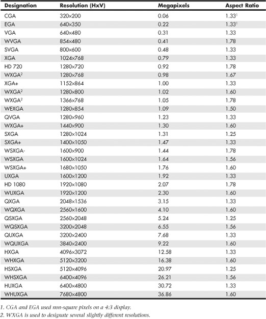
Display adapters normally support a variety of resolutions; however, what a display can handle is usually much more limited. Therefore, the specific resolution you use is normally dictated by the display, not the adapter. A given video adapter and display combination will usually have an allowable maximum (usually dictated by the display), but it can also work at several different resolutions less than the maximum. Because LCD monitors are designed to run at a single native resolution, they must use electronics to scale the image to other choices. Older LCD panels handled scaling poorly, but even though current LCD panels perform scaling fairly well, you are almost always better off selecting the single specific resolution that is native to the display you are using. However, if the native resolution of the display is exceptionally high, you can choose lower resolutions in order to achieve larger and more readable icons and text.
Aspect Ratio
A given resolution has a horizontal and vertical component, with the horizontal component the larger of the two. The aspect ratio of a display is the ratio between the horizontal and vertical number of pixels. It is calculated as the width (in pixels) divided by the height. A number of different aspect ratios have been used in PC displays over the years. Most of the early display formats were only slightly wider than they were tall. More recently, wider formats have become popular. Aspect ratios of 1.5 or higher (numerically) are considered “widescreen” displays. Originally 1.33 (4:3) was the most common aspect ratio for displays because it matched the aspect ratio of the original standard definition televisions. More recently, however, 1.60 (16:10 or 8:5) has become the most popular ratio for widescreen PC displays, whereas 1.78 (16:9) is the most popular format for widescreen televisions. Table 12.15 shows the various aspect ratios and designations.
Table 12.15 Standard Aspect Ratios and Designations
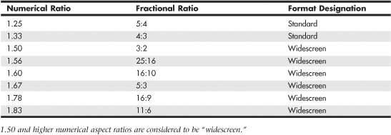
Figure 12.17 shows the physical difference between the most common standard and widescreen aspect ratio display formats.
Figure 12.17 Standard (4:3 or 1.33) versus widescreen (16:10 or 1.60) display aspect ratios.

Pixels
In a color monitor, each picture element (pixel) consists of three red, green, and blue (RGB) subpixels. By varying the intensity of each of the subpixels, you can cause the overall color and brightness of the pixel to be anything from black (all off) to white (all on) and almost any color or level in between. The physical geometry of the RGB subpixels varies depending on the type of display, but the shape is normally either rectangular stripes or round dots. LCD monitors normally have the three subpixels arranged as rectangular vertical stripes in a linear repeating arrangement. CRTs may also use linear stripes, or they can have staggered stripes or dot triads.
When you’re choosing a display, the most important considerations are the combination of size and resolution. The overall combination of size and resolution is normally expressed in pixels per inch (ppi), but it can also be expressed in pixel pitch, which is the distance between pixels in millimeters. A higher ppi number (or lower pixel pitch) means that fixed size images such as icons and text will be smaller and possibly harder to read. Pixel pitch is also sometimes called dot pitch, in reference to the dot shaped subpixels used on some displays.
For a given size screen, higher resolution displays have a higher ppi number, which corresponds to a lower pixel pitch number. As a result, the picture elements are closer together, producing a sharper picture onscreen. Conversely, screens with a lower ppi number (which equals a larger pixel/dot pitch) tend to produce images that are more grainy and less clear.
Figure 12.18 illustrates a dot-shaped subpixel arrangement most commonly found on shadow-mask base CRTs, where the pixel or dot pitch is the shortest distance between same color subpixels.
Figure 12.18 Dot-shaped subpixels, where pixel or dot pitch is the shortest distance between same color subpixels.
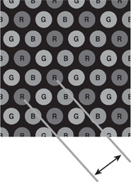
Figure 12.19 and 12.20 show striped subpixel arrangements in both linear and staggered forms. Of these, the linear form is the most common, used on virtually all LCDs and most aperture grille–based CRTs. With striped subpixels, the pitch is measured as the horizontal or vertical distance between same color subpixels.
Figure 12.19 Stripe-shaped subpixels in a linear arrangement, where pixel pitch is the distance between same color subpixel stripes.
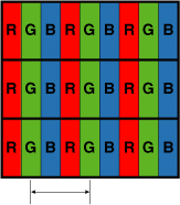
Figure 12.20 Stripe-shaped subpixels in a staggered arrangement, where pixel pitch is the distance between same color subpixel stripes.

Generally, the higher the resolution, the larger the display you will want. Why? Because operating system and application program icons and text normally use a constant number of pixels, higher display resolutions make these screen elements smaller onscreen. By using a larger display, you can use higher resolution settings and still have icons and text that are large enough to be readable. Although it is possible to change icon and text size, this often causes other problems with formatting in various windows and dialog boxes, such that in most cases it is best to stick with the default sizes.
At lower resolutions, text and onscreen icons are very large. Because the screen elements used for the Windows desktop and software menus are at a fixed pixel width and height, you’ll notice that they shrink in size onscreen as you change to the higher resolutions. You’ll be able to see more of your document or web page onscreen at the higher resolutions because each object requires less of the screen. Tables 12.16 and 12.17 show the sizes and resolutions for commonly available standard and widescreen LCD monitors.
Table 12.16 Sizes and Resolutions for Non-Widescreen (<1.50 Ratio) Monitors

Table 12.17 Sizes and Resolutions for Widescreen (>1.50 Ratio) Monitors

Because LCD monitors have a 1:1 relationship between resolution and pixels, any two displays having the same size and resolution always have the same pixel per inch or pixel pitch specification. Regardless of the actual resolution, any two displays having the same number of pixels per inch will display text, icons, and other elements on the screen at the same sizing. Although having a higher resolution display is generally considered better, you need to be careful when selecting small LCD displays with higher resolutions because icons and text will be much smaller than you might be accustomed to. You can change the icon and font sizes in Windows to compensate, but this often causes problems such as abnormal word wrapping in dialog boxes. Also, many fonts are fixed, and they will remain at the smaller size no matter what settings you change.
Depending on their ability to see and read small text, many people will have difficulty seeing the text and icons when the display is rated at 100 ppi or higher. If you are going to choose a display rated over 100 ppi, you may need to either sit closer to the screen or use bifocals or reading glasses in order to read it. Changing resolution to a lower setting is usually unsatisfactory with a flat-panel display because either the display will simply be smaller (text and icons will remain the same size, but you can’t fit as much on the screen) or the display will attempt to scale the data to fit the screen. However, scaling invariably results in a blurred and distorted image. The bottom line is that LCDs really work well only at their native resolution—something you should strongly consider when purchasing.
As a consolation, even with their tinier text and icons, LCD screens are much sharper and clearer than CRT-based monitors. So, even though the text and icons are physically smaller, they are often more readable with less eyestrain because they are sharp and perfectly focused.
CRTs don’t have a 1:1 relationship between resolution and pixels. Therefore, when you’re comparing CRTs, the smaller the pixel pitch, the sharper the images will be. As an example, the original IBM PC color monitor from the early 1980s had a pixel pitch of .43mm, whereas newer color CRTs have a pixel pitch between .25mm and .27mm, with high-end models offering .24mm or less. To avoid grainy images on a CRT, look for those with a pixel pitch of .26mm or smaller.
Horizontal and Vertical Frequency
Analog display connections such as VGA are designed to transmit signals that drive the display to draw images. These signals tell the display to draw an image by painting lines of pixels from left to right and from top to bottom. For example, if the display resolution is 1024×768, that means there are 768 lines that would be drawn, one after the other, from top to bottom. Once the 768th line is drawn, the entire image would be completed, and the process would repeat starting again from the top.
The speed at which this image drawing occurs has two components, called the horizontal frequency and the vertical frequency. These frequencies are also called scan or refresh rates. The horizontal frequency is the speed in which the horizontal lines are drawn, expressed as the total number of lines per second. The vertical frequency (or vertical refresh rate) is the speed in which complete images are drawn, expressed in the number of images per second.
Using a 1024×768 display as an example, if the vertical refresh rate is 60Hz, then all of the 768 lines that make up the image would need to be drawn 60 times per second, resulting in a horizontal frequency of 768 lines per image * 60 images per second, which equals 46,060 total lines per second, or a frequency of about 46KHz. If the vertical refresh rate were increased to 85Hz, then the horizontal frequency would be 768 * 85 = 65,280, or about 65.3KHz. The actual figures are technically a bit higher at 47.8KHz and 68.7KHz, respectively, because there is about a 5% overhead called the vertical blanking interval that was originally designed to allow the electron beam to move from the bottom back to the top of the screen without being seen. Although there is no electron beam in LCD displays, the blanking time is still used for backward compatibility as well as to send additional data that is not part of the image. The exact amount of vertical and horizontal blanking time required varies by the resolution and mode. It is governed by the VESA CVT (Coordinated Video Timings) standard.
Displays with analog connections usually have a range of scan frequencies that they can handle, which effectively controls the minimum and maximum resolutions that can be displayed. Of the vertical and horizontal frequencies, for CRT displays the vertical refresh rate is more important because it controls flicker. A refresh rate that is too low causes CRT screens to flicker, contributing to eyestrain. The higher the refresh rate you use with a CRT display, the less eyestrain and discomfort you will experience while staring at the screen.
A flicker-free refresh rate is a refresh rate high enough to prevent you from seeing any flicker. The flicker-free refresh rate varies with the size and resolution of the monitor setting (larger and higher resolutions require higher refresh rates) as well as the individual, because some people are more sensitive to it than others. In my experience, a 75Hz refresh rate is the minimum anybody should use with a CRT, especially at resolutions of 1024×768 and higher. Lower rates produce a noticeable flicker, which can cause eyestrain, fatigue, and headaches. However, although a 75Hz vertical refresh rate is sufficient for most, some people require a setting as high as 85Hz before the image is truly flicker-free. For that reason, 85Hz is considered by VESA to be the optimum refresh rate for CRT displays. Because a refresh rate that is too high can reduce video performance by making the adapter work harder to update the image more frequently, I recommend using the lowest refresh rate you are comfortable with.
Note
CRT manufacturers often used the term optimal resolution to refer to the highest resolution a given CRT monitor supports at the 85Hz VESA standard for flicker-free viewing.
Table 12.18 shows the correlation between resolution and refresh rates. As the resolution and vertical refresh rate increase, so must the horizontal frequency. The maximum horizontal frequency supported by the display is the limiting factor when selecting higher refresh rates at a given resolution.
Table 12.18 Refresh Rates Comparison
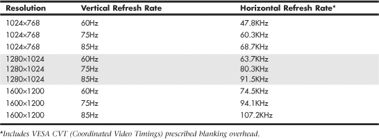
For example, let’s say you have a CRT display that supports a maximum horizontal frequency of 75KHz. That display would be capable of an 85Hz refresh rate at 1024×768, but would only be capable of a 60Hz refresh at either 1280×1024 or 1600×1200. Because the flickering on a CRT at 60Hz is unacceptable, using those resolutions would be out of the question. By comparison, a monitor capable of supporting a 110KHz horizontal frequency could handle even the highest 1600×1200 resolution at an 85Hz refresh rate, which would mean no flicker. Premium CRT displays offer flicker-free refresh rates at higher resolutions. Note that you can’t use refresh rates higher than the display can support, and in some cases with older CRTs, selecting a refresh rate in excess of the monitor’s maximum can actually cause damage to the display circuitry!
Windows supports Plug and Play (PnP) monitor configuration if both the monitor and video adapter support the Data Display Channel (DDC) feature. Using DDC communication, Windows can read the VESA Extended Display Identification Data (EDID) from the display and use it to configure the graphics controller to match the display’s capabilities, such as supported resolutions and refresh rates. This normally prevents the user from selecting refresh rates that the monitor cannot support.
LCD monitors aren’t affected by vertical refresh rates like CRTs, because LCDs avoid problems with flicker because of their design. LCDs use transistors to activate all the pixels in the image at once, as opposed to a scanning electron beam that must work its way from the top to the bottom of the screen to create an image. But most importantly, LCDs have a CCFL (cold cathode fluorescent lamp) or LED (light emitting diode) backlight that for all intents and purposes doesn’t flicker (it operates either continuously or at very high frequencies of 200Hz or more). In other words, although a vertical refresh rate setting of 60Hz is considered bad for CRTs, that is the standard rate used by most LCDs because they don’t exhibit visible flicker. Although most LCDs can accept refresh rates of up to 75Hz, in most cases selecting rates higher than 60Hz will only force the video card to work harder and won’t actually affect what you see on the display.
Tip
If you try to use a refresh rate higher than your display can support, you might see a message that you have selected an out-of-range frequency. If you use a dual-head video card, keep in mind that some models don’t permit you to assign different refresh rates to each monitor. If you have both a CRT and an LCD connected to such a video card, use the highest refresh rate supported by both displays (usually 75Hz) to minimize flicker on the CRT.
Interlaced Versus Noninterlaced
Some monitors and video adapters can support both interlaced as well as noninterlaced modes. In noninterlaced (conventional) mode, the screen is drawn from top to bottom, one line after the other, completing the screen in one pass. In interlaced mode, the screen is drawn in two passes—with the odd lines first and the even lines second. Each pass takes half the time of a full pass in noninterlaced mode.
Early high-resolution CRT monitors used interlacing to reach their maximum resolutions; as with interlacing, the vertical and horizontal scan frequencies were cut in half. Unfortunately this usually introduces noticeable flicker into the display, so in most cases interlacing should be avoided where possible. Fortunately most modern monitors support noninterlaced modes at all supported resolutions, thus avoiding the slow screen response and potential flicker caused by interlacing.
Note
The 1080i HDTV standard is an interlaced mode that is sometimes used because it requires half the bandwidth of the 1080p (progressive) mode. However, in most cases, you will not see a DLP, LCD, or plasma TV flicker when it receives a 1080i signal. That is because the signal is normally converted internally into a progressive signal and scaled to the display’s native resolution.
Image Brightness and Contrast
Although it’s a consideration that applies to both LCDs and CRTs, the brightness of a display is especially important in an LCD panel, because brightness can vary a great deal from one model to another. Brightness for LCD panels is measured in candelas per square meter (cd/m2), which is also called a nit (from the Latin nitere, “to shine”) and often abbreviated as nt. Typical ratings for good display panels are between 200 and 450 nits—the brighter the better.
Contrast is normally expressed as the ratio between white and black, with higher ratios being better. There are unfortunately different ways to make the measurement, but the one that is most important is the static contrast ratio, which is the ratio from brightest to darkest that can be produced on a display simultaneously. Many display manufacturers like to quote dynamic contrast ratios instead, because they are measured over time with different backlight brightness settings and produce significantly larger numbers. For example, a display with a 1000:1 static contrast ratio can also have an 8000:1 (or higher) dynamic contrast ratio. Even more confusion comes from the fact that many display manufacturers like to assign their own proprietary names to dynamic contrast ratios—for example, Acer calls it ACM (Adaptive Contrast Management), whereas ASUS calls it ASCR (ASUS Smart Contrast Ratio). I recommend comparing displays using only the static ratio instead.
Typical static contrast ratio values range from 400:1 to 1500:1. Anything higher than that is generally a dynamic ratio. Because of the capabilities of the human eye, static ratios over 1000:1 offer very little perceptible visual difference. A good combination of both brightness and contrast is a brightness rating of 300 nits (or more) along with a static contrast ratio of 1000:1.
Note
When you evaluate an LCD TV monitor, be sure to note the brightness settings available in computer mode and TV mode. Many of these displays provide a brighter picture in TV mode than in computer mode.
Display Power Management Signaling (DPMS)
Monitors, like virtually all power-consuming computer devices, have been designed to save energy wherever and whenever possible. Virtually all monitors sold in recent years have earned the Environmental Protection Agency’s Energy Star logo by reducing their current draw down to 15 watts (CRTs) or 5 watts (LCDs) or less when idle. Power-management features in the monitor, as well as controls provided in the system BIOS and in the latest versions of Windows, help monitors and other types of computing devices use less power.
![]() For more information about power management, see Chapter 18, “Power Supplies,” p. 913.
For more information about power management, see Chapter 18, “Power Supplies,” p. 913.
Display Power-Management Signaling (DPMS) is a VESA specification that defines the signals a computer sends to a monitor to indicate idle times. The operating system normally decides when to send these signals, depending on how you have set up the power management settings.
Table 12.19 shows the various signal states and relative power consumption according to the DPMS state selected. Normally the monitor will be placed in Suspend mode after a period of inactivity specified in the OS power management settings.
Table 12.19 Display Power Management Signaling States

Virtually all CRT monitors with power management features meet the requirements of the United States EPA’s Energy Star labeling program, which requires that monitor power usage be reduced from up to 100 watts or more (when operating normally) to 15 watts or less in standby mode. LCD monitors comply with the far more stringent Energy 2000 (E2000) standard developed in Switzerland. E2000 requires that monitors use less than 5 watts when in standby mode. Note that LCD displays generally use one-third less power than CRTs in either operating or standby mode.
LCD Technology
Because of their light weight, smaller overall size, and much greater clarity, LCD panels have replaced CRT displays in virtually all new computer installations. Desktop LCD panels use the same technology that first appeared in laptop computers. Compared to CRTs, LCDs have completely flat, thin screens and low power requirements (30 watts versus up to 100 watts or more for CRT monitors). The color quality of a good active-matrix LCD panel can exceed that of many CRT displays, particularly when viewed from head on.
How LCD Displays Work
In an LCD, polarizing filters allow only light waves that are aligned with the filter to pass through. After passing through one polarizing filter, the light waves are all aligned in the same direction.
A second polarizing filter aligned at a right angle to the first blocks all those waves. By changing the angle of the second polarizing filter, you can change the amount of light allowed to pass accordingly. It is the role of the liquid crystal cell to act as a polarizing filter that can change the angle of polarization and control the amount of light that passes. The liquid crystals are tiny rod-shaped molecules that flow like a liquid. They enable light to pass straight through, but an electrical charge alters their orientation, which subsequently alters the orientation of light passing through them.
In a color LCD, there are three cells for each pixel—one each for displaying red, green, and blue—with a corresponding transistor for each cell. The red, green, and blue cells that make up a pixel are sometimes referred to as subpixels.
Active-Matrix Displays
LCD panels use a type of active-matrix technology known as a thin-film transistor (TFT) array. TFT is a method for packaging from one (monochrome) to three (RGB color) transistors per pixel within a flexible material that is the same size and shape as the display. Thus, the transistors for each pixel lie directly behind the liquid crystal cells they control.
Two TFT manufacturing processes account for most of the active-matrix displays on the market today: hydrogenated amorphous silicon (a-Si) and low-temperature polysilicon (p-Si). These processes differ primarily in their costs. At first, most TFT displays were manufactured using the a-Si process because it required lower temperatures (less than 400°C) than the p-Si process of the time. Now, lower-temperature p-Si manufacturing processes are making this method an economically viable alternative to a-Si.
To improve horizontal viewing angles in the latest LCDs, some vendors have modified the classic TFT design. For example, Hitachi’s in-plane switching (IPS) design—also known as STFT—aligns the individual cells of the LCD parallel to the glass, running the electric current through the sides of the cells and spinning the pixels to provide more even distribution of the image to the entire panel area. Hitachi’s Super-IPS technology also rearranges the liquid crystal molecules into a zigzag pattern, rather than the typical row-column arrangement, to reduce color shift and improve color uniformity. The similar multidomain vertical alignment (MVA) technology developed by Fujitsu divides the screen into different regions and changes the angle of the regions.
Both Super-IPS and MVA provide a wider viewing angle than traditional TFT displays. Other companies have different names for the same technology—for example, Sharp calls it Ultra High Aperture (UHA). Manufacturers often like to think up their own buzzwords for the same technology because it makes their products seem different, but the results they generate are all largely the same. Because larger LCDs can exhibit shifts in viewing angle even for an individual user, these more advanced technologies are often used on larger and more expensive panels.
Benefits of LCD Panels
LCD monitors offer a number of benefits when compared to conventional CRT glass tube monitors. Because LCDs use direct addressing of the display (each pixel in the picture corresponds with a transistor), they produce a high-precision image. LCDs can’t have the common CRT display problems of pincushion or barrel distortion, nor do they experience convergence errors (halos around the edges of onscreen objects).
LCD panels are less expensive to operate than CRTs because they feature lower power consumption and much less heat buildup than CRTs. Because LCD units lack a CRT, no concerns exist about electromagnetic VLF or ELF emissions. Although LCDs offer a comparable mean time between failures (MTBF) to CRT displays, the major reason for LCD failures is the inverter or backlight, which might be relatively inexpensive to replace in some models. CRT failures usually involve the picture tube, which is the most expensive portion of the display and is often not cost-effective to replace.
LCD panels offer a significantly smaller footprint (front-to-back dimensions), and some offer optional wall or stand mounting. LCD panels also weigh substantially less than comparably sized CRTs. For example, a 17″ LCD weighs less than 10 lbs., compared to the 50 lbs. weight of 19″ CRTs with a similar viewing area.
Potential Drawbacks of LCD Panels
Although LCD monitors have almost completely replaced CRTs in new systems, there are some potential drawbacks to consider:
• High-quality LCD panels are great for displaying sharp text and graphics. But they sometimes can’t display as wide a range of very light and very dark colors as can CRTs.
• Many LCDs don’t react to changes in the images being displayed as quickly as CRTs. This can cause full-motion video, full-screen 3D games, and animation to look smeared onscreen. To avoid this problem, look for LCDs that offer a gray-to-gray response time of 5ms or faster. Some LCDs now have gray-to-gray response times under 2ms (the lower the number, the better). Note that LCD makers use various methods of measuring response time, including black to white. Gray-to-gray response times are shorter than black-to-white response times on identical hardware.
• Although recent LCD displays offer wider viewing angles (up to 170° or more horizontal and up to 120° vertical), a CRT is still superior for wide-angle viewing.
LCD Monitor Selection Criteria
When selecting an LCD monitor, I recommend taking the following criteria into consideration:
• LCD monitors work best only at their native resolution, and can vary greatly in how they scale to lower resolutions. Because higher resolutions result in smaller text and icons, make sure you don’t purchase a display with a higher resolution than you can easily see or use. LCD monitors vary greatly in how well they scale from native to alternative resolutions, so you should evaluate the panel both at its native resolution and at any other resolutions you plan to use.
• For larger displays supporting higher resolutions, using a VGA analog connection will result in a poor quality image. In that case, you will want to use a digital connection, which means that both the video adapter and display will need compatible digital connections such as DisplayPort, DVI, or HDMI.
• LCDs have slower response times than most CRTs. For good performance with games, video, and animation, look for gray-to-gray response times of 5ms or faster.
• LCD displays have lower viewing angles than CRTs. This can be an important consideration if you’re planning to use your LCD monitor for group presentations. To improve the horizontal viewing area, several manufacturers have developed patented improvements to the basic TFT display, such as Hitachi’s in-plane switching (IPS), Fujitsu’s multidomain vertical adjustment (MVA), and Mitsubishi’s feed forward driving (FFD)—most of which have been licensed to other leading LCD makers. If you need wider angle viewing capability, look for LCD displays using these technologies to achieve horizontal viewing angles of 170° or more.
• A high-contrast ratio (luminance difference between white and black) makes for sharper text and vivid colors. Look for static contrast ratios of 1000:1 or more.
• Optional features such as integrated speakers, webcams, and Universal Serial Bus (USB) hubs are available on many displays.
CRT Display Technology
Cathode-ray tube (CRT) technology is the same used in older television sets. In the last couple of years, CRTs have become scarce on store shelves, mainly due to the availability of lower cost LCDs.
CRTs consist of a vacuum tube enclosed in glass. One end of the tube contains an electron gun assembly that projects three electron beams, one each for the red, green, and blue phosphors used to create the colors you see onscreen; the other end contains a screen with a phosphorous coating.
When heated, the electron gun emits a stream of high-speed electrons that are attracted to the other end of the tube. Along the way, a focus control and deflection coil steer the beam to a specific point on the phosphorous screen. When struck by the beam, the phosphor glows. This light is what you see when you watch TV or look at your computer screen. Three layers of phosphors are used: red, green, and blue. A metal plate called a shadow mask is used to align the electron beams; it has slots or holes that divide the red, green, and blue phosphors into groups of three (one of each color).
Monitors based on Sony Trinitron or Mitsubishi DiamondTron picture tubes used an aperture grille type mask to separate red, green, and blue phosphors, resulting in strips of square pixels in a linear arrangement, similar to an LCD. NEC’s ChromaClear monitors used a variation on the aperture grille called the slotted mask, which is brighter than standard shadow-mask monitors and more mechanically stable than aperture grille–based monitors. This resulted in a staggered pixel arrangement.
Various types of shadow masks affect picture quality, and the distance between each group of three (the dot or pixel pitch) affects picture sharpness.
![]() See “Pixels,” p. 711 (this chapter).
See “Pixels,” p. 711 (this chapter).
Figure 12.21 illustrates the interior of a typical CRT.
Figure 12.21 A typical CRT monitor is a large vacuum tube. It contains three electron guns (red, green, and blue) that project the picture toward the front glass of the monitor. High voltage is used to produce the magnetism that controls the electron beams that create the picture displayed on the front of the CRT.

The phosphor chemical has a quality called persistence, which indicates how long this glow remains onscreen. Persistence is what causes a faint image to remain on your TV screen for a few seconds after you turn off the set. The vertical scanning frequency (also called the refresh rate) of the display specifies how many times per second the image is refreshed. You should have a good match between persistence and refresh rate so the image has less flicker (which occurs when the persistence is too low) and no ghost images (which occurs when the persistence is too high).
The electron beam moves very quickly, sweeping the screen from left to right in lines from top to bottom, in a pattern called a raster. The horizontal scan rate refers to the speed at which the electron beam moves laterally across the screen, measured in the number of lines drawn per second.
During its sweep, the beam strikes the phosphor wherever an image should appear onscreen. The beam also varies in intensity to produce different levels of brightness. Because the glow begins to fade almost immediately, the electron beam must continue to sweep the screen to maintain an image—a practice called redrawing or refreshing the screen.
Due to the lower persistence phosphors used in PC monitor CRTs, most have an ideal refresh rate (also called the vertical scan frequency) of 85Hz, which means the screen is refreshed 85 times per second. Refresh rates that are too low cause the screen to flicker, contributing to eyestrain.
Curved Versus Flat Picture Tubes
CRT screens come in two primary styles: curved and flat. Older CRT monitors use a curved picture tub, which bulges outward from the middle of the screen. Although this type of CRT is inexpensive to produce, the curved surface can cause distortion and glare, especially when used in a brightly lit room. Some vendors use antiglare treatments to reduce the reflectivity of the typical curved CRT surface.
The traditional screen is curved both vertically and horizontally. Some are curved only horizontally and flat vertically; these are referred to as flat square tube (FST) designs.
Emissions (CRTs)
One drawback of CRT monitors is that they produce electromagnetic fields. Several medical studies indicate that these electromagnetic emissions can cause health problems, such as miscarriages, birth defects, and cancer. The risk might be low, but if you spend a third of your day (or more) in front of a CRT monitor, that risk is increased.
The concern is that VLF (very low frequency) and ELF (extremely low frequency) emissions might affect the body. These two emissions come in two forms: electric and magnetic. Some research indicates that ELF magnetic emissions are more threatening than VLF emissions because they interact with the natural electric activity of body cells. Monitors are not the only culprits; significant ELF emissions also come from electric blankets and power lines.
Note
ELF and VLF are a form of electromagnetic radiation; they consist of radio frequencies below those used for normal radio broadcasting.
The standards shown in Table 12.20 have been established to regulate emissions and other aspects of monitor operations. Even though these standards originated with Swedish organizations, they are recognized and supported throughout the world.
Table 12.20 Monitor Emissions Standards

Today, virtually all CRT monitors on the market support TCO standards.
If you are using an older monitor that does not meet TCO standards, you can take other steps to protect yourself. The most important is to stay at arm’s length (about 28 inches) from the front of your monitor. When you move a couple of feet away, ELF magnetic emission levels usually drop to those of a typical office with fluorescent lights. Likewise, monitor emissions are weakest at the front of a monitor, so stay at least 3 feet from the sides and backs of nearby monitors.
Note that because plasma and LCD panels don’t use electron guns or magnets, they don’t produce ELF emissions.
Plasma Display Technology
Plasma displays have a long history in PCs. In the late 1980s, IBM developed a monochrome plasma screen that displayed orange text and graphics on a black background. IBM used a 10-inch version of this gas plasma display on its P70 and P75 briefcase portable systems that were originally released way back in 1988.
Unlike the early IBM monochrome plasma screens, today’s plasma displays are capable of displaying 24-bit or 32-bit color. Plasma screens produce an image by using electrically charged gas (plasma) to illuminate triads of red, green, and blue phosphors, as shown in Figure 12.22.
Figure 12.22 A cross-section of a typical plasma display.

The display and address electrodes create a grid that enables each subpixel to be individually addressed. By adjusting the differences in charge between the display and address electrodes for each triad’s subpixels, the signal source controls the picture.
Typical plasma screens range in size from 42″ to 50″ or larger. Because they are primarily designed for use with DVD, TV, or HDTV video sources, they are sized and optimized for video rather than computer use.
LCD and DLP Projectors
Originally, data projectors were intended for use in boardrooms and training facilities. However, with the rise of home theater systems, the increasing popularity of working from home, and major price reductions and improvements in projector technology, portable projectors are an increasingly popular alternative to large-screen TVs and plasma displays.
Two technologies are used in the construction of data projectors:
• Liquid crystal display (LCD)
• Digital light processing (DLP)
Instead of using triads of subpixels as in a flat-panel or portable LCD, an LCD projector works by separating white light into red, green, and blue wavelengths and directing each wavelength through a corresponding LCD panel. Each LCD panel’s pixels are opened or closed according to the signals received from the signal source (computer, DVD, or video player) and are combined into a single RGB image that is projected onto the screen. A relatively hot projection lamp must be used to project LCD images, so LCD projectors require some cool-down time before they can be stored.
The other major technology for presentation and home theater projectors uses Texas Instruments’ own digital light processing (DLP) technology. DLP projectors use a combination of a rapidly spinning color wheel and a microprocessor-controlled array of tiny mirrors known as a digital micromirror device (DMD). Each mirror in a DMD corresponds to a pixel, and the mirrors reflect light toward or away from the projector optics. Depending on how frequently the mirrors are switched on, the image varies from white (always on) to black (never on) through as many as 1,024 gray shades. The color wheel provides color data to complete the projected image. Compared to LCD projectors, DLP projectors are more compact, are lighter, and cool down more quickly after use. Although DLP projects were originally more expensive than LCD projectors, they are now about the same price. Most current projectors also support HDTV resolutions of 720p and 1080i, enabling a single projector to work as either a PC or TV display.
Figure 12.23 illustrates how a DLP-based projector produces the image.
Figure 12.23 How a typical DLP projector works.
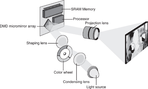
The earliest DLP projectors used a simple three-color (RGB) wheel, as shown in Figure 12.23. However, more recent models have used a four-segment (RGB and clear) or a six-segment (RGBRGB) wheel to improve picture quality.
Note
For more information about digital light processing, see the official Texas Instruments website about DLP technology at www.dlp.com.
Using Multiple Monitors
One of the most useful things you can do for increasing the usability and productivity of a PC is to attach multiple monitors. Adding additional monitors gives you more screen real-estate to use for running multiple applications simultaneously. When you configure a system to use multiple monitors, the operating system creates a virtual desktop—that is, a display that exists in video memory that combines the total screen real-estate of all of the attached displays. You use the multiple monitors to display various portions of the virtual desktop, enabling you to place the open windows for different applications on separate monitors and move them around at will.
Although having three or more displays is entirely possible, just adding a second monitor can be a boon to computing productivity. For example, you can leave an email client or word processor maximized on one monitor and use the other monitor for web browsing, research documents, and more.
Using multiple monitors requires an independent video signal for each display. This can be provided by one of the following methods:
• Dualview—A single graphics adapter with two video outputs, also known as a dual-head graphics adapter.
• Homogeneous adapters—Two or more graphics adapters that use the same driver.
• Heterogeneous adapters—Two or more graphics adapters that use different drivers.
When multiple video adapters are installed, the system will identify one of the video adapters as primary. The primary adapter is sometimes called the VGA adapter and is the one that will display the POST (Power-On Self Test) and BIOS Setup screens. This is a function of the motherboard and motherboard BIOS. Most modern BIOSs allow you to choose the primary display adapter via a setting in the BIOS Setup. Normally the options are onboard (built in), PCI, or PCIe (PCI Express). For the PCI and PCIe selections, if you have multiple adapters installed, the primary will be the one in the highest priority slot.
If the BIOS does not let you select which device should be the primary display, it decides solely based on the priority of the buses and/or slots in the machine. Depending on the BIOS used by your system, you might need to check in various places for the option to select the primary display adapter; however, in most cases it will be in the Video Configuration menu.
Dualview
Most older video cards have only a single output; however, many newer video cards now have dual outputs. With the exception of laptops, the same is true for most motherboard-based video adapters. Laptops have almost always had dualview graphics adapters, whereas most desktop motherboards have not until recently.
A dualview card is preferable to using two separate cards because only one slot is used, as are fewer system resources and even power. The types of video outputs on dual-head cards can vary, so make sure you choose a card that has the outputs you need or that the existing outputs can be changed via adapters. Digital outputs such as DVI and DisplayPort are preferred because these can normally be converted to others with inexpensive adapters.
Microsoft states that only Windows XP and later support dualview operation by default; however, with the proper driver support, you can use dualview adapters in Windows 98/Me and 2000. If you are using an older OS and don’t see an option to extend the desktop onto the second display, try updating the driver to the latest version.
Homogeneous Adapters
The best solution for running multiple graphics adapters in a single system is to ensure they are homogeneous. This means that they use the same driver, which implies that they must also have chipsets from the same manufacturer (such as ATI or NVIDIA) and from compatible families within that chipset manufacturer. Using multiple homogeneous adapters is supported in Windows 98/Me (up to nine total displays) and in Windows 2000 and later (up to 10 displays) using any combination of single- or dualview adapters. The installation is simple because only a single driver is required for all the adapters and displays.
Because ATI and NVIDIA use a unified driver architecture to support their current product lines, you can use two (or more) ATI-based or NVIDIA-based cards to create the desired homogeneous multiple-monitor configuration. The specific cards and even chipsets can be different, as long as they can use the same driver.
Heterogeneous Adapters
Heterogeneous adapters are those using chipsets from different manufacturers or from incompatible chipset families within the same manufacturer, which therefore require different drivers.
Heterogeneous adapters are supported in Windows 98 through Windows XP and Windows 7 and later, but are not supported in Windows Vista. That is because with Windows Vista, Microsoft introduced a new graphics driver model called WDDM (Windows Display Driver Model) 1.0, and WDDM 1.0 drivers only support homogeneous adapters (that is, multiple graphics adapters that use the same driver). This means, for example, that you cannot use an ATI and an NVIDIA GPU in the same system (or any other combination of GPUs that use different drivers) when WDDM 1.0 drivers are used. With Windows 7, Microsoft introduced WDDM 1.1, which includes support for heterogeneous adapters along with many other improvements.
Note
Heterogeneous adapters can be used under Vista if you install Windows XPDM (XP Driver Model) drivers instead of WDDM (Windows Display Driver Model) 1.0 drivers. However, installing XPDM drivers in Vista disables support for DirectX 10 and the Aero graphical interface. In addition, if you attempt to run both XPDM and WDDM drivers in the same system, you will see an “Incompatible display adapter has been disabled” error message, and the secondary adapter will be disabled. For more information about multiple monitor support and limitations in Windows Vista, see www.microsoft.com/whdc/device/display/multimonVista.mspx.
Video Capture Devices
Actually capturing and recording video from external sources and saving the files onto your PC requires a video capture device called a capture card, TV tuner, video digitizer, or video grabber.
Note
In this context, the technical nomenclature again becomes confusing because the term video here has its usual connotation; that is, it refers to the display of full-motion photography on the PC monitor. When evaluating video hardware, be sure to distinguish between devices that capture still images from a video source and those that capture full-motion video streams.
Today, video sources come in two forms:
• Analog
• Digital
Analog video can be captured from traditional sources such as broadcast or cable TV, VCRs, and camcorders using VHS or similar tape standards. This process is much more demanding of storage space and system performance than still images are.
The typical computer screen was designed to display mainly static images. The storing and retrieving of these images requires managing huge files. Consider this: A single, full-screen color image in an uncompressed format can require as much as 2MB of disk space; a 1-second video would therefore require 45MB. Likewise, any video transmission you want to capture for use on your PC must be converted from an analog NTSC signal to a digital signal your computer can use. On top of that, the video signal must be moved inside your computer at 10 times the speed of the conventional ISA bus structure. You need not only a superior video card and monitor, but also an excellent expansion bus, such as PCI Express or AGP.
Considering that full-motion video can consume massive quantities of disk space, it becomes apparent that data compression is all but essential. Compression and decompression apply to both video and audio. Not only does a compressed file take up less space, it also performs better simply because less data must be processed. When you are ready to replay the video/audio, the application decompresses the file during playback. In any case, if you are going to work with video, be sure that your hard drive is large enough and fast enough to handle the huge files that can result.
Compression/decompression programs and devices are called codecs. Two types of codecs exist: hardware-dependent codecs and software (or hardware-independent) codecs. Hardware codecs typically perform better; however, they require additional hardware—either an add-on card or a high-end video card with hardware codecs built in. Software codecs do not require hardware for compression or playback, but they typically do not deliver the same quality or compression ratio. Following are two of the major codec algorithms:
• JPEG (Joint Photographic Experts Group)—Originally developed for still images, JPEG can compress and decompress at rates acceptable for nearly full-motion video (30 fps). JPEG still uses a series of still images, which makes editing easier. JPEG is typically lossy (meaning that a small amount of the data is lost during the compression process, slightly diminishing the quality of the image), but it can also be lossless. JPEG compression functions by eliminating redundant data for each individual image (intraframe). Compression efficiency is approximately 30:1 (20:1–40:1).
• MPEG (Motion Picture Experts Group)—MPEG by itself compresses video at approximately a 30:1 ratio, but with precompression through oversampling, the ratio can climb to 100:1 and higher, while retaining high quality. Thus, MPEG compression results in better, faster videos that require less storage space. MPEG is an interframe compressor. Because MPEG stores only incremental changes, it is not used during editing phases.
If you will be capturing or compressing video on your computer, you’ll need software based on standards such as Microsoft’s DirectShow (the successor to Video for Windows and ActiveMovie), Windows Vista and Microsoft Media Foundation, Real Network’s Real Producer series, or Apple’s QuickTime Pro. Players for files produced with these technologies can be downloaded free from the vendors’ websites.
To play or record analog video on your multimedia PC (MPC), you need some extra hardware and software:
• Video system software, such as Microsoft’s Windows Media Player or Apple’s QuickTime for Windows.
• A compression/digitization video adapter that enables you to digitize and play large video files. When you record an animation file, you can save it in a variety of file formats such as AVI (Audio Video Interleave), MPG (MPEG format), and MOV (Apple QuickTime) format.
• A TV-out or video-out adapter, which connects your system to a VCR, disc player, or standard TV.
Depending on the video capture product you use, you have several choices for capturing analog video. The best option is to use component video. Component video uses three RCA-type jacks to carry the luminance (Y) and two chrominance (PR and PB) signals; this type of connector commonly is found on DVD players and high-end conventional and HDTV television sets. However, most home-market video capture devices usually don’t support component video.
The next best choice, and one that is supported by many home-market video capture devices, is the S-video (S-VHS) connector. This cable transmits separate signals for color (chroma) and brightness (luma). Otherwise, you must use composite video, which mixes luma and chroma. This results in a lower-quality signal, and the better your signal, the better your video quality will be.
For capturing TV signals, use a TV tuner with DVR (digital video recorder) capabilities. These devices plug into a USB port, PCI, or PCI-Express card slot and contain one or more TV tuners. Some TV tuners include DVR software that enables you to record live TV to your hard disk and pause a broadcast, or you can use the built-in DVR features in Windows Media Center. If you want to use the DVR, look for devices that include (or support) a remote control and include access to a TV program guide.
Current digital TV (DTV) requires TV tuners that support ATSC (Advanced Television Systems Committee) digital signals, which includes both standard and HDTV signals. Devices that support Clear QAM permit recording of unencrypted cable HDTV signals, and some also support CableCARD devices used by many cable TV providers for reception of premium HDTV content.
Note
Most older TV tuners only support analog reception, which has been suspended in most markets. Make sure any tuner you purchase supports DTV (digital TV), also known as ATSC (Advanced Television Systems Committee) digital television.
TV tuners that provide Windows drivers can be used by the Windows Media Center feature for live TV recording, pausing, and playback on the PC and other devices throughout the home. Some TV tuner devices can also capture S-video and composite video signals, enabling you to use a single device to capture video from TV and from VCRs or analog camcorders.
Figure 12.24 shows a typical PCI-Express TV tuner and video capture card: the ATI TV Wonder 650 PCI-Express from AMD. This example features a PCI-Express x1 interface, but other TV tuner cards use the PCI interface.
Figure 12.24 ATI’s TV Wonder 650 PCI-Express plugs into a PCI-Express x1 slot and provides analog TV, FM radio, S-video, composite video, stereo audio, and HDTV inputs. A multihead AV input cable and remote control are also included. (Photo courtesy of Advanced Micro Devices.)
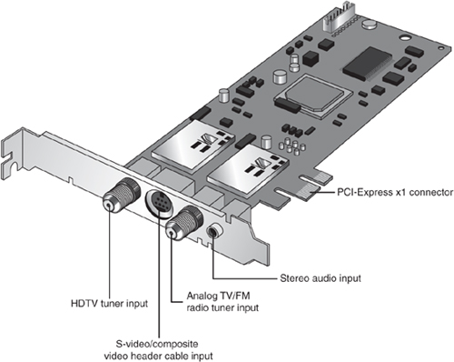
Different types of video capture devices have advantages and potential disadvantages. Table 12.21 provides a summary that will help you decide which solution is best for you.
Table 12.21 Video Capture Device Comparison

Video Troubleshooting and Maintenance
Solving most graphics adapter and monitor problems is fairly simple, but costly, because replacing the adapter or display is the normal procedure. Except for specialized CAD or graphics workstation-oriented adapters, virtually all of today’s adapters cost more to service than to replace, and the documentation required to service the hardware properly is not always available. You usually can’t get schematic diagrams, parts lists, wiring diagrams, and other documents for most adapters or monitors. However, before you take this step, be sure you have exhausted all your other options.
Remember also that many of the problems you might encounter with modern video adapters and displays are related to the drivers that control these devices rather than to the hardware. Be sure you have the latest and proper drivers before you attempt to have the hardware repaired; a solution might already be available.
Troubleshooting Video Cards and Drivers
Problem
The display works when booting and in the BIOS Setup, but not in Windows.
Solution
If you have an acceptable picture while booting or when in the BIOS Setup, but no picture in Windows, most likely you have an incorrect or corrupted video driver installed. Boot Windows in either Safe Mode (which uses the Microsoft supplied vga.sys driver) or Enable VGA Mode (which uses the current driver with VGA resolution settings). If Safe Mode or VGA Mode works, get a correct or updated driver for the video card and reinstall.
If you have overclocked your card with a manufacturer-supplied or third-party utility, you might have set the speed too high. Restart the system in Safe Mode and reset the card to run at its default speed. If you have adjusted the speed of AGP/PCI/PCI-Express slots in the BIOS Setup program, restart the system, start the BIOS Setup program, and reset these slots to run at the normal speed.
Problem
Can’t select desired color depth and resolution combination.
Solution
Verify that the card is properly identified in Windows and that the card’s memory is working properly. Use diagnostic software provided by the video card or chipset maker to test the card’s memory. If the hardware is working properly, check for new drivers. Use the vendor’s drivers rather than the ones provided with Windows.
Problem
Can’t select desired refresh rate.
Solution
Verify that the video adapter and the monitor have the latest drivers installed and are properly identified in Windows. If necessary, obtain and install updated drivers for the adapter and display.
Problem
Can’t adjust OpenGL or Direct3D (DirectX) settings.
Solution
Install the graphic card or chipset vendor’s latest drivers instead of using the drivers included with Microsoft Windows. Standard Microsoft drivers often don’t include 3D or other advanced dialog boxes.
Problem
Can’t enable multiple monitors.
Solution
If you are using a multihead graphics card, make sure the additional monitors have been enabled in the manufacturer’s driver. This might require you to open the Advanced settings for your driver (make sure you are using the latest one). If you are using two video cards in an SLI (NVIDIA) or CrossFire (ATI) configuration, you must normally disable SLI or CrossFire before you can enable additional monitors. If you are using multiple video cards in separate slots, check the BIOS Setup configuration for the primary adapter.
Problem
Can’t enable SLI operation.
Solution
Make sure the MIO (SLI bridge) device is properly installed between your video cards (refer to Figure 12.16). If you are not using identical video cards, you must use NVIDIA ForceWare v81.85 or new drivers to enable SLI operation. Make sure both cards use the same GPU family. Make sure SLI operation is enabled in the ForceWare driver.
Can’t enable CrossFire operation.
Solution
Make sure you have paired up a CrossFire Edition and standard Radeon card from the same GPU family. Also, make sure you have properly connected the CrossFire Edition and standard card to each other.
If you use later-model cards that use a CrossFire bridge interconnect, make sure the interconnect is properly attached to both cards. Make sure you are using pairs of cards with the same GPU.
Update the ATI CATALYST display drivers to the latest production version. Be sure you have enabled CrossFire in your display driver.
Problem
Can’t enable Aero 3D desktop in Windows.
Solution
Make sure your video card or integrated video is running a WDDM (Windows driver display model) driver and supports DirectX 9.0 or later. Update the driver if the hardware can support Aero. Update the card if the card does not have WDDM drivers available.
Video Drivers
Drivers are an essential, and often problematic, element of a video display subsystem. The driver enables your software to communicate with the video adapter. You can have a video adapter with the fastest processor and the most efficient memory on the market but still have poor video performance because of a badly written driver.
Video drivers generally are designed to support the processor on the video adapter. All video adapters come equipped with drivers the card manufacturer supplies, but often you can use a driver the chipset maker created as well. Sometimes you might find that one of the two provides better performance than the other or resolves a particular problem you are experiencing.
Most manufacturers of video adapters and chipsets maintain websites from which you can obtain the latest drivers; drivers for chipset-integrated video are supplied by the system, motherboard, or chipset vendor. A driver from the chipset manufacturer can be a useful alternative, but you should always try the adapter manufacturer’s driver first. Before purchasing a video adapter, you should check out the manufacturer’s site and see whether you can determine how up to date the available drivers are. At one time, frequent driver revisions were thought to indicate problems with the hardware, but the greater complexity of today’s systems means that driver revisions are a necessity. Even if you are installing a brand-new model of a video adapter, be sure to check for updated drivers on the manufacturer’s website for best results.
Note
Although most devices work best with the newest drivers, video cards can be a notable exception. Both NVIDIA and ATI now use unified driver designs, creating a single driver installation that can be used across a wide range of graphics chips. However, in some cases, older versions of drivers sometimes work better with older chipsets than the newest drivers do. If you find that system performance or stability, especially in 3D gaming, drops when you upgrade to the newest driver for your 3D graphics card, revert to the older driver.
The video driver also provides the interface you can use to configure the display your adapter produces. The driver controls the options that are available for these settings, so you can’t choose parameters the hardware doesn’t support. For example, you cannot select resolutions not supported by your display, even though your video card might support them.
In most cases, another tab called Color Management is also available. You can select a color profile for your monitor to enable more accurate color matching for use with graphics programs and printers.
Video cards with advanced 3D acceleration features often have additional properties; these are discussed later in this chapter.
Maintaining Monitors
Because a good monitor can be used for several years on more than one computer, proper care is essential to extend its life to the fullest extent.
Use the following guidelines for proper care of your monitor:
• Although phosphor burn (where an image left onscreen eventually leaves a permanent shadow) is possible on CRT or plasma displays, LCDs are immune from this problem. To prevent burn-in on non-LCD displays, use the power management settings in your operating system to blank the display after a period of inactivity. Screen savers used to be used for display protection, but they should be avoided in lieu of putting the display into Standby mode instead.
• To prevent premature failure of the monitor’s power supply, use the power-management features of the operating system to put the monitor into a low-power standby mode after a reasonable period of inactivity. Using the power-management feature is far better than using the on/off switch when you are away from the computer for brief periods. Turn off the monitor only at the end of your computing “day.”
How can you tell whether the monitor is really off or in standby mode? Look at the power LCD on the front of the monitor. A monitor that’s in standby mode usually has a blinking green or solid amber LCD in place of the solid green LCD displayed when it’s running in normal mode.
If the monitor will not go into standby mode when the PC isn’t sending signals to it, make sure the monitor is properly defined in the Display properties sheet in Windows. In addition, the Energy Star check box should be selected for any monitor that supports power management, unless the monitor should be left on at all times (such as when used in a retail kiosk or self-standing display).
• Make sure the monitor has adequate ventilation along the sides, rear, and top. Because monitors use passive cooling, a lack of adequate airflow caused by piling keyboards, folders, books, or other office debris on top of the monitor will cause it to overheat and considerably shorten its life. If you need to use a monitor in an area with poor airflow, use an LCD panel instead of a CRT because LCDs run much cooler than CRTs.
• The monitor screen and case should be kept clean. Turn off the power, spray a cleaner such as Endust for Electronics onto a soft cloth (never directly onto the monitor!), and wipe the screen and the case gently.
• If your CRT monitor has a degaussing button or feature, use it periodically to remove stray magnetic signals. Keep in mind that CRTs have powerful magnets around the picture tube, so keep magnetic media away from them.
Testing Monitors
Unlike most of the other peripherals you can connect to your computer, you can’t really tell whether a monitor suits you by examining its technical specifications. Price might not be a reliable indicator either. Testing monitors is a highly subjective process, and it is best to “kick the tires” of a few at a dealer showroom or in the privacy of your home or office (if the dealer has a liberal return policy).
Testing should also not be simply a matter of looking at whatever happens to be displayed on the monitor at the time. Many computer stores display movies, scenic photos, or other flashy graphics that are all but useless for a serious evaluation and comparison. If possible, you should look at the same images on each monitor you try and compare the manner in which they perform a specific series of tasks.
Before running the tests listed here, set your display to the highest resolution and refresh rate allowed by your combination of display and graphics card:
• Draw a perfect circle with a graphics program. If the displayed result is an oval, not a circle, this monitor will not serve you well with graphics or design software.
• Using a word processor, type some words in 8- or 10-point type (1 point equals 1/72″). If the words are fuzzy or the black characters are fringed with color, select another monitor.
• Display a screen with as much white space as possible and look for areas of color variance. This can indicate a problem with only that individual unit or its location, but if you see it on more than one monitor of the same make, it might indicate a manufacturing problem; it could also indicate problems with the signal coming from the graphics card. Move the monitor to another system equipped with a different graphics card model and retry this test to see for certain whether it’s the monitor or the video card.
• Display the Microsoft Windows desktop to check for uniform focus (with CRT displays) and brightness (with CRT and LCD displays). Are the corner icons as sharp as the rest of the screen? Are the lines in the title bar curved or wavy? Monitors usually are sharply focused at the center, but seriously blurred corners indicate a poor design. Bowed lines on a CRT can be the result of a poor video adapter or incorrect configuration of the monitor’s digital picture controls. Before you decide to replace the monitor, you should first adjust the digital picture controls to improve the display. Next, try attaching the monitor to another display adapter. If the display quality does not improve, replace the monitor.
Adjust the brightness up and down to see whether the image blooms or swells, which indicates the monitor is likely to lose focus at high brightness levels. You can also use diagnostics that come with the graphics card or third-party system diagnostics programs to perform these tests.
• With LCD panels in particular, change to a lower resolution from the panel’s native resolution using the Microsoft Windows Display properties settings. Because LCD panels have only one native resolution, the display must use scaling to handle other resolutions full-screen. If you are a web designer, are a gamer, or must capture screens at a particular resolution, this test will show you whether the LCD panel produces acceptable display quality at resolutions other than normal. You can also use this test on a CRT, but CRTs, unlike LCD panels, are designed to handle a wide variety of resolutions.
• A good CRT monitor is calibrated so that rays of red, green, and blue light hit their targets (individual phosphor dots) precisely. If they don’t, you have bad convergence. This is apparent when edges of lines appear to illuminate with a specific color. If you have good convergence, the colors are crisp, clear, and true, provided there isn’t a predominant tint in the phosphor.
• If the monitor has built-in diagnostics (a recommended feature), try them as well to test the display independently of the graphics card and system to which it’s attached. A display with built-in diagnostics shows text or a test pattern onscreen if it is receiving power when the host system is turned off or if the monitor is not connected to a host system.
Adjusting Monitors
One embarrassingly obvious fix to monitor display problems that is often overlooked by many users is to adjust the controls on the monitor, such as contrast and brightness. Although most recent monitors use front-mounted controls with onscreen display (OSD), other adjustments might also be possible.
Older CRT monitors, for example, may have a focus adjustment screw on the rear or side of the unit. Because the adjusting screw is deep inside the case, the only evidence of its existence is a hole in the plastic grillwork. To adjust the monitor’s focus, you must stick a long-shanked insulated screwdriver about 2″ into the hole and feel around for the screw head. This type of adjustment can save you an expensive repair bill. Always examine the monitor case, documentation, and manufacturer’s website or other online services for the locations of adjustment controls.
Virtually all recent monitors use digital controls instead of analog controls. This has nothing to do with the signals the monitor receives from the computer, but only the controls (or lack of them) on the front panel that enable you to adjust the display. Monitors with digital controls have a built-in menu system that enables you to set parameters such as brightness (which adjusts the black level of the display), contrast (which adjusts the luminance of the display), screen size, vertical and horizontal shifts, color, phase, and focus. A button brings the menu up onscreen, and you use controls to make menu selections and vary the settings. When you complete your adjustments, the monitor saves the settings in nonvolatile RAM (NVRAM) located inside the monitor. This type of memory provides permanent storage for the settings with no battery or other power source. You can unplug the monitor without losing your settings, and you can alter them at any time in the future. Digital controls provide a much higher level of control over the monitor and are highly recommended.
Digital controls make adjusting CRT monitors suffering from any of the geometry errors shown in Figure 12.25 easy. Before making these adjustments, be sure the vertical and horizontal size and position are correct.
Figure 12.25 Typical geometry errors in CRT monitors; these can be corrected on most models that have digital picture controls.
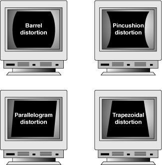
Although LCD panels aren’t affected by geometry errors as CRT monitors can be, they can have their own set of image-quality problems, especially if they use the 15-pin analog VGA video connector. Pixel jitter and pixel swim (in which adjacent pixels turn on and off) are relatively common problems that occur when you are using an LCD monitor connected to your PC with an analog VGA connector.
The Auto-Tune option available in many LCD panels’ OSDs can be used to fix these and other LCD display problems.
Bad Pixels
A so-called bad pixel is one in which the red, green, or blue subpixel cell remains permanently on or off. Those that are permanently on are often called stuck pixels, whereas those that are permanently off are called dead pixels. Failures in the on state seem to be more common. In particular, pixels stuck on are very noticeable on a dark background as tiny red, green, or blue dots. Although even one of these can be distracting, manufacturers vary in their warranty policies regarding how many bad pixels are required before you can get a replacement display. Some vendors look at both the total number of bad pixels and their locations. Fortunately, improvements in manufacturing quality make it less and less likely that you will see LCD screens with bad pixels.
Although there is no standard way to repair bad pixels, a couple of simple fixes might help. One involves tapping or rubbing on the screen. For example, I have actually repaired stuck pixels on several occasions by tapping with my index finger on the screen directly over the pixel location (with the screen powered on). Because I find a constantly lit pixel to be more irritating than one that is constantly dark, this fix has saved me a lot of aggravation (when it has worked). A similar technique is to use the tip of a PDA stylus or ballpoint pen to apply pressure or to tap directly on the stuck pixel. I recommend you wrap a damp cloth over the tip to prevent scratching the screen. Some have had success by merely rubbing the area where the stuck or dead pixel is located.
Another potential fix involves using software to rapidly cycle the stuck pixel (as well as some adjacent ones), which sometimes causes the stuck pixel to become unstuck and function properly. The two main programs for doing this are Udpixel (http://udpix.free.fr) and Jscreenfix (www.jscreenfix.com).
Unfortunately, none of these fixes work all the time; in fact, in most cases the pixel will likely remain stuck on or dead no matter what you try. If you have stuck or dead pixels that do not respond to any of the fixes I’ve detailed, you might want to contact the screen or laptop manufacturer to inquire about its bad pixel replacement policy. Since the policies can vary widely among different manufacturers and displays, to find the allowable defect limits for your specific display, I recommend you consult the documentation or contact the manufacturer directly.
Troubleshooting Monitors
Problem
No picture.
Solution
If the LED on the front of the monitor is yellow or flashing green, the monitor is in power-saving mode. Move the mouse or press Alt+Tab on the keyboard and wait up to 1 minute to wake up the system if the system is turned on.
If the LED on the front of the monitor is green, the monitor is in normal mode (receiving a signal), but the brightness and contrast are set incorrectly; adjust them.
If no lights are lit on the monitor, check the power and power switch. Check the surge protector or power director to ensure that power is going to the monitor. Replace the power cord with a known-working spare if necessary. Retest. Replace the monitor with a known-working spare to ensure that the monitor is the problem.
Check data cables at the monitor and video card end.
Problem
Jittery picture quality.
Solution
For LCD monitors, use display-adjustment software or onscreen menus to reduce or eliminate pixel jitter and pixel swim caused by running the digital LCD display with an analog (VGA) video source. Use a digital connection (DVI, HDMI, or DisplayPort) instead of the VGA connection to avoid digital-analog-digital conversion problems like these.
For all monitors, check cables for tightness at the video card and the monitor (if removable):
• Remove the extender cable and retest with the monitor plugged directly into the video card. If the extender cable is bad, replace it.
• Check the cables for damage; replace as needed.
• If problems are intermittent, check for interference. (Microwave ovens near monitors can cause severe picture distortion when turned on.)
For CRT monitors, check refresh-rate settings; reduce them until acceptable picture quality is achieved:
• Use onscreen picture adjustments until an acceptable picture quality is achieved.
• If problems are intermittent and can be “fixed” by waiting or gently tapping the side of the monitor, the monitor power supply is probably bad or has loose connections internally. Service or replace the monitor.
Repairing Monitors
Although a display often is replaced as a whole unit, some larger displays might be cheaper to repair than to replace. If you decide to repair the monitor, your best bet is to either contact the company from which you purchased the display or contact one of the companies that specialize in monitor depot repair.
Depot repair means you send in your display to repair specialists who either fix your particular unit or return an identical unit they have already repaired. This usually is accomplished for a flat-rate fee; in other words, the price is the same no matter what they have done to repair your actual unit.
Because you usually get a different (but identical) unit in return, they can ship out your repaired display immediately upon receiving the one you sent in, or even in advance in some cases. This way, you have the least amount of downtime and can receive the repaired display as quickly as possible. In some cases, if your particular monitor is unique or one they don’t have in stock, you must wait while they repair your specific unit.
Troubleshooting a failed monitor is relatively simple. If your display goes out, for example, a swap with another monitor can confirm that the display is the problem. If the problem disappears when you change the display, the problem is almost certainly in the original display or the cable; if the problem remains, it is likely in the video adapter or PC itself.
Many of the better quality, late-model monitors have built-in self-diagnostic circuitry. Check your monitor’s manual for details. Using this feature, if available, can help you determine whether the problem is really in the monitor, in a cable, or somewhere else in the system. If self-diagnostics produce an image onscreen, look to other parts of the video subsystem for your problem.
The monitor cable can sometimes be the source of display problems. A bent pin in the connector that plugs into the video adapter can prevent the monitor from displaying images, or it can cause color shifts. Most of the time, you can repair the connector by carefully straightening the bent pin with sharp-nosed pliers. A loose cable can also cause color shifts; make sure the cable is securely attached.
If the pin breaks off or the connector is otherwise damaged, you can sometimes replace the monitor cable. Some monitor manufacturers use cables that disconnect from the monitor and video adapter, whereas others are permanently connected. Depending on the type of connector the device uses at the monitor end, you might have to contact the manufacturer for a replacement.
If you narrow down the problem to the display, consult the documentation that came with the monitor or call the manufacturer for the location of the nearest factory repair depot. Third-party depot repair service companies are also available that can repair most displays (if they are no longer covered by a warranty); their prices often are much lower than factory service.
Caution
You should never attempt to repair a CRT monitor yourself. Touching the wrong component can be fatal. The display circuits can hold extremely high voltages for hours, days, or even weeks after the power is shut off. A qualified service person should discharge the cathode-ray tube and power capacitors before proceeding.