
Chapter 7. The ATA/IDE Interface
An Overview of the IDE Interface
The interface used to connect hard disk and optical drives to a modern PC is typically called IDE (Integrated Drive Electronics); however, I always like to point out that the official name of this interface is ATA (AT Attachment). The ATA designation refers to the fact that this interface was originally designed to connect a combined drive and controller directly to the 16-bit bus found in the 1984 vintage IBM AT (Advanced Technology) and compatible computers. The AT bus is otherwise known as the ISA (Industry Standard Architecture) bus. Although ATA is the official name of the interface, IDE is a marketing term originated by some of the 0 manufacturers to describe the drive/controller combination used in drives with the ATA interface. Integrated Drive Electronics refers to the fact that the interface electronics or controller is built into the drive and is not a separate board, as with earlier drive interfaces. Although the correct name for the particular IDE interface we most commonly use is technically ATA, many persist in using the IDE designation today. If you are being picky, you could say that IDE refers generically to any drive interface in which the controller is built into the drive, whereas ATA refers to the specific implementation of IDE that is used in most PCs.
ATA was originally a 16-bit parallel interface, meaning that 16 bits are transmitted simultaneously down the interface cable. A newer interface, called Serial ATA, was officially introduced in late 2000 and was adopted in desktop systems starting in 2003 and in laptops starting in late 2005. Serial ATA (SATA) sends 1 bit down the cable at a time, enabling thinner and smaller cables to be used, as well as providing higher performance due to the higher cycling speeds it enables. Although SATA is a completely different physical interface design, it is also backward compatible on the software level with Parallel ATA. Throughout this book, ATA refers to either just the parallel version or both the parallel and serial versions, whereas Parallel ATA (PATA) refers specifically to the parallel version and Serial ATA (SATA) refers specifically to the serial version.
Precursors to IDE
Several types of hard disk interfaces have been used for PC hard disks over the years, as shown in Table 7.1. As time has passed, the number of choices has increased; however, many of the older interface standards are obsolete and no longer viable in newer systems.
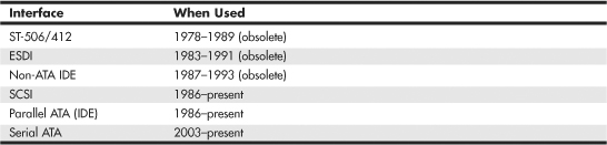
Of these interfaces, only ST-506/412 and ESDI are what you could call true disk-controller-to-drive interfaces, and they are obsolete. Non-ATA versions of IDE were used primarily in the IBM PS/2 systems and are also obsolete. Current SCSI, ATA, and Serial ATA are system-level interfaces that usually internally incorporate a chipset-based controller interface. For example, many SCSI, Parallel ATA, and Serial ATA drives incorporate the same basic controller circuitry inside the actual drive. The SCSI interface then adds another layer that connects between the drive controller and the PCI (or ISA) bus, whereas PATA and Serial ATA have a more direct connection from the controller to the AT bus attachment interface. Despite their differences, we call a SCSI, Parallel ATA (PATA), or Serial ATA (SATA) card a host interface adapter instead of a controller card because the actual controllers are inside the drives. Virtually all modern disk drives use Parallel ATA, Serial ATA, or SCSI interfaces to connect to a system.
IDE Origins
Any drive with an integrated controller could be called an IDE drive, although normally when we say IDE, we really mean the specific version of IDE called ATA. No matter what you call it, combining the drive and controller greatly simplifies installation because no separate power or signal cables run from the controller to the drive. Also, when the controller and drive are assembled as a unit, the number of total components is reduced, signal paths are shorter, and the electrical connections are more noise-resistant. This results in a more reliable and less expensive design than is possible when a separate controller, connected to the drive by cables, is used.
Placing the controller, including the digital-to-analog encoder/decoder (endec), on the drive offers an inherent reliability advantage over interfaces with separate controllers such as ST506 and ESDI. Reliability is increased because the data encoding, from digital to analog, is performed directly on the drive in a tight noise-free environment. The timing-sensitive analog information does not have to travel along crude ribbon cables that are likely to pick up noise and insert propagation delays into the signals. The integrated configuration enables increases in the clock rate of the encoder and the storage density of the drive.
Integrating the controller and drive also frees the controller and drive engineers from having to adhere to the strict guidelines imposed by the earlier interface standards. Engineers can design what essentially are custom drive and controller implementations because no other controller will ever have to be connected to the drive. The resulting drive and controller combinations can offer higher performance than earlier standalone controller and drive setups. IDE drives sometimes are called drives with embedded controllers.
The earliest IDE drives were called hardcards and were nothing more than hard disks and controllers bolted directly together and plugged into a slot as a single unit. Companies such as the Plus Development Division of Quantum took small 3 1/2″ drives (either ST-506/412 or ESDI) and attached them directly to a standard controller. The drive/controller assembly then was plugged into an ISA bus slot as though it were a normal disk controller card. Unfortunately, the mounting of a heavy, vibrating hard disk in an expansion slot with nothing but a single screw to hold it in place left a lot to be desired—not to mention the physical interference with adjacent cards, because many of these units were much thicker than a controller card alone.
Several companies got the idea to redesign the controller to replace the logic board assembly on a standard hard disk and then mount it in a standard drive bay just like any other drive. Because the built-in controller in these drives still needed to plug directly into the expansion bus just like any other controller, a cable was run between the drive and one of the slots. This is the origin of IDE.
Origins of ATA
Control Data Corporation (CDC; its disk drive division was later called Imprimis), Western Digital, and Compaq actually created what could be called the first ATA IDE interface drive and were the first to establish the 40-pin ATA connector pinout. The first ATA IDE drive was a 5 1/4″ half-height CDC Wren II 40MB drive with an integrated WD controller and was initially used in the first Compaq 386 systems in 1986. I remember seeing this drive for the first time in 1986 at the fall Comdex show, and besides the (at the time) unique 40-pin ribbon cable, I remember being surprised by the green activity LED on the front bezel (most drives up until then used red LEDs).
Compaq was the first to incorporate a special bus adapter in its system to adapt the 98-pin AT-bus (also known as ISA) edge connector on the motherboard to a smaller 40-pin, header-style connector into which the drive would plug. The 40-pin connector was all that was necessary because it was known that a disk controller never would need more than 40 of the ISA bus lines. Smaller 2 1/2″ ATA drives found in notebook computers use a superset 44-pin or 50-pin connection, which includes additional pins for power and configuration. The pins from the original ISA bus used in ATA are the only signal pins required by a standard-type AT hard disk controller. For example, because a primary AT-style disk controller uses only interrupt request (IRQ) line 14, the primary motherboard ATA connector supplies only that IRQ line; no other IRQ lines are necessary. Even if your ATA interface is integrated within the motherboard chipset South Bridge or I/O Controller Hub chip (as it would be in newer systems) and runs at higher bus speeds, the pinout and functions of the pins are still the same as the original design taken right off the ISA bus.
![]() See “Motherboard Connectors,” p. 259 (Chapter 4, “Motherboards and Buses”).
See “Motherboard Connectors,” p. 259 (Chapter 4, “Motherboards and Buses”).
![]() See “The ISA Bus,” p. 280 (Chapter 4).
See “The ISA Bus,” p. 280 (Chapter 4).
Note
Many people who use systems with ATA connectors on the motherboard believe that a hard disk controller is built into their motherboards, but in a technical sense the controller is actually in the drive. Although the integrated ATA ports on a motherboard often are referred to as controllers, they are more accurately called host adapters (although you’ll rarely hear this term). A host adapter can be thought of as a device that connects a controller to a bus.
Eventually, the 40-pin ATA connector and drive interface design was placed before one of the ANSI standards committees that, in conjunction with drive manufacturers, ironed out some deficiencies, tied up some loose ends, and then published what was known as the CAM ATA (Common Access Method AT Attachment) interface. The CAM ATA Committee was formed in October 1988, and the first working document of the AT Attachment interface was introduced in March 1989. Before the CAM ATA standard, many companies, such as Conner Peripherals (which later merged with Seagate Technology), made proprietary changes to the original interface as designed by CDC. As a result, many older ATA drives from the late 1980s are very difficult to integrate into a dual-drive setup because minor differences in the interfaces can cause compatibility problems among the drives. By the early 1990s, most drive manufacturers brought their drives into full compliance with the official standard, which eliminated many of these compatibility problems.
Some areas of the ATA standard have been left open for vendor-specific commands and functions. These vendor-specific commands and functions are the reason it is important to use the OEM-specific programs for testing ATA drives. To work to full capability, the diagnostic program you are using typically must know the specific vendor-unique commands for remapping defects. Unfortunately, these and other specific drive commands differ from OEM to OEM, thus clouding the “standard” somewhat. Most ATA drive manufacturers publish their drive-formatting/initialization software on their websites.
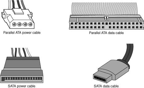
As I noted at the start of this chapter, Parallel ATA is a 16-bit parallel interface that is slowly being phased out in favor of the serial interface of SATA. Serial ATA’s thinner and smaller cables provide higher performance due to the higher cycling speeds allowed and are considerably easier to work with than the wide PATA ribbon cables. Figure 7.1 shows how the power and data cables used by SATA compare in size to those used by Parallel ATA.
Figure 7.1 Serial ATA data cables (lower right) are much smaller than those used by Parallel ATA (upper right), whereas the power cables (left) are similar in size.
ATA Standards
Today, the ATA interface is controlled by an independent group of representatives from major PC, drive, and component manufacturers. This group is called Technical Committee T13 (www.t13.org) and is responsible for all standards relating to the Parallel and Serial AT Attachment storage interfaces. T13 is a part of the International Committee on Information Technology Standards (INCITS), which operates under rules approved by the American National Standards Institute (ANSI), a governing body that sets rules that control nonproprietary standards in the computer industry as well as many other industries. A second group called the Serial ATA International Organization (www.serialata.org) was formed to initially create the Serial ATA standards, which are then passed on to the T13 Committee for refinement and official publication under ANSI. The ATA-7 and ATA-8 standards incorporate both parallel and serial interfaces.
The rules these committees operate under are designed to ensure that voluntary industry standards are developed by the consensus of people and organizations in the affected industry. INCITS specifically develops Information Processing System standards, whereas ANSI approves the process under which these standards are developed and then publishes them. Because T13 is essentially a public organization, all the working drafts, discussions, and meetings of T13 are open for all to see.
Copies of any of the published standards can be purchased from ANSI (www.ansi.org) or Global Engineering Documents (http://global.ihs.com). Draft versions of the standards can be downloaded from the T13 Committee or Serial ATA International Organization (SATA-IO) website.
Each newer version of ATA is backward compatible with the previous versions. In other words, older ATA-1 and ATA-2 devices work fine on ATA-6 and ATA-8 interfaces. ATA-7 and ATA-8 include both Parallel and Serial ATA. Newer versions of ATA are normally built on older versions, and with few exceptions can be thought of as extensions of the previous versions. This means that ATA-8, for example, is generally considered equal to ATA-7 with the addition of some features.
Table 7.2 breaks down the various ATA standards. The following sections describe all the ATA versions in more detail.

ATA-1 (AT Attachment Interface for Disk Drives)
ATA-1 defined the original AT Attachment interface, which was an integrated bus interface between disk drives and host systems based on the ISA (AT) bus. These major features were introduced and documented in the ATA-1 specification:
• 40/44-pin connectors and cabling
• Master/slave or cable select drive configuration options
• Signal timing for basic Programmed I/O (PIO) and direct memory access (DMA) modes
• Cylinder, head, sector (CHS) and logical block address (LBA) drive parameter translations supporting drive capacities up to 228−220 (267,386,880) sectors, or 136.9GB
Although ATA-1 had been in use since 1986, work on turning it into an official standard began in 1988 under the Common Access Method (CAM) committee. The ATA-1 standard was finished and officially published in 1994 as “ANSI X3.221-1994, AT Attachment Interface for Disk Drives.” ATA-1 was officially withdrawn as a standard on August 6, 1999.
Although ATA-1 supported theoretical drive capacities up to 136.9GB (228−220 = 267,386,880 sectors), it did not address BIOS limitations that stopped at 528MB (1024×16×63 = 1,032,192 sectors). The BIOS limitations would be addressed in subsequent ATA versions because, at the time, no drives larger than 528MB existed.
ATA-2 (AT Attachment Interface with Extensions-2)
ATA-2 first appeared in 1993 and was a major upgrade to the original ATA standard. Perhaps the biggest change was almost a philosophical one. ATA-2 was updated to define an interface between host systems and storage devices in general and not only disk drives. The major features added to ATA-2 as compared to the original ATA standard include the following:
• Faster PIO and DMA transfer modes
• Support for power management
• Support for removable devices
• PCMCIA (PC Card) device support
• Identify Drive command that reports more information
• Defined standard CHS/LBA translation methods for drives up to 8.4GB in capacity
The most important additions in ATA-2 were the support for faster PIO and DMA modes, as well as methods to enable BIOS support up to 8.4GB. The BIOS support was necessary because, although ATA-1 was designed to support drives of up to 136.9GB in capacity, the PC BIOS could originally handle drives of up to 528MB. Adding parameter-translation capability now allowed the BIOS to handle drives up to 8.4GB. This is discussed in more detail later in this chapter.
ATA-2 also featured improvements in the Identify Drive command that enabled a drive to tell the software exactly what its characteristics are; this is essential for both Plug and Play (PnP) and compatibility with future revisions of the standard.
ATA-2 was also known by unofficial marketing terms such as Fast-ATA or Fast-ATA-2 (Seagate/Quantum) and EIDE (Enhanced IDE, Western Digital).
Although work on ATA-2 began in 1993, the standard was not officially published until 1996 as “ANSI X3.279-1996 AT Attachment Interface with Extensions.” ATA-2 was officially withdrawn in 2001.
ATA-3 (AT Attachment Interface-3)
First appearing in 1995, ATA-3 was a comparatively minor revision to the ATA-2 standard that preceded it. It consisted of a general cleanup of the specification and had mostly minor clarifications and revisions. The most major changes included the following:
• Eliminated single-word (8-bit) DMA transfer protocols.
• Added S.M.A.R.T. (Self-Monitoring, Analysis, and Reporting Technology) support for prediction of device performance degradation.
• LBA mode support was made mandatory (previously it had been optional).
• Added ATA Security mode, allowing password protection for device access.
• Provided recommendations for source and receiver bus termination to solve noise issues at higher transfer speeds.
ATA-3 built on ATA-2, adding improved reliability, especially of the faster PIO mode 4 transfers; however, ATA-3 did not define any faster modes. ATA-3 did add a simple password-based security scheme, more sophisticated power management, and S.M.A.R.T. This enables a drive to keep track of problems that might result in a failure and thus avoid data loss. S.M.A.R.T. is a reliability prediction technology that IBM initially developed.
Work on ATA-3 began in 1995, and the standard was finished and officially published in 1997 as “ANSI X3.298-1997, AT Attachment 3 Interface.” ATA-3 was officially withdrawn in 2002.
ATA/ATAPI-4 (AT Attachment with Packet Interface Extension-4)
First appearing in 1996, ATA-4 included several important additions to the standard. It included the Packet Command feature known as the AT Attachment Packet Interface (ATAPI), which allowed devices such as CD-ROM and CD-RW drives, LS-120 SuperDisk floppy drives, Zip drives, tape drives, and other types of storage devices to be attached through a common interface. Until ATA-4 came out, ATAPI was a separately published standard. ATA-4 also added the 33MB per second (MBps) transfer mode known as Ultra-DMA or Ultra-ATA. ATA-4 is backward compatible with ATA-3 and earlier definitions of the ATAPI.
Work on ATA-4 began in 1996, and the standard was finished and officially published in 1998 as “ANSI NCITS 317-1998, AT Attachment - 4 with Packet Interface Extension.”
The major revisions added in ATA-4 were as follows:
• Ultra-DMA (UDMA) or Ultra-ATA/33) transfer modes up to Mode 2, which is 33MBps (called UDMA/33 or Ultra-ATA/33)
• Integral ATAPI support
• Advanced power management support
• An optional 80-conductor, 40-pin cable defined for improved noise resistance
• Host protected area (HPA) support
• Compact Flash Adapter (CFA) support
• Enhanced BIOS support for drives over 9.4ZB (zettabytes or trillion gigabytes) in size (even though ATA was still limited to 136.9GB)
The speed and level of ATA support in your system is mainly dictated by your motherboard chipset. Most motherboard chipsets come with a component called either a South Bridge or an I/O Controller Hub that provides the ATA interface (as well as other functions) in the system. Check the specifications for your motherboard or chipset to see whether yours supports the faster ATA/33, ATA/66, ATA/100, or ATA/133 mode. One indication is to enter the BIOS Setup, put the hard disk on manual parameter settings (user defined), and see which (if any) Ultra-DMA modes are listed. Most boards built during 1998 support ATA/33. In 2000 they began to support ATA/66, and by late 2000 most started supporting ATA/100. ATA/133 support became widespread in mid-2002.
![]() See “Chipsets,” p. 198 (Chapter 4).
See “Chipsets,” p. 198 (Chapter 4).
ATA-4 made ATAPI support a full part of the ATA standard; therefore, ATAPI was no longer an auxiliary interface to ATA but merged completely within it. Thus, ATA-4 promoted ATA for use as an interface for many other types of devices. ATA-4 also added support for new Ultra-DMA modes (also called Ultra-ATA) for even faster data transfer. The highest-performance mode, called UDMA/33, had 33MBps bandwidth—twice that of the fastest programmed I/O mode or DMA mode previously supported. In addition to the higher transfer rate, because UDMA modes relieve the load on the processor, further performance gains were realized.
An optional 80-conductor cable (with cable select) is defined for UDMA/33 transfers. Although this cable was originally defined as optional, it would later be required for the faster ATA/66, ATA/100, and ATA/133 modes in ATA-5 and later.
Support for a reserved area on the drive called the host protected area (HPA) was added via an optional SET MAX ADDRESS command. This enables an area of the drive to be reserved for recovery software.
Also included was support for queuing commands, similar to those provided in SCSI-2. This enabled better multitasking as multiple programs make requests for ATA transfers.
Another standard approved by the T13 committee in 1998 was “ANSI NCITS 316-1998 1394 to AT Attachment - Tailgate,” which is a bridge protocol between the IEEE 1394 (i.LINK/FireWire) bus and ATA that enables ATA drives to be adapted to FireWire. A tailgate is an adapter device (basically a small circuit board) that converts IEEE 1394 (i.LINK or FireWire) to ATA, essentially allowing ATA drives to be plugged into a FireWire bus. This has enabled vendors to quickly develop IEEE 1394 (FireWire) external drives for backup and high-capacity removable data storage. Inside almost any external FireWire drive enclosure you will find the tailgate device and a standard ATA drive.
![]() See “IEEE 1394 (FireWire or i.LINK),” p. 780 (Chapter 14, “External I/O Interfaces”).
See “IEEE 1394 (FireWire or i.LINK),” p. 780 (Chapter 14, “External I/O Interfaces”).
ATA/ATAPI-5 (AT Attachment with Packet Interface-5)
ATA-5 first appeared in 1998 and was built on the previous ATA-4 interface. ATA-5 includes Ultra-ATA/66 (also called Ultra-DMA or UDMA/66), which doubles the Ultra-ATA burst transfer rate by reducing setup times and increasing the clock rate. The faster clock rate increases interference, which causes problems with the standard 40-pin cable used by ATA and Ultra-ATA. To eliminate noise and interference, the newer 40-pin, 80-conductor cable was made mandatory for drives running in UDMA/66 or faster modes. This cable adds 40 additional ground lines between each of the original 40 ground and signal lines, which helps shield the signals from interference. Note that this cable works with older, non-Ultra-ATA devices as well because it still has the same 40-pin connectors.
Work on ATA-5 began in 1998, and the standard was finished and officially published in 2000 as “ANSI NCITS 340-2000, AT Attachment - 5 with Packet Interface.”
The major additions in the ATA-5 standard include the following:
• Ultra-DMA (UDMA) transfer modes up to Mode 4, which is 66MBps (called UDMA/66 or Ultra-ATA/66).
• The 80-conductor cable now mandatory for UDMA/66 operation.
• Automatic detection of 40- or 80-conductor cables.
• UDMA modes faster than UDMA/33 are enabled only if an 80-conductor cable is detected.
The 40-pin, 80-conductor cables support the cable select feature and have color-coded connectors. The blue (end) connector should be connected to the ATA host interface (usually the motherboard). The black (opposite end) connector is known as the master position, which is where the primary drive plugs in. The gray (middle) connector is for slave devices.
To use either the UDMA/33 or UDMA/66 mode, your ATA interface, drive, BIOS, and cable must be capable of supporting the mode you want to use. The operating system also must be capable of handling direct memory access. Windows 95 OSR2 and later versions are ready out of the box, but older versions of Windows 95 and NT (prior to Service Pack 3) require additional or updated drivers to fully exploit these faster modes. Contact the motherboard or system vendor for the latest drivers.
For reliability, Ultra-DMA modes incorporate an error-detection mechanism known as cyclical redundancy checking (CRC). CRC is an algorithm that calculates a checksum used to detect errors in a stream of data. Both the host (controller) and the drive calculate a CRC value for each Ultra-DMA transfer. After the data is sent, the drive calculates a CRC value, and this is compared to the original host CRC value. If a difference is reported, the host might be required to select a slower transfer mode and retry the original request for data.
ATA/ATAPI-6 (AT Attachment with Packet Interface-6)
ATA-6 began development during 2000 and includes Ultra-ATA/100 (also called Ultra-DMA or UDMA/100), which increases the Ultra-ATA burst transfer rate by reducing setup times and increasing the clock rate. As with ATA-5, the faster modes require the improved 80-conductor cable. Using the ATA/100 mode requires both a drive and motherboard interface that supports that mode.
Work on ATA-6 began in 2000, and the standard was finished and officially published in 2002 as “ANSI NCITS 361-2002, AT Attachment - 6 with Packet Interface.”
The major changes or additions in the standard include the following:
• Ultra-DMA (UDMA) Mode 5 added, which allows 100MBps (called UDMA/100, Ultra-ATA/100, or just ATA/100) transfers.
• Sector count per command increased from 8 bits (256 sectors, or 131KB) to 16 bits (65,536 sectors, or 33.5MB), allowing larger files to be transferred more efficiently.
• LBA addressing extended from 228 to 248 (281,474,976,710,656) sectors, supporting drives up to 144.12PB (petabytes = quadrillion bytes). This feature is often referred to as 48-bit LBA or greater than 137GB support by vendors; Maxtor referred to this feature as Big Drive.
• CHS addressing was made obsolete; drives must use 28-bit or 48-bit LBA addressing only.
Besides adding the 100MBps UDMA Mode 5 transfer rate, ATA-6 also extended drive capacity greatly, and just in time. ATA-5 and earlier standards supported drives of up to only 137GB in capacity, which became a limitation as larger drives were becoming available. Commercially available 3 1/2″ drives exceeding 137GB were introduced during 2001, but they were originally available only in SCSI versions because SCSI doesn’t have the same limitations as ATA. With ATA-6, the sector addressing limit has been extended from 228 sectors to 248 sectors. What this means is that LBA addressing previously could use only 28-bit numbers, but with ATA-6, LBA addressing can use larger 48-bit numbers if necessary. With 512 bytes per sector, this raises the maximum supported drive capacity to 144.12PB. That is equal to more than 144.12 quadrillion bytes! Note that the 48-bit addressing is optional and necessary only for drives larger than 137GB. Drives 137GB or smaller can use either 28-bit or 48-bit addressing.
ATA/ATAPI-7 (AT Attachment with Packet Interface-7)
Work on ATA-7, which began late in 2001, was completed and officially published in 2004. As with the previous ATA standards, ATA-7 is built on the standard that preceded it (ATA-6), with some additions.
The primary additions to ATA-7 include the following:
• Ultra-DMA (UDMA) Mode 6 was added. This allows for 133MBps transfers (called UDMA/133, Ultra-ATA/133, or just ATA/133). As with UDMA Mode 5 (100MBps) and UDMA Mode 4 (66MBps), the use of an 80-conductor cable is required.
• Added support for long physical sectors. This allows a device to be formatted so that there are multiple logical sectors per physical sector. Each physical sector stores an ECC field, so long physical sectors allow increased format efficiency with fewer ECC bytes used overall.
• Added support for long logical sectors. This enables additional data bytes to be used per sector (520 or 528 bytes instead of 512 bytes) for server applications. Devices using long logical sectors are not backward compatible with devices or applications that use 512-byte sectors, such as standard desktop and laptop systems.
• Serial ATA incorporated as part of the ATA-7 standard.
• The ATA-7 document split into three volumes. Volume 1 covers the command set and logical registers, Volume 2 covers the parallel transport protocols and interconnects, and Volume 3 covers the serial transport protocols and interconnects.
Note that although the throughput has been increased from the drive controller (on the drive) to the motherboard via the UDMA modes, most ATA drives—even those capable of UDMA Mode 6 (133MBps) from the drive to the motherboard—still have an average maximum sustained transfer rate while reading data of under 60MBps. This means that although newer ATA drives can transfer at speeds up to 133MBps from the circuit board on the drive to the motherboard, data from the drive media (platters) through the heads to the circuit board on the drive moves at less than half that rate. For that reason, running a drive capable of UDMA Mode 6 (133MBps) on a motherboard capable of only UDMA Mode 5 (100MBps) really doesn’t slow things down much, if at all. Likewise, upgrading your ATA host adapter from one that does 100MBps to one that can do 133MBps won’t help much if your drive reads data off the disk platters at only half that speed. Always remember that the media transfer rate is far more important than the interface transfer rate when selecting a drive because the media transfer rate is the limiting factor.
The ATA/133 transfer mode was originally proposed by Maxtor, and only a few other drive and chipset manufacturers adopted it. Among the chipset manufacturers, VIA, ALi, and SiS added ATA/133 support to their chipsets, prior to moving on to Serial ATA, but Intel decided from the outset to skip ATA/133 in its chipsets in lieu of adding Serial ATA (150MBps or 300MBps) instead. This means the majority of systems that utilize Parallel ATA do not have support for ATA/133; however, all ATA/133 drives do work in ATA/100 mode.
ATA/ATAPI-8
Work on ATA-8 began in 2004, and parts of the standard were published in 2008 and 2009. As with the previous ATA standards, ATA-8 is built on the standard that preceded it, with some additions. As with the previous version, ATA-8 includes SATA as well.
The main features of ATA-8 include the following:
• The replacement of read long/write long functions
• Improved HPA (host protected area) management
As the development of ATA progresses, it is expected that newer features designed by the SATA-IO committee will be incorporated, including the faster SATA 3Gbps and 6Gbps transfer speeds.
Parallel ATA
Parallel ATA has unique specifications and requirements regarding the physical interface, cabling, and connectors as compared to Serial ATA. The following sections detail the unique features of Parallel ATA.
Parallel ATA I/O Connector
The Parallel ATA interface connector is normally a 40-pin header-type connector with pins spaced 0.1″ (2.54mm) apart, and generally it is keyed to prevent the possibility of installing it upside down (see Figures 7.2 and 7.3). To create a keyed connector, the manufacturer usually removes pin 20 from the male connector and blocks pin 20 on the female cable connector, which prevents the user from installing the cable backward. Some cables also incorporate a protrusion on the top of the female cable connector that fits into a notch in the shroud surrounding the mating male connector on the device. The use of keyed connectors and cables is highly recommended. Plugging an ATA cable in backward normally doesn’t cause any permanent damage; however, it can lock up the system and prevent it from running.
Figure 7.2 Typical Parallel ATA (IDE) hard drive connectors.
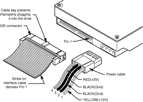
Figure 7.3 Parallel ATA (IDE) 40-pin interface connector detail.
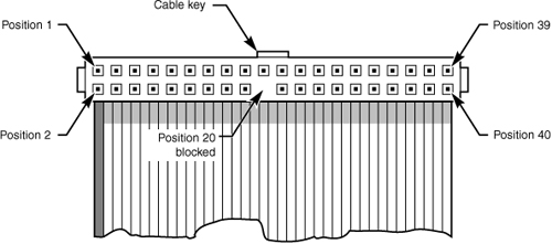
Table 7.3 shows the standard 40-pin Parallel ATA (IDE) interface connector pinout.
Table 7.3 Pinout for the 40-Pin Parallel ATA Connector

The 2 1/2″ drives found in notebook/laptop-size computers typically use a smaller unitized 50-pin header connector with pins spaced only 2.0mm (0.079″) apart. The main 40-pin part of the connector is the same as the standard Parallel ATA connector (except for the physical pin spacing), but there are added pins for power and jumpering. The cable that plugs into this connector typically has 44 pins, carrying power as well as the standard ATA signals. The jumper pins usually have a jumper on them (the jumper position controls cable select, master, or slave settings). Figure 7.4 shows the unitized 50-pin connector used on the 2 1/2″ Parallel ATA drives in laptop or notebook computers.
Figure 7.4 The 50-pin unitized Parallel ATA connector detail (used on 2 1/2″ notebook/laptop Parallel ATA drives with a 44-pin cable).
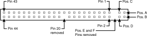
Note the jumper pins at positions A–D and that the pins at positions E and F are removed. A jumper usually is placed between positions B and D to set the drive for cable select operation. On this connector, pin 41 provides +5V power to the drive logic (circuit board), pin 42 provides +5V power to the motor (2 1/2″ drives use 5V motors, unlike larger drives that typically use 12V motors), and pin 43 provides a power ground. The last pin (44) is reserved and not used.
Table 7.4 shows the 50-pin unitized Parallel ATA interface connector pinout as used on most 2 1/2″ (laptop or notebook computer) drives.
Table 7.4 The 50-Pin Unitized Parallel ATA 2 1/2″ (Notebook/Laptop Drive) Connector Pinout

Note
Many lower-cost board and cable manufacturers leave out the keying. Cheaper motherboards often don’t have pin 20 removed on their ATA connectors; consequently, they don’t supply a cable with pin 20 blocked. If they don’t use a shrouded connector with a notch and a corresponding protrusion on the cable connector, no keying exists and the cables can be inserted backward. Fortunately, the only consequence of this in most cases is that the device won’t work until the cable is attached with the correct orientation.
Note that some systems do not display any video until the ATA drives respond to a spin-up command, which they can’t receive if the cable is connected backward. So, if you connect an unkeyed ATA drive to your computer, turn on the computer, and it seems as if the system is locked up (you don’t see anything on the screen), check the ATA cable. (See Figure 7.6 for examples of unkeyed and keyed ATA cables.)
In rare situations in which you are mixing and matching items, you might encounter a cable with pin 20 blocked (as it should be) and a board with pin 20 still present. In that case, you can break off pin 20 from the board—or for the more squeamish, remove the block from the cable or replace the cable with one without the blocked pin. Some cables have the block permanently installed as a part of the connector housing, in which case you must break off pin 20 on the board or device end or use a different cable.
The simple rule of thumb is that pin 1 should be oriented toward the power connector on the device, which normally corresponds to the stripe on the cable.
Parallel ATA I/O Cable
A 40-conductor ribbon cable is specified to carry signals between the bus adapter circuits and the drive (controller). To maximize signal integrity and eliminate potential timing and noise problems, the cable should not be longer than 18″ (0.46 meters), although testing shows that 80-conductor cables can be used reliably up to 27″ (0.69 meters) in length.
Note that ATA drives supporting the higher-speed transfer modes, such as PIO Mode 4 or any of the Ultra-DMA (UDMA) modes, are especially susceptible to cable integrity problems. If the cable is too long, you can experience data corruption and other errors that can be maddening. This is manifested in problems reading from or writing to the drive. In addition, any drive using UDMA Mode 5 (66MBps transfer rate), Mode 6 (100MBps transfer rate), or Mode 7 (133MBps transfer rate) must use a special, higher-quality 80-conductor cable. I also recommend this type of cable if your drive is running at UDMA Mode 2 (33MBps) or slower because it can’t hurt and can only help. I always keep a high-quality 80-conductor ATA cable in my toolbox for testing drives where I suspect cable integrity or cable length problems. Figure 7.5 shows the typical ATA cable layout and dimensions.
Figure 7.5 Parallel ATA (IDE) cable, with 40-pin connectors and either 40- or 80-conductor cables (additional wires are grounded in 80-conductor versions).

Note
Most 40-conductor cables do not have color-coded connectors, whereas all 80-conductor cables have color-coded connectors.
The two primary variations of Parallel ATA cables in use today—one with 40 conductors and the other with 80 conductors—are shown in Figure 7.6. As you can see, both use 40-pin connectors, and the additional wires in the 80-conductor version are simply wired to ground. The additional conductors are designed to reduce noise and interference and are required when setting the interface to run at 66MBps (ATA/66) or faster. The drive and host adapter are designed to disable the higher-speed ATA/66, ATA/100, and ATA/133 modes if an 80-conductor cable is not detected. In such cases, you might see a warning message when you start your computer if an ATA/66 or faster drive is connected to a 40-conductor cable. The 80-conductor cable can also be used at lower speeds; although this is unnecessary, it improves the signal integrity. Therefore, it is the recommended version no matter which drive you use.
Figure 7.6 A 40-conductor Parallel ATA cable (left) and a 80-conductor Parallel ATA cable (right).
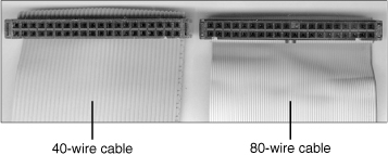
I once had a student ask me how to tell an 80-conductor cable from a 40-conductor cable. The simple answer is to count the ridges (conductors) in the cable. If you count only 40, it must be a 40-conductor cable, and if you count to 80...well, you get the idea! If you observe them side by side, the difference is clear: The 80-conductor cable has an obviously smoother, less ridged appearance than the 40-conductor cable.
Note the keying on the 80-conductor cable that is designed to prevent backward installation. Note also that the poorly constructed 40-conductor cable shown in this example lacks keying. Most good 40-conductor cables include the keying; however, because it is optional, many cheaply constructed versions do not include it. Keying was made mandatory for all 80-conductor cables as part of the standard.
Longer and/or Rounded Cables
The official Parallel ATA standard limits cable length to 18″ (0.46 meters); however, many of the cables sold are longer, up to even 36″ (0.91 meters) or more in length. I’ve had many readers write me questioning the length, asking, “Why would people sell cables longer than 18″ if the standard doesn’t allow it?” Well, just because something is for sale doesn’t mean it conforms to the standards and will work properly! I see improperly designed, poorly manufactured, and nonconforming items for sale all the time. Still, many people have used the longer cables and yet their systems seem to work fine, but I’ve also documented numerous cases where using longer cables has caused problems, so I decided to investigate this issue more thoroughly.
What I’ve discovered is that you can use longer 80-conductor cables reliably up to 27″ (0.69 meters) in length, but 40-conductor cables should remain limited to 18″, just as the standard indicates.
In fact, an attempt was made to change the Parallel ATA standard to allow 27″ cables. If you read www.t13.org/Documents/UploadedDocuments/technical/e00151r0.pdf, you’ll see data from a proposal that shows “negligible differences in Ultra DMA Mode 5 signal integrity between a 27″, 80-conductor cable and an 18″, 80-conductor cable.” This extended cable design was actually proposed back in October 2000, but it was never incorporated into the standard. Even though it was never officially approved, I take the information presented in this proposal as empirical evidence for allowing the use of 80-conductor cables up to 27″ in length without problems.
To that, I would add another recommendation, which is that in general I do not recommend “rounded” ATA cables. A rounded design has not been approved in the ATA standard, and there is some evidence that it can cause problems with crosstalk and noise. The design of 80-conductor cables is such that a ground wire is interspersed between each data wire in the ribbon, and rounding the cable causes some of the data lines to run parallel or adjacent to each other at random, thereby causing crosstalk and noise and resulting in signal errors.
Of course, many people use rounded cables with success, but my knowledge of electrical engineering as well as the ATA standard has always made me somewhat uncomfortable with their use.
Parallel ATA Signals
This section describes some of the most important Parallel ATA signals having to do with drive configuration and installation in more detail. This information can help you understand how the cable select feature works, for example.
Pin 20 is used as a key pin for cable orientation and is not connected to the interface. This pin should be missing from any ATA connectors, and the cable should have the pin-20 hole in the connector plugged off to prevent the cable from being plugged in backward.
Pin 39 carries the drive active/slave present (DASP) signal, which is a dual-purpose, time-multiplexed signal. During power-on initialization, this signal indicates whether a slave drive is present on the interface. After that, each drive asserts the signal to indicate that it is active. Early drives could not multiplex these functions and required special jumper settings to work with other drives. Standardizing this function to allow for compatible dual-drive installations is one of the features of the ATA standard. This is why some drives require a slave present (SP) jumper, whereas others do not.
Pin 28 carries the cable select signal (CSEL). In some older drives, it could also carry a spindle synchronization signal (SPSYNC), but that is not commonly found on newer drives. The CSEL function is the most widely used and is designed to control the designation of a drive as master (drive 0) or slave (drive 1) without requiring jumper settings on the drives. If a drive sees the CSEL as being grounded, the drive is a master; if CSEL is open, the drive is a slave.
You can install special cabling to ground CSEL selectively. This installation usually is accomplished through a cable that has pin 28 missing from the middle connector, but present in the connectors on each end. In that arrangement, with one end plugged into the motherboard, and two drives set to cable select, the drive plugged into the end connector will automatically be configured as master, whereas the drive attached to the middle connector will be configured as slave. Note that although this is the most common arrangement, it is also possible to make cables where the middle connector is master (and the end is slave), or even to use a Y-cable arrangement, with the motherboard ATA bus connector in the middle, and each drive at opposite ends of the cable. In this arrangement, one leg of the Y would have the CSEL line connected through (master), and the other leg has the CSEL line open (conductor interrupted or removed), making the drive at that end the slave.
Parallel ATA Dual-Drive Configurations
Dual-drive Parallel ATA installations can be problematic because each drive has its own controller, and both controllers must function while being connected to the same bus. There has to be a way to ensure that only one of the two controllers respond to a command at a time.
The ATA standard provides the option of operating on the AT bus with two drives in a daisy-chained configuration. The primary drive (drive 0) is called the master, and the secondary drive (drive 1) is called the slave. You designate a drive as being master or slave by setting a jumper or switch on the drive or by using a special line in the interface called the cable select (CS) pin and setting the CS jumper on the drive.
When only one drive is installed, the controller responds to all commands from the system. When two drives (and, therefore, two controllers) are installed, both controllers receive all commands from the system. Each controller then must be set up to respond only to commands for itself. In this situation, one controller must be designated as the master and the other as the slave. When the system sends a command for a specific drive, the controller on the other drive must remain silent while the selected controller and drive are functioning. Setting the jumper to master or slave enables discrimination between the two controllers by setting a special bit (the DRV bit) in the drive/head register of a command block.
Configuring ATA drives can be simple, as is the case with most single-drive installations. Or it can be troublesome, especially when it comes to mixing two older drives from different manufacturers on a single cable.
Most ATA drives can be configured with four possible settings:
• Master (single drive)
• Master (dual drive)
• Slave (dual drive)
• Cable select
Most drives simplify this to three settings: master, slave, and cable select. Because each ATA drive has its own controller, you must specifically tell one drive to be the master and the other to be the slave. No functional difference exists between the two, except that the drive that’s specified as the slave will assert a signal called DASP after a system reset informs the master that a slave drive is present in the system. The master drive then pays attention to the drive select line, which it otherwise ignores. Telling a drive that it’s the slave also usually causes it to delay its spin-up for several seconds to allow the master to get going and thus to lessen the load on the system’s power supply.
Until the ATA specification, no common implementation for drive configuration was in use. Some drive companies even used different master/slave methods for different models of drives. Because of these incompatibilities, some drives work together only in a specific master/slave or slave/master order. This situation mostly affects older IDE drives introduced before the ATA specification.
Most drives that fully follow the ATA specification now need only one jumper (master/slave) for configuration. A few also need a slave present jumper as well. Table 7.5 shows the jumper settings that most ATA drives require.
Table 7.5 Jumper Settings for Most ATA-Compatible Drives on Standard (Non–Cable Select) Cables

Note
If a cable select cable is used, the CS jumper should be set to On and all others should be set to Off. The cable connector then determines which drive will be master or slave.
Figure 7.7 shows the jumpers on a typical ATA drive.
Figure 7.7 Parallel ATA (IDE) drive jumpers for most drives.
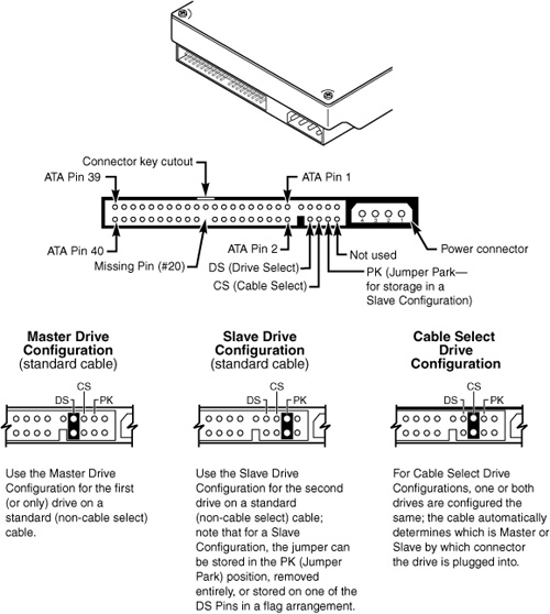
The master jumper indicates that the drive is a master or a slave. Some drives also require a slave present jumper, which is used only in a dual-drive setup and then installed only on the master drive—which is somewhat confusing. This jumper tells the master that a slave drive is attached. With many Parallel ATA drives, the master jumper is optional and can be left off. Installing this jumper doesn’t hurt in these cases and can eliminate confusion; I recommend that you install the jumpers listed here.
Note
Note that some drives have these jumpers on the drive circuit board on the bottom of the drive, and as such they might not be visible on the rear.
To eliminate confusion over master/slave settings, most newer systems now use the cable select option. This involves two things. The first is having a special Parallel ATA cable that has all the wires except pin 28 running from the motherboard connector to both drive connectors. Pin 28 is used for cable select and is connected to one of the drive connectors (labeled master) and not to the other (labeled slave). Both drives are then configured in cable select mode via the CS jumper on each drive.
With cable select, the drive that receives signals on pin 28 automatically becomes the master, and the other becomes the slave. Most cables implement this by removing the metal insulation displacement bit from the pin-28 hole, which can be difficult to see at a glance. Other cables have a section of pin 28 visibly cut from the cable somewhere along the ribbon. Because this is such a minor modification to the cable and can be difficult to see, cable select cables typically have the connectors labeled master, slave, and system, indicating that the cable controls these options rather than the drive. All 80-conductor Ultra-ATA cables are designed to use cable select.
With cable select, you simply set the CS jumper on all drives and then plug the drive you want to be the master into the connector labeled master on the cable and the drive you want to be the slave into the connector labeled slave.
The only downside I see to using cable select is that it can restrict how the cable is routed or where you mount the drive that is to be master versus slave because they must be plugged into specific cable connector positions.
Parallel ATA PIO Transfer Modes
ATA-2 and ATA-3 defined the first of several higher-performance modes for transferring data over the Parallel ATA interface, to and from the drive. These faster modes were the main part of the newer specifications and were the main reason they were initially developed. The following section discusses these modes.
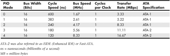
The PIO (programmed I/O) mode determines how fast data is transferred to and from the drive using PIO transfers. In the slowest possible mode—PIO Mode 0—the data cycle time can’t exceed 600 nanoseconds (ns). In a single cycle, 16 bits are transferred in to or out of the drive, making the theoretical transfer rate of PIO Mode 0 (600ns cycle time) 3.3MBps, whereas PIO Mode 4 (120ns cycle time) achieves a 16.6MBps transfer rate.
Table 7.6 shows the PIO modes, with their respective transfer rates.
Table 7.6 PIO Modes and Transfer Rates
Most motherboards with ATA-2 or greater support have dual ATA connectors on the motherboard. Most of the motherboard chipsets include the ATA interface in their South Bridge components, which in most systems is tied into the PCI bus.
Older 486 and some early Pentium boards have only the primary connector running through the system’s PCI local bus. The secondary connector on those boards usually runs through the ISA bus and therefore supports up to Mode 2 operation only.
When interrogated with an Identify Drive command, a hard disk returns, among other things, information about the PIO and DMA modes it is capable of using. Most enhanced BIOSs automatically set the correct mode to match the capabilities of the drive. If you set a mode faster than the drive can handle, data corruption results.
ATA-2 and newer drives also perform Block Mode PIO, which means they use the Read/Write Multiple commands that greatly reduce the number of interrupts sent to the host processor. This lowers the overhead, and the resulting transfers are even faster.
Parallel ATA DMA Transfer Modes
ATA drives also support direct memory access (DMA) transfers. DMA means that the data is transferred directly between drive and memory without using the CPU as an intermediary, as opposed to PIO. This has the effect of offloading much of the work of transferring data from the processor, in effect allowing the processor to do other things while the transfer is taking place.
There are two distinct types of direct memory access: singleword (8-bit) and multiword (16-bit) DMA. Singleword DMA modes were removed from the ATA-3 and later specifications and are obsolete. DMA modes are also sometimes called busmaster ATA modes because they use a host adapter that supports busmastering. Ordinary DMA relies on the legacy DMA controller on the motherboard to perform the complex task of arbitration, grabbing the system bus and transferring the data. In the case of busmastering DMA, all this is done by a higher-speed logic chip in the host adapter interface (which is also on the motherboard).
Systems using the Intel PIIX (PCI IDE ISA eXcelerator) and later South Bridge chips (or equivalent) have the capability of supporting busmaster ATA. The singleword and multiword busmaster ATA modes and transfer rates are shown in Tables 7.7 and 7.8, respectively.
Table 7.7 Singleword (8-bit) DMA Modes and Transfer Rates

Table 7.8 Multiword (16-bit) DMA Modes and Transfer Rates

Note that multiword DMA modes are also called busmaster DMA modes by some manufacturers. Unfortunately, even the fastest multiword DMA Mode 2 results in the same 16.67MBps transfer speed as PIO Mode 4. However, even though the transfer speed is the same as PIO, because DMA offloads much of the work from the processor, overall system performance is higher. Even so, multiword DMA modes were never very popular and have been superseded by the newer Ultra-DMA modes supported in devices that are compatible with ATA-4 through ATA-7.
Table 7.9 shows the Ultra-DMA modes now supported in the ATA-4 through ATA-7 specifications. Note that you need to install the correct drivers for your host adapter and version of Windows to use this feature.
Table 7.9 Ultra-DMA Support in ATA-4 Through ATA-7

Serial ATA
With the development of ATA-8, it seems that the Parallel ATA standard that has been in use for more than 10 years has finally reached the end of the line. Sending data at rates faster than 133MBps down a parallel ribbon cable is fraught with all kinds of problems because of signal timing, electromagnetic interference (EMI), and other integrity problems. The solution is called Serial ATA, which is an evolutionary replacement for the venerable Parallel ATA physical storage interface. When set in non-AHCI/RAID modes, Serial ATA is software-compatible with Parallel ATA, which means it emulates all the commands, registers, and controls so existing software will run without any changes. In other words, the existing BIOSs, operating systems, and utilities that work on Parallel ATA also work with Serial ATA.
Of course, they do differ physically—that is, you can’t plug Parallel ATA drives into Serial ATA host adapters, and vice versa, although signal converters make that possible. The physical changes are all for the better because Serial ATA uses much smaller and thinner cables with only seven conductors that are easier to route inside the PC and easier to plug in with smaller, redesigned cable connectors. The interface chip designs also are improved with far fewer pins and lower voltages. These improvements are all designed to eliminate the design problems inherent in Parallel ATA.
Figure 7.8 shows the official Serial ATA International Organization working group logo used to identify most Serial ATA devices.
Figure 7.8 Serial ATA official logo, which is used to identify SATA devices.

Although Serial ATA didn’t immediately replace Parallel ATA, most new systems following Serial ATA’s standardization included Serial ATA interfaces alongside Parallel ATA interfaces. Over time, SATA has predominantly replaced Parallel ATA as the de facto standard internal storage device interface found in PCs. The transition from ATA to SATA has been a gradual one, and during this transition Parallel ATA capabilities continue to be available.
Development for Serial ATA started when the Serial ATA Working Group effort was announced at the Intel Developer Forum in February 2000. The initial members of the Serial ATA Working Group included APT Technologies, Dell, IBM, Intel, Maxtor, Quantum, and Seagate. The original group later became known as the Serial ATA II Working Group, and finally in July 2004 it became the Serial ATA International Organization. The following SATA specifications have been released by these groups:
• The first Serial ATA 1.0 draft specification was released in November 2000 and was officially published as a final specification in August 2001.
• The first Serial ATA II Working Group extensions to this specification, which made Serial ATA suitable for network storage, were released in October 2002.
• SATA Revision 2 was released in April 2004. It added the 3Gbps (300MBps) signaling speed.
• SATA Revision 2.5 was released in August 2005. In addition to 3Gbps signaling, it added Native Command Queuing (NCQ), staggered spin-up, hot plug, port multiplier, and eSATA support.
• SATA Revision 2.6 was released in March 2007. It added new internal Slimline and Micro cables and connectors as well as modifications to Native Command Queuing (NCQ).
• SATA Revision 3.0 was released in 2009. It added the 6Gbps (600MBps) signaling speed.
The specifications can be downloaded from the Serial ATA International Organization website at www.serialata.org. Since forming, the group has grown to include more than 200 Contributor and Adopter companies from all areas of industry.
Systems using Serial ATA were first released in late 2002 using discrete PCI interface boards and chips. SATA was first integrated directly into motherboard chipsets in April 2003 with the introduction of the Intel ICH5 chipset component. Since then, virtually all new motherboard chipsets have included Serial ATA.
The performance of SATA is impressive, although current hard drive designs can’t fully take advantage of its bandwidth. This may change somewhat as hybrid drives incorporating larger flash memory caches as well as high performance SSDs (solid-state drives) arrive on the scene. Three variations of the standard have been proposed that all use the same cables and connectors; they differ only in transfer rate performance. Table 7.10 shows the specifications; the second-generation 300MBps (3.0Gbps) version became available in 2005, whereas the third-generation 600MBps (6.0Gbps) versions became available in 2009.
Table 7.10 Serial ATA Transfer Modes

From Table 7.10, you can see that Serial ATA sends data only a single bit at a time. The cable used has only seven wires (four signal and three ground) and is a very thin design, with keyed connectors only 14mm (0.55″) wide on each end. This eliminates problems with airflow compared to the wider Parallel ATA ribbon cables. Each cable has connectors only at each end, and each cable connects the device directly to the host adapter (typically on the motherboard). There are no master/slave settings because each cable supports only a single device. The cable ends are interchangeable—the connector on the motherboard is the same as on the device, and both cable ends are identical. Maximum SATA cable length is 1 meter (39.37″), which is considerably longer than the 18″ maximum for Parallel ATA. Even with this thinner, longer, and less-expensive cable, you initially get transfer rates of 150MBps (nearly 13% greater than Parallel ATA/133). Second-generation Serial ATA supports 300Mbps, and third-generation SATA supports 600Mbps.
Serial ATA uses a special encoding scheme called 8B/10B to encode and decode data sent along the cable. The 8B/10B transmission code originally was developed (and patented) by IBM in the early 1980s for use in high-speed data communications. Many high-speed data transmission standards, including Gigabit Ethernet, Fibre Channel, FireWire, and others, use this encoding scheme. The main purpose of the 8B/10B encoding scheme is to guarantee that never more than four 0s (or 1s) are transmitted consecutively. This is a form of Run Length Limited (RLL) encoding called RLL 0,4, in which the 0 represents the minimum and the 4 represents the maximum number of consecutive 0s or 1s in each encoded character.
The 8B/10B encoding also ensures that there are never more than six or fewer than four 0s (or 1s) in a single encoded 10-bit character. Because 1s and 0s are sent as voltage changes on a wire, this ensures that the spacing between the voltage transitions sent by the transmitter is fairly balanced, with a more regular and steady stream of pulses. This presents a steadier load on the circuits, increasing reliability. The conversion from 8-bit data to 10-bit encoded characters for transmission leaves several 10-bit patterns unused. Many of these additional patterns are used to provide flow control, delimit packets of data, perform error checking, or perform other special functions.
Serial ATA Cables and Connectors
The physical transmission scheme for SATA uses differential NRZ (Non Return to Zero). This uses a balanced pair of wires, each carrying +0.25V (one-quarter volt). The signals are sent differentially: If one wire in the pair carries +0.25V, the other wire carries -0.25V, where the differential voltage between the two wires is always 0.5V (one-half volt). So, for a given voltage waveform, the opposite voltage waveform is sent along the adjacent wire. Differential transmission minimizes electromagnetic radiation and makes the signals easier to read on the receiving end.
A 15-pin power cable and power connector is optional with SATA, providing 3.3V power in addition to the 5V and 12V provided via the industry-standard 4-pin device power connectors. Although it has 15 pins, this new power connector design is only 24mm (0.945″). With 3 pins designated for each of the 3.3V, 5V, and 12V power levels, enough capacity exists for up to 4.5 amps of current at each voltage, which is plenty for even the most power-hungry drives. For compatibility with existing power supplies, SATA drives can be made with the original, standard 4-pin device power connector or the new 15-pin SATA power connector (or both). If the drive doesn’t have the type of connector you need, adapters are available to convert from one type to the other.
Figure 7.9 shows what the new SATA signal and power connectors look like.
Figure 7.9 SATA (Serial ATA) signal and power connectors on a typical SATA hard drive.

Figure 7.10 shows SATA and Parallel ATA host adapters on a typical motherboard.
Figure 7.10 A motherboard with Serial and Parallel ATA host adapters.

The pinouts for the Serial ATA data and optional power connectors are shown in Tables 7.11 and 7.12, respectively.
Table 7.11 Serial ATA Data Connector Pinout

Table 7.12 Serial ATA Optional Power Connector Pinout

Serial ATA Configuration
Configuration of Serial ATA devices is also much simpler because the master/slave or cable select jumper settings used with Parallel ATA are no longer necessary.
BIOS setup for Serial ATA drives is also quite simple. Because Serial ATA is based on ATA, autodetection of drive settings on systems with Serial ATA connectors is performed in the same way as on Parallel ATA systems. Depending on the system, Serial ATA interfaces might be enabled by default or might need to be enabled in the BIOS setup program (see Chapter 5, “BIOS,” for details).
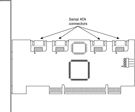
If you want to use Serial ATA drives but don’t want to install a new motherboard with Serial ATA host adapters already included, you can install a separate Serial ATA host adapter into a PCI expansion slot (see Figure 7.11). Most of these adapters include ATA RAID functions.
Figure 7.11 Typical 4-port Serial ATA RAID host adapter.
Some of the first Serial ATA host adapters, such as models from HighPoint and 3Ware, use a Parallel-to-Serial ATA bridge technology that consumes as much as half of the available bandwidth. Other adapters, such as those made by Promise Technology, use native Serial ATA controller chips, which is a better solution in theory because it preserves all the bandwidth for use by the drive. However, current Serial ATA drives, like their Parallel ATA siblings, cannot transfer data at anything close to the 150MBps rate of the host adapter; 40MBps–50MBps is the typical range for average transfer speeds of 7200 rpm Serial ATA drives.
Advanced Host Controller Interface (AHCI)
Serial ATA was designed not only as a replacement for Parallel ATA, but also as an interface that would evolve into something with many more capabilities and features than its predecessor. Initially, compatibility with Parallel ATA was one of the most important features of Serial ATA because it enabled a smooth and easy transition from one to the other. This compatibility extends to the driver level, allowing Serial ATA devices to use the same BIOS-level drivers and software as legacy Parallel ATA devices.
Although the intent of Serial ATA was to allow an easy transition from Parallel ATA, it was also designed to allow future growth and expansion of capabilities. To accomplish this, an enhanced software interface called the Advanced Host Controller Interface (AHCI) was initially developed by the AHCI Contributor Group, a group chaired by Intel and originally consisting of AMD, Dell, Marvell, Maxtor, Microsoft, Red Hat, Seagate, and StorageGear. The AHCI Contributor Group released a preliminary version of AHCI v0.95 in May 2003 and released the 1.0 version of the specification in April 2004. The current version (1.3) can be downloaded from Intel at www.intel.com/technology/serialata/ahci.htm.
AHCI provides an industry-standard, high-performance interface to system driver/OS software for discovering and implementing such advanced SATA features as command queuing, hot-plugging, and power management. AHCI was integrated into Serial ATA–supporting chipsets in 2004 and is supported by AHCI drivers for Windows. The main idea behind AHCI is to have a single driver-level interface supported by all advanced SATA host adapters. This greatly simplifies the installation of operating systems, eliminating the need for custom SATA drivers for each different manufacturer’s SATA host adapter. For example, Windows Vista and later include AHCI drivers and will automatically support any advanced SATA host adapters that are AHCI compatible.
Unfortunately, AHCI drivers are not included by default on the Windows XP and earlier installation CDs, because AHCI was developed long after XP was released. This means, for example, that if you install Windows XP on a system with an integrated SATA host adapter set to AHCI mode, you will probably need to press the F6 key at the beginning of the installation and provide a floppy disk with the AHCI drivers; otherwise, Windows XP will not be able to recognize the drives. The implication here is that the system must include a floppy drive, and you must have copied the drivers to a floppy disk in advance. But what if your system doesn’t even include a floppy drive? Fortunately, several solutions are available.
One option is to keep a spare floppy drive in your toolkit and temporarily connect it during the installation. Just open the case, plug in a floppy cable from the floppy drive connector (FDC) on the motherboard to the drive, and connect power to the drive. There is no need to actually mount the drive in the chassis, because you will only need to read the disk once at the beginning of the installation.
Another option is to set the SATA host adapter to ATA/IDE compatibility mode (disable AHCI/RAID) in the BIOS Setup, after which you can boot from a standard Windows XP CD and install Windows without requiring any special drivers. You could leave the adapter in compatibility mode, but you might be missing out on the performance offered by the advanced capabilities supported by your hard drives.
Although the first two options can work in most situations, I think the best overall solution is to simply create a custom Windows XP installation disc that already has the SATA AHCI (and even RAID) drivers preinstalled. This can be accomplished via a somewhat tedious manual integration process for each different set of drivers, but to make things really easy you can use the menu-driven BTS DriverPacks from www.driverpacks.net to integrate virtually all of the popular mass storage drivers directly into your Windows XP install disc. The DriverPacks allow you to easily add all kinds of drivers to your Windows XP installation discs. For example, in addition to the mass storage drivers, I also like to integrate the various processor, chipset, and network (both wired and wireless) drivers, because all of these will still fit on a CD. If you are willing to move to a DVD instead of a CD, you can fit all of the available DriverPacks on a single DVD.
Serial ATA Transfer Modes
Serial ATA transfers data in a completely different manner from Parallel ATA. As indicated previously, the transfer rates are 1.5Gbps (150MBps), 3.0GBps (300MBps), and 6.0GBps (600MBps), with most drives today supporting either the 1.5GBps and 3.0GBps rate. Note that speeds are backward compatible—for example, all drives supporting the 3.0GBps rate also work at 1.5GBps. Note that because SATA is designed to be backward compatible with Parallel ATA, some confusion can result because the BIOS and drives can report speeds and modes that emulate Parallel ATA settings for backward compatibility.
For example, many motherboards detect and report a Serial ATA drive as supporting Ultra DMA Mode 5 (ATA/100), which is a Parallel ATA mode operating at 100MBps. This is obviously incorrect because even the slowest Serial ATA mode (1.5GBps) is 150MBps and Ultra DMA modes simply do not apply to Serial ATA drives.
Parallel and Serial ATA are completely different electrical and physical specifications, but Serial ATA does emulate Parallel ATA in a way that makes it completely software transparent. In fact, the Parallel ATA emulation in Serial ATA specifically conforms to the ATA-5 specification.
This is especially apparent in the IDENTIFY DEVICE command used by the autodetect routines in the BIOS to read the drive parameters. The Serial ATA specification indicates that many of the items returned by IDENTIFY DEVICE are to be “set as indicated in ATA/ATAPI-5,” including available UDMA modes and settings.
The SATA 1 specification also says, “Emulation of parallel ATA device behavior, as perceived by the host BIOS or software driver, is a cooperative effort between the device and the Serial ATA host adapter hardware. The behavior of Command and Control Block registers, PIO and DMA data transfers, resets, and interrupts are all emulated. The host adapter contains a set of registers that shadow the contents of the traditional device registers, referred to as the Shadow Register Block. All Serial ATA devices behave like Device 0 devices. Devices shall ignore the DEV bit in the Device/Head field of received Register FISs, and it is the responsibility of the host adapter to gate transmission of Register FISs to devices, as appropriate, based on the value of the DEV bit.”
This means the shadow register blocks are “fake” Parallel ATA registers, allowing all ATA commands, modes, and so on to be emulated. Serial ATA was designed to be fully software compatible with ATA/ATAPI-5, which is why a Serial ATA drive can report in some ways as if it were Parallel ATA or running in Parallel ATA modes, even though it isn’t.
ATA Features
The ATA standards have gone a long way toward eliminating incompatibilities and problems with interfacing IDE drives to ISA/PCI bus systems. The ATA specifications define the signals on the 40-pin connector, the functions and timings of these signals, cable specifications, and so on. The following section lists some of the elements and functions defined by the ATA specifications.
ATA Commands
One of the best features of the ATA interface is the enhanced command set. The ATA interface was modeled after the WD1003 controller IBM used in the original AT system. All ATA drives must support the original WD command set (eight commands) with no exceptions, which is why ATA drives are so easy to install in systems today. All IBM-compatible systems have built-in ROM BIOS support for the WD1003, so they essentially support ATA as well.
In addition to supporting all the WD1003 commands, the ATA specification added numerous other commands to enhance performance and capabilities. These commands are an optional part of the ATA interface, but several of them are used in most drives available today and are very important to the performance and use of ATA drives in general.
Perhaps the most important is the IDENTIFY DRIVE command. This command causes the drive to transmit a 512-byte block of data that provides all details about the drive. Through this command, any program (including the system BIOS) can find out exactly which type of drive is connected, including the drive manufacturer, model number, operating parameters, and even the serial number of the drive. Many modern BIOSs use this information to automatically receive and enter the drive’s parameters into CMOS memory, eliminating the need for the user to enter these parameters manually during system configuration. This arrangement helps prevent mistakes that can later lead to data loss when the user no longer remembers what parameters he used during setup.
The Identify Drive data can tell you many things about your drive, including the following:
• Number of logical block addresses available using LBA mode
• Number of physical cylinders, heads, and sectors available in P-CHS mode
• Number of logical cylinders, heads, and sectors in the current translation L-CHS mode
• Transfer modes (and speeds) supported
• Manufacturer and model number
• Internal firmware revision
• Serial number
• Buffer type/size, indicating sector buffering or caching capabilities
Several freely available programs can execute this command and report the information onscreen, including ATAINF, which is available as part of a free collection of diagnostic tools called the Ultimate Boot CD. You can download the entire disc or most of the utilities individually from www.ultimatebootcd.com/. I find these programs especially useful when I am trying to install ATA drives on a system that has a user-defined drive type but doesn’t support autodetection and I need to know the correct parameters for a user-definable BIOS type. These programs get the information directly from the drive.
Two other important commands are the Read Multiple and Write Multiple commands. These commands permit multiple-sector data transfers and, when combined with block-mode PIO capabilities in the system, can result in incredible data-transfer rates many times faster than single-sector PIO transfers. Some older systems require you to select the correct number of sectors supported by the drive, but most recent systems automatically determine this information for you.
Many other enhanced commands are available, including room for a given drive manufacturer to implement what are called vendor-unique commands. Certain vendors often use these commands for features unique to that vendor. Often, vendor-unique commands control features such as low-level formatting and defect management. This is why low-level format programs can be so specific to a particular manufacturer’s ATA drives and why many manufacturers make their own LLF programs available.
ATA Security Mode
Support for hard disk passwords (called ATA Security Mode) was added to the ATA-3 specification during 1995. The proposal adopted in the ATA specification was originally from IBM, which had developed this capability and had already begun incorporating it into ThinkPad systems and IBM 2.5″ drives. Because it was then incorporated into the official ATA-3 standard (finally published in 1997), most other drive and system manufacturers have also adopted this, especially for laptop systems and 2.5″ drives. Note that these passwords are very secure. If you lose or forget them, they usually cannot be recovered and you will never be able to access the drive.
Hard disk security passwords are set via the BIOS Setup, however not all systems support this feature. Most laptops support hard disk security, but most desktops do not. If supported, two types of hard disk passwords can be set, called user and master. The user password locks and unlocks the disk, whereas the master password is used to only unlock. You can set a user password only, or you can set user+master, but you cannot set a master password alone.
When a user password is set (with no master), or when both user+master passwords are set, access to the drive is prevented (even if the drive is moved to a different system), unless the user (or master) password is entered upon system startup.
The master password is designed to be an alternative or backup password for system administrators as a master unlock. With both master and user passwords set, the user is told the user password but not the master password. Subsequently, the user can change the user password as desired; however, a system administrator can still gain access by using the master password.
If a user or user+master password is set, the disk must be unlocked at boot time via a BIOS-generated password prompt. The appearance of the prompt varies from system to system. For example in ThinkPad systems an icon consisting of a cylinder with a number above it (indicating the drive number) next to a padlock appears onscreen. If the hard disk password prompt appears, you must enter it; otherwise, you will be denied access to the drive and the system will not boot.
As with many security features, a workaround might be possible if you forget your password. In this case, at least one company can either restore the drive to operation (with all the data lost) or restore the drive and the data. That company is Nortek (see www.nortek.on.ca for more information). The password-removal procedure is relatively expensive (more than the cost of a new drive in most cases), and you must provide proof of ownership when you send in the drive. As you can see, it is worthwhile only if you absolutely need the data back.
Hard disk passwords are not preset on a brand-new drive, but they might be preset if you are buying a used drive or if the people or company you purchased the drive or system from entered them. This is a common ploy when selling drives or systems (especially laptops) on eBay—for example, the seller might set supervisor or hard disk passwords and hold them until payment is received. Or he might be selling a used product “as is,” for which he doesn’t have the passwords, which renders them useless to the purchaser. Be sure that you do not purchase a used laptop or hard drive unless you are certain that no supervisor or hard disk passwords are set.
Most systems also support other power-on or supervisor passwords in the BIOS Setup. In most systems, when you set a supervisor password, it automatically sets the hard disk password to the same value as well. In most cases, if a supervisor password is set and it matches the hard disk user or master password, when you enter the supervisor password, the BIOS automatically enters the hard disk password at the same time. This means that even though a hard disk password is set, you might not even know it because the hard disk password is entered automatically at the same time as you enter the supervisor password; therefore, you won’t see a separate prompt for the hard disk password. However, if the drive is later separated from the system, it will not work on another system until the correct hard disk password is entered. Without the services of a company such as Nortek, you can remove a hard disk password only if you know the password to begin with.
Host Protected Area
Most PCs sold on the market today include some form of automated product recovery or restoration feature that allows a user to easily restore the operating system and other software on the system to the state it was in when the system was new. Originally, this was accomplished via one or more product-recovery CDs containing automated scripts that reinstalled all the software that came preinstalled on the system when it was new.
Unfortunately, the CDs could be lost or damaged, they were often problematic to use, and including them by default cost manufacturers a lot of money. This prompted PC manufacturers to move the recovery software to a hidden partition of the boot hard drive. However, this does waste some space on the drive; the recovery software normally fits on from one to four CDs, which occupies 1GB–3GB of drive space. With 60GB or larger drives, this amounts to 5% or less of the total space. Still, even the hidden partition was less than satisfactory because the partition could easily be damaged or overwritten by partitioning software or other utilities, so there was no way to make it secure.
In 1996, Gateway proposed a change to the ATA-4 standard under development that would allow a space called the host protected area (HPA) to be reserved on a drive. This change was ratified, and the HPA feature set was incorporated into the ATA-4 specification that was finally published in 1998. A separate BIOS firmware interface specification called Protected Area Run Time Interface Extension Services (PARTIES) was initiated in 1999 that defined services an operating system could use to access the HPA. The PARTIES standard was completed and published in 2001 as “NCITS 346-2001, Protected Area Run Time Interface Extension Services.”
The HPA works by using the optional ATA SET MAX ADDRESS command to make the drive appear to the system as a slightly smaller drive. Anything from the new max address (the newly reported end of the drive) to the true end of the drive is considered the HPA and is accessible only using PARTIES commands. This is more secure than a hidden partition because any data past the end of the drive simply cannot be seen by any normal application, or even a partitioning utility. Still, if you want to remove the HPA, you can use some options in the BIOS Setup or separate commands to reset the max address, thus exposing the HPA. At that point, you can run something such as PartitionMagic or Partition Commander to resize the adjacent partition to include the extra space that was formerly hidden and unavailable.
Starting in 2003, some systems using Phoenix BIOS have included recovery software and diagnostics in the HPA.
![]() For more information on the HPA and what might be stored there, see “Preboot Environment,” p. 340 (Chapter 5).
For more information on the HPA and what might be stored there, see “Preboot Environment,” p. 340 (Chapter 5).
ATA Packet Interface
ATA Packet Interface (ATAPI) is a standard designed to provide the commands necessary for devices such as optical drives, removable media drives such as SuperDisk and Zip, and tape drives that plug into an ordinary ATA (IDE) connector. The principal advantage of ATAPI hardware is that it’s cheap and works on your current adapter. For optical drives, it has a somewhat lower CPU usage compared to proprietary adapters, but there’s no performance gain otherwise. For tape drives, ATAPI has the potential for superior performance and reliability compared to the popular floppy controller attached tape devices. Although ATAPI optical drives use the hard disk interface, this does not mean they look like ordinary hard disks. To the contrary, from a software point of view, they are a completely different kind of animal. They most closely resemble a SCSI device. All modern ATA optical drives support the ATAPI protocols, and generally the terms are synonymous. In other words, an ATAPI optical drive is an ATA optical drive, and vice versa.
Caution
Most systems starting in 1998 began supporting the Phoenix El Torito specification, which enables booting from ATAPI CD or DVD drives. Systems without El Torito support in the BIOS can’t boot from an ATAPI CD or DVD drive. Even with ATAPI support in the BIOS, you still must load a driver to use ATAPI under DOS or Windows. Windows 95 and later (including 98 and Me) and Windows NT (including Windows 2000 forward) have native ATAPI support. Some versions of the Windows 98 and Me CD-ROMs are bootable, whereas all Windows NT, 2000, and newer discs are directly bootable on those systems, thus greatly easing installation.
I normally recommend keeping ATA devices you will be accessing simultaneously on separate channels. Because ATA does not typically support overlapping access, when one drive is being accessed on a given channel, the other drive on the same channel can’t be accessed. By keeping the CD-ROM and hard disk on separate channels, you can more effectively overlap accessing between them. One other caveat is that a Parallel ATA device such as a hard drive might be incapable of functioning if another Parallel ATAPI device (CD or DVD drive) is master. Therefore, in most cases, you should try to set Parallel ATA hard drives as master (device 0) and Parallel ATAPI drives as slave (device 1) on a given cable.
ATA Drive Capacity Limitations
ATA interface versions up through ATA-5 suffered from a drive capacity limitation of about 137GB (billion bytes). Depending on the BIOS used, this limitation can be further reduced to 8.4GB, or even as low as 528MB (million bytes). This is due to limitations in both the BIOS and the ATA interface, which when combined create even further limitations. To understand these limits, you have to look at the BIOS (software) and ATA (hardware) interfaces together.
Note
In addition to the BIOS/ATA limitations discussed in this section, various operating system limitations also exist. These are described later in this chapter.
The limitations when dealing with ATA drives are those of the ATA interface itself as well as the BIOS interface used to talk to the drive. A summary of the limitations is shown in Table 7.13.
Table 7.13 ATA/IDE Capacity Limitations for Various Sector Addressing Methods
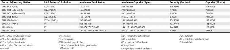
This section details the differences between the various sector-addressing methods and the limitations incurred by using them.
Prefixes for Decimal and Binary Multiples
Many readers are unfamiliar with the MiB (mebibyte), GiB (gibibyte), and so on designations I am using in this section and throughout the book. These are part of a standard designed to eliminate confusion between decimal- and binary-based multiples, especially in computer systems. Standard SI (system international or metric system) units are based on multiples of 10. This worked well for most things, but not for computers, which operate in a binary world where most numbers are based on powers of 2. This has resulted in different meanings being assigned to the same prefix—for example 1KB (kilobyte) could mean either 1,000 (103) bytes or 1,024 (210) bytes. To eliminate confusion, in December 1998 the International Electrotechnical Commission (IEC) approved as an international standard the prefix names and symbols for binary multiples used in data processing and transmission. Some of these prefixes are shown in Table 7.14.
Table 7.14 Standard Prefix Names and Symbols for Decimal and Binary Multiples

Under this standard terminology, an MB (megabyte) would be 1,000,000 bytes, whereas an MiB (mebibyte) would be 1,048,576 bytes.
Note
For more information on these industry-standard decimal and binary prefixes, check out the National Institute for Standards and Technology (NIST) website at http://physics.nist.gov/cuu/Units/prefixes.html.
BIOS Limitations
Motherboard ROM BIOSs have been updated throughout the years to support larger and larger drives. Table 7.15 shows the most important relative dates when drive capacity limits were changed.
Table 7.15 Dates of Changes to Drive Capacity Limitations in the ROM BIOS

These are when the limits were broken, such that BIOSs older than August 1994 are generally limited to drives of up to 528MB, whereas BIOSs older than January 1998 are generally limited to 8.4GB. Most BIOSs dated 1998 or newer support drives up to 137GB, and those dated September 2002 or newer should support drives larger than 137GB. These are only general guidelines, though; to accurately determine this for a specific system, you should check with your motherboard manufacturer. You can also use the System Information for Windows (SIW) utility from http://gtopala.com/, which will tell you the BIOS date from your system and specifically whether your system supports the Enhanced Disk Drive specification (which means drives over 8.4GB).
If your BIOS does not support EDD (drives over 8.4GB), the three possible solutions are as follows:
• Upgrade your motherboard BIOS to a 1998 or newer version that supports >8.4GB.
• Install a BIOS upgrade card, such as the UltraATA cards from www.siig.com.
• Install a software patch to add >8.4GB support.
Of these, the first one is the most desirable because it is usually free. Visit your motherboard manufacturer’s website to see whether it has any newer BIOSs available for your motherboard that will support large drives. If it doesn’t, the next best thing is to use a card such as one of the UltraATA cards from SIIG (www.siig.com). I almost never recommend the software-only solution because it merely installs a software patch in the boot sector area of the hard drive, which can result in numerous problems when booting from different drives, installing new drives, or recovering data.
CHS Versus LBA
There are two primary methods to address (or number) sectors on an ATA drive. The first method is called CHS (cylinder head sector) after the three respective coordinate numbers used to address each sector of the drive. The second method is called LBA (logical block address) and uses a single number to address each sector on a drive. CHS was derived from the physical way drives were constructed (and is how they work internally), whereas LBA evolved as a simpler and more logical way to number the sectors regardless of the internal physical construction.
![]() For more information on cylinders, heads, and sectors as they are used internally within the drive, see “Hard Disk Drive Operation,” p. 518 (Chapter 9, “Hard Disk Storage”).
For more information on cylinders, heads, and sectors as they are used internally within the drive, see “Hard Disk Drive Operation,” p. 518 (Chapter 9, “Hard Disk Storage”).
The process of reading a drive sequentially in CHS mode starts with cylinder 0, head 0, and sector 1 (which is the first sector on the disk). Next, all the remaining sectors on that first track are read; then the next head is selected; and then all the sectors on that track are read. This goes on until all the heads on the first cylinder are read. Then the next cylinder is selected, and the sequence starts again. Think of CHS as an odometer of sorts: The sector numbers must roll over before the head number can change, and the head numbers must roll over before the cylinder can change.
The process of reading a drive sequentially in LBA mode starts with sector 0, then 1, then 2, and so on. The first sector on the drive in CHS mode would be 0,0,1, and the same sector in LBA mode would be 0.
As an example, imagine a drive with one platter, two heads (both sides of the platter are used), two tracks on each platter (cylinders), and two sectors on each track. We would say the drive has two cylinders (tracks per side), two heads (sides), and two sectors per track. This would result in a total capacity of eight (2×2×2) sectors. Noting that cylinders and heads begin numbering from 0—whereas physical sectors on a track number from 1—using CHS addressing, we would say the first sector on the drive is cylinder 0, head 0, sector 1 (0,0,1); the second sector is 0,0,2; the third sector is 0,1,1; the fourth sector is 0,1,2; and so on until we get to the last sector, which would be 1,1,2.
Now imagine that we could take the eight sectors and—rather than refer directly to the physical cylinder, head, and sector—number the sectors in order from 0 to 7. Thus, if we wanted to address the fourth sector on the drive, we could reference it as sector 0,1,2 in CHS mode or as sector 3 in LBA mode. Table 7.16 shows the correspondence between CHS and LBA sector numbers for this eight-sector imaginary drive.
Table 7.16 CHS and LBA Sector Numbers for an Imaginary Drive with Two Cylinders, Two Heads, and Two Sectors per Track (Eight Sectors Total)

As you can see from this example, using LBA numbers is simpler and generally easier to handle; however, when the PC was first developed, all BIOS and ATA drive-level addressing was done using CHS addressing.
CHS/LBA and LBA/CHS Conversions
You can address the same sectors in either CHS or LBA mode. The conversion from CHS to LBA is always consistent in that for a given drive, a particular CHS address always converts to a given LBA address, and vice versa. The ATA-1 document specifies a simple formula that can be used to convert CHS parameters to LBA:
LBA = (((C×HPC) + H)×SPT) + S − 1
By reversing this formula, you can convert the other way—that is, from LBA back to CHS:
C = int (LBA / SPT / HPC)
H = int ((LBA / SPT) mod HPC)
S = (LBA mod SPT) + 1
For these formulas, the abbreviations are defined as follows:

Using these formulas, you can calculate the LBA for any given CHS address, and vice versa. Given a drive of 16,383 cylinders, 16 heads, and 63 sectors per track, Table 7.17 shows the equivalent CHS and LBA addresses.
Table 7.17 Equivalent CHS and LBA Sector Numbers for a Drive with 16,383 Cylinders, 16 Heads, and 63 Sectors per Track (16,514,064 Sectors Total)
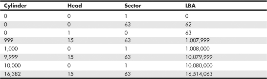
BIOS Commands Versus ATA Commands
In addition to the two methods of sector addressing (CHS or LBA), there are two levels of interface where sector addressing occurs. One interface is where the operating system talks to the BIOS (using driver commands); the other is where the BIOS talks to the drive (using ATA commands). The specific commands at these levels are different, but both support CHS and LBA modes. Figure 7.12 illustrates the two interface levels.
Figure 7.12 The relationship between BIOS and physical sector addressing. (In this figure, L-CHS stands for Logical CHS, and P-CHS stands for Physical CHS.)

When the operating system talks to the BIOS to read or write sectors, it issues commands via software interrupt (not the same as an IRQ) INT13h, which is how the BIOS subroutines for disk access are called. Various INT13h subfunctions allow sectors to be read or written using either CHS or LBA addressing. The BIOS routines then convert the BIOS commands into ATA hardware-level commands, which are sent over the bus I/O ports to the drive controller. Commands at the ATA hardware level can also use either CHS or LBA addressing, although the limitations are different. Whether your BIOS and drive use CHS or LBA addressing depends on the drive capacity, age of the BIOS and drive, BIOS Setup settings used, and operating system used.
CHS Limitations (the 528MB Barrier)
The original BIOS-based driver for hard disks is accessed via software interrupt 13h (13 hex) and offers functions for reading and writing drives at the sector level. Standard INT13h functions require that a particular sector be addressed by its cylinder, head, and sector location—otherwise known as CHS addressing. This interface is used by the operating system and low-level disk utilities to access the drive. IBM originally wrote the INT13h interface for the BIOS on the PC XT hard disk controller in 1983, and in 1984 the company incorporated it into the AT motherboard BIOS. This interface used numbers to define the particular cylinder, head, and sector being addressed. Table 7.18, which shows the standard INT13h BIOS CHS parameter limits, includes the maximum values for these numbers.
Table 7.18 INT13h BIOS CHS Parameter Limits

The concept of a maximum value given a number of digits is simple: If you had, for example, a hotel with two-digit decimal room numbers, you could have only 100 (102) rooms, numbered 0–99. The CHS numbers used by the standard BIOS INT13h interface are binary, and with a 10-bit number being used to count cylinders, you can have only 1,024 (210) maximum, numbered 0–1,023. Because the head is identified by an 8-bit number, the maximum number of heads is 256 (28), numbered 0–255. Finally, with sectors per track there is a minor difference. Sectors on a track are identified by a 6-bit number, which would normally allow a maximum of 64 (26) sectors; however, because sectors are numbered starting with 1 (instead of 0), the range is limited to 1–63, which means a total of 63 sectors per track is the maximum the BIOS can handle.
These BIOS limitations are true for all BIOS versions or programs that rely on CHS addressing. Using the maximum numbers possible for CHS at the BIOS level, you can address a drive with 1,024 cylinders, 256 heads, and 63 sectors per track. Because each sector is 512 bytes, the math works out as follows:
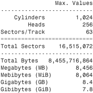
From these calculations, you can see that the maximum capacity drive addressable via the standard BIOS INT13h interface is about 8.4GB (where GB equals roughly 1 billion bytes), or 7.8GiB (where GiB means gigabinarybytes).
Unfortunately, the BIOS INT13h limits are not the only limitations that apply. Limits also exist in the ATA interface itself. The ATA CHS limits are shown in Table 7.19.
Table 7.19 Standard ATA CHS Parameter Limitations

As you can see, the ATA interface uses different-sized fields to store CHS values. Note that the ATA limits are higher than the BIOS limits for cylinders and sectors but lower than the BIOS limit for heads. The CHS limits for capacity according to the ATA-1 through ATA-5 specification are as follows:

When you combine the limitations of the BIOS and ATA CHS parameters, you end up with the situation shown in Table 7.20.
Table 7.20 Combined BIOS and ATA CHS Parameter Limits

As you can see, the lowest common denominator of the combined CHS limits results in maximum usable parameters of 1,024 cylinders, 16 heads, and 63 sectors, which results in a maximum drive capacity of 528MB. This became known as the 528MB barrier (also called the 504MiB barrier), and it affects virtually all PCs built in 1993 or earlier.
CHS Translation (Breaking the 528MB Barrier)
Having a barrier limiting drive capacity to 528MB or less wasn’t a problem when the largest drives available were smaller than that. But by 1994, drive technology had developed such that making drives larger than what the combined BIOS and ATA limitations could address was possible. Clearly a fix for the problem was needed.
Starting in 1993, the BIOS developer Phoenix Technologies began working on BIOS extensions to work around the combined CHS limits. In January of 1994, the company released the “BIOS Enhanced Disk Drive (EDD) Specification,” which was later republished by the T13 committee (also responsible for ATA) as “BIOS Enhanced Disk Drive Services (EDD).” The EDD documents detail several methods for circumventing the limitations of older BIOSs without causing compatibility problems with existing software. These include the following:
• BIOS INT13h extensions supporting 64-bit LBA
• Bit-shift geometric CHS translation
• LBA-assist geometric CHS translation
The method for dealing with the CHS problem was called translation because it enabled additional subroutines in the BIOS to translate CHS parameters from ATA maximums to BIOS maximums (and vice versa). In an effort to make its methods standard among the entire PC industry, Phoenix released the EDD document publicly and allowed the technology to be used free of charge, even among its competitors such as AMI and Award. The T13 committee in charge of ATA subsequently adopted the EDD standard and incorporated it into official ATA documents.
Starting in 1994, most BIOSs began implementing the Phoenix-designed CHS translation methods, which enabled drives up to the BIOS limit of 8.4GB to be supported. The fix involved what is termed parameter translation at the BIOS level, which adapted or translated the cylinder, head, and sector numbers to fit within the allowable BIOS parameters. There are two types of translation: One works via a technique called CHS bit-shift (usually called “Large” or “Extended CHS” in the BIOS Setup), and the other uses a technique called LBA-assist (usually called “LBA” in the BIOS Setup). These refer to the different mathematical methods of doing essentially the same thing: converting one set of CHS numbers to another.
CHS bit-shift translation manipulates the cylinder and head numbers but does not change the sector number. It begins with the physical (drive reported) cylinders and heads and, using some simple division and multiplication, comes up with altered numbers for the cylinders and heads. The sectors-per-track value is not translated and is passed unaltered. The term bit-shift is used because the division and multiplication math is actually done in the BIOS software by shifting bits in the CHS address.
With CHS bit-shift translation, the drive reported (physical) parameters are referred to as P-CHS, and the BIOS-altered logical parameters are referred to as L-CHS. After the settings are made in the BIOS Setup, L-CHS addresses are automatically translated to P-CHS at the BIOS level. This enables the operating system to send commands to the BIOS using L-CHS parameters, which the BIOS automatically converts to P-CHS when it talks to the drive using ATA commands. Table 7.21 shows the rules for calculating CHS bit-shift translation.
Table 7.21 CHS Bit-Shift Translation Rules

CHS bit-shift translation is based on dividing the physical cylinder count by a power of 2 to bring it under the 1,024 cylinder BIOS INT13h limit and then multiplying the heads by the same power of 2, leaving the sector count unchanged. The power of 2 used depends on the cylinder count, as indicated in Table 7.21.
Here is an example of CHS bit-shift translation:

This example shows a drive with 8,000 cylinders and 16 heads. The physical cylinder count is way above the BIOS limit of 1,024, so if CHS bit-shift translation is selected in the BIOS Setup, the BIOS then divides the cylinder count by 2, 4, 8, or 16 to bring it below 1,024. In this case, it would divide by 8, which results in a new logical cylinder count of 1,000—which is below the 1,024 maximum. Because the cylinder count is divided by 8, the head count is then multiplied by the same number, resulting in 128 logical heads, which is also below the limit the BIOS can handle.
So, although the drive reports having 8,000 cylinders and 16 heads, the BIOS and all software (including the operating system) instead see the drive as having 1,000 cylinders and 128 heads. Note that the 63 sectors/track figure is simply carried over without change. The result is that by using the logical parameters, the BIOS can see the entire 4.13GB drive and won’t be limited to just the first 528MB.
When you install a drive, you don’t have to perform the translation math to convert the cylinders and heads; the BIOS does that for you automatically. All you have to do is allow the BIOS to autodetect the P-CHS parameters and then enable the translation in the BIOS Setup. Selecting Large or ECHS translation in the BIOS Setup enables the CHS bit-shift. The BIOS does the rest of the work for you.
CHS bit-shift is a simple and fast (code-wise) scheme that can work with all drives, but unfortunately it can’t properly translate all theoretically possible drive geometries for drives under 8.4GB. To solve this, an addendum was added to the ATA-2 specification to specifically require drives to report certain ranges of geometries to allow bit-shift translation to work. Thus, all drives that conform to the ATA-2 specification (or higher) can be translated using this method.
The 2.1GB and 4.2GB Barriers
Some BIOSs incorrectly allocated only 12 bits for the P-CHS cylinder field, thereby allowing a maximum of 4,096 cylinders. Combined with the standard 16-head and 63-sector limits, this resulted in the inability to support any drives over 2.1GB in capacity. Fortunately, this BIOS defect affected only a limited number of systems with BIOS dates prior to about mid-1996.
Even so, some problems still existed with bit-shift translation. Because of the way DOS and Windows 9x/Me were written, they could not properly handle a drive with 256 heads. This was a problem for drives larger than 4.2GB because the CHS bit-shift translation rules typically resulted in 256 heads as a logical value, as seen in the following example:
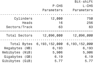
This scheme failed when you tried to install Windows 9x/Me (or DOS) on a drive larger than 4.2GB because the L-CHS parameters included 256 heads. Any BIOS that implemented this scheme essentially had a 4.2GB barrier, so installing a drive larger than that and selecting CHS bit-shift translation caused the drive to fail. Note that this was not a problem for Windows NT or later.
Note
It is interesting to note that the BIOS is not actually at fault here; the problem instead lies with the DOS/Win9x/Me file system code, which stores the sector-per-track number as an 8-bit value. The number 256 causes a problem because 256 equals 100000000b, which takes 9 bits to store. The value 255 (which equals 11111111b) is the largest value that can fit in an 8-bit binary register and is therefore the maximum number of heads those operating systems can support.
To solve this problem, CHS bit-shift translation was revised by adding a rule such that if the drive reported 16 heads and more than 8,192 cylinders (which would result in a 256-head translation), the P-CHS head value would be assumed to be 15 (instead of 16) and the P-CHS cylinder value would be multiplied by 16/15 to compensate. These adjusted cylinder and head values would then be translated. The following example shows the results:
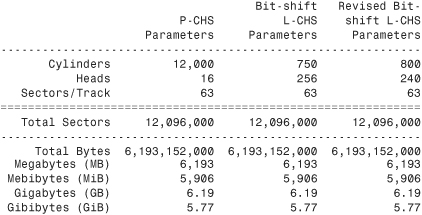
As you can see from this example, a drive with 12,000 cylinders and 16 heads translates to 750 cylinders and 256 heads using the standard CHS bit-shift scheme. The revised CHS bit-shift scheme rule does a double translation in this case, first changing the 16 heads to 15 and then multiplying the 12,000 cylinders by 16/15, resulting in 12,800 cylinders. Then, the new cylinder value is CHS bit-shift-translated (it is divided by 16), resulting in 800 logical cylinders. Likewise, the 15 heads are multiplied by 16, resulting in 240 logical heads. If the logical cylinder count calculates to over 1,024, it is truncated to 1,024. In this case, what started out as 12,000 cylinders and 16 heads P-CHS becomes 800 cylinders and 240 heads (instead of 750 cylinders and 256 heads) L-CHS, which works around the bug in the DOS/Win9x/Me operating systems.
So far, all my examples have been very clean—that is, the L-CHS parameters have calculated to the same capacity as the P-CHS parameters. Unfortunately, it doesn’t always work out that way. The following example shows a more typical example in the real world. Several 8.4GB drives from Maxtor, Quantum, Seagate, and others report 16,383 cylinders and 16 heads P-CHS. For those drives, the translations would work out as follows:
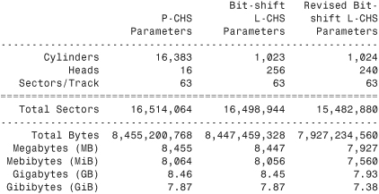
Note that the revised CHS bit-shift translation rules result in supporting only 7.93GB of the 8.46GB total on the drive. In fact, the parameters shown (with 240 heads) are the absolute maximum that revised CHS bit-shift supports. Fortunately, another translation mode is available that improves this situation.
LBA-Assist Translation
The LBA-assist translation method places no artificial limits on the reported drive geometries, but it works only on drives that support LBA addressing at the ATA interface level. Fortunately, though, virtually all ATA drives larger than 2GB support LBA. LBA-assist translation takes the CHS parameters the drive reports, multiplies them together to get a calculated LBA maximum value (total number of sectors), and then uses this calculated LBA number to derive the translated CHS parameters. Table 7.22 shows the rules for LBA-assist translation.
Table 7.22 LBA-Assist Translation Rules
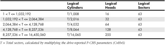
LBA-assist translation fixes the sectors at 63 no matter what and divides and multiplies the cylinders and heads by predetermined values depending on the total number of sectors. This results in a set of L-CHS parameters the operating system uses to communicate with the BIOS. The L-CHS numbers are then translated to LBA numbers at the ATA interface level. Because LBA mode is more flexible at translating, it should be used in most cases instead of CHS bit-shift.
Normally, both the CHS bit-shift and LBA-assist translations generate the same L-CHS geometry for a given drive. This should always be true if the drive reports 63 sectors per track and 4, 8, or 16 heads. In the following example, both translation schemes result in identical L-CHS values:

However, if the drive reports a value other than 63 sectors per track or has other than 4, 8, or 16 heads, LBA-assist translation does not result in the same parameters as CHS bit-shift translation. In the following example, different translations result:
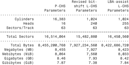
The LBA-assist translation supports 8.42GB, which is nearly 500MB more than the revised CHS bit-shift translation. More importantly, these translations are different, which can result in problems if you change translation modes with data on the drive. If you were to set up and format a drive using CHS bit-shift translation and then change to LBA-assist translation, the interpreted geometry could change and the drive could then become unreadable until it is repartitioned and reformatted (which would destroy all the data). Bottom line: After you select a translation method, don’t plan on changing it unless you have your data securely backed up.
Virtually all PC BIOSs since 1994 have translation capability in the BIOS Setup, and virtually all offer both translation modes as well as an option to disable translation entirely. If both CHS bit-shift and LBA-assist translation modes are offered, you should probably choose the LBA method of translation because it is the more efficient and flexible of the two. LBA-assist translation also gets around the 4.2GB operating system bug because it is designed to allow a maximum of 255 logical heads no matter what.
You usually can tell whether your BIOS supports translation by the capability to specify more than 1,024 cylinders in the BIOS Setup, although this can be misleading. The best clue is to look for the translation setting parameters in the ATA/IDE drive setup page in the BIOS Setup. See Chapter 5 for more information on how to enter the BIOS Setup on your system. If you see drive-related settings, such as LBA or ECHS (sometimes called Large or Extended), these are telltale signs of a BIOS with translation support. Most BIOSs with a date of 1994 or later include this capability, although some AMI BIOS versions from the mid-1990s locate the LBA setting on a screen different from the hard drive configuration screen. If your system currently does not support parameter translation, you might be able to get an upgrade from your motherboard manufacturer or install a BIOS upgrade card with this capability, such as the LBA Pro card from eSupport.com.
Table 7.23 summarizes the four ways today’s BIOSs can handle addressing sectors on the drive: Standard CHS (no translation), Extended CHS translation, LBA translation, and pure LBA addressing.
Table 7.23 Drive Sector Addressing Methods

Standard CHS has only one possible translation step internal to the drive. The drive’s actual physical geometry is completely invisible from the outside with all zoned recorded ATA drives today. The cylinders, heads, and sectors printed on the label for use in the BIOS Setup are purely logical geometry and do not represent the actual physical parameters. Standard CHS addressing is limited to 16 heads and 1,024 cylinders, which provides a limit of 504MiB (528MB).
This is often called “Normal” in the BIOS Setup and causes the BIOS to behave like an old-fashioned one without translation. Use this setting if your drive has fewer than 1,024 cylinders or if you want to use the drive with an operating system that doesn’t require translation.
ECHS, or “Large” in the BIOS Setup, is CHS bit-shift, and most BIOS from 1997 and later use the revised method (240 logical heads maximum).
LBA, as selected in the BIOS Setup, indicates LBA-assist translation, not pure LBA mode. This enables software to operate using L-CHS parameters while the BIOS talks to the drive in LBA mode.
The only way to select a pure LBA mode, from the OS to the BIOS as well as from the BIOS to the drive, is with a drive that is over 8.4GB. All drives over 137GB must be addressed via LBA at both the BIOS and drive levels, and most PC BIOSs automatically address any drive over 8.4GB in that manner, as well. In that case, no special BIOS Setup settings are necessary, other than setting the type to auto or autodetect.
Caution
A word of warning with these BIOS translation settings: If you have a drive 8.4GB or less in capacity and switch between Standard CHS, ECHS, or LBA, the BIOS can change the (translated) geometry. The same thing can happen if you transfer a disk that has been formatted on an old, non-LBA computer to a new one that uses LBA. This causes the logical CHS geometry seen by the operating system to change and the data to appear in the wrong location from where it actually is! This can cause you to lose access to your data if you are not careful. I always recommend recording the CMOS Setup screens associated with the hard disk configuration so you can properly match the setup of a drive to the settings to which it was originally set. This does not affect drives over 8.4GB because in those cases pure LBA is automatically selected.
The 8.4GB Barrier
Although CHS translation breaks the 528MB barrier, it runs into another barrier at 8.4GB. Supporting drives larger than 8.4GB requires leaving CHS behind and changing from CHS to LBA addressing at the BIOS level. The ATA interface had always supported LBA addressing, even in the original ATA-1 specification. One problem was that LBA support at the ATA level originally was optional, but the main problem was that there was no LBA support at the BIOS interface level. You could set LBA-assist translation in the BIOS Setup, but all that did was convert the drive LBA numbers to CHS numbers at the BIOS interface level.
Phoenix Technologies recognized that the BIOS interface needed to move from CHS to LBA early on and, beginning in 1994, published the “BIOS Enhanced Disk Drive Specification (EDD),” which addressed this problem with new extended INT13h BIOS services that worked with LBA rather than CHS addresses.
To ensure industrywide support and compatibility for these new BIOS functions, in 1996 Phoenix turned this document over to the International Committee on Information Technology Standards (INCITS) T13 technical committee for further enhancement and certification as a standard called the “BIOS Enhanced Disk Drive Specification (EDD).” Starting in 1998, most of the other BIOS manufacturers began installing EDD support in their BIOS, enabling BIOS-level LBA mode support for ATA drives larger than 8.4GB. Coincidentally (or not), this support arrived just in time because ATA drives of that size and larger became available that same year.
The EDD document describes new extended INT13h BIOS commands that allow LBA addressing up to 264 sectors, which results in a theoretical maximum capacity of more than 9.44ZB (zettabytes, or quadrillion bytes). That is the same as saying 9.44 trillion GB, which is 9.44×1021 bytes or, to be more precise, 9,444,732,965,739,290,427,392 bytes! I say theoretical capacity because even though by 1998 the BIOS could handle up to 264 sectors, ATA drives were still using only 28-bit addressing (228 sectors) at the ATA interface level. This limited an ATA drive to 268,435,456 sectors, which was a capacity of 137,438,953,472 bytes, or 137.44GB. Thus, the 8.4GB barrier had been broken, but another barrier remained at 137GB because of the 28-bit LBA addressing used in the ATA interface. The numbers work out as follows:

By using the new extended INT13h 64-bit LBA mode commands at the BIOS level, as well as the existing 28-bit LBA mode commands at the ATA level, no translation would be required and the LBA numbers would be passed unchanged. The combination of LBA at the BIOS and the ATA interface levels meant that the clumsy CHS addressing could finally die. This also means that when you install an ATA drive larger than 8.4GB in a PC that has an EDD-capable BIOS (1998 or newer), both the BIOS and the drive are automatically set to use LBA mode.
An interesting quirk is that to allow backward compatibility when you boot an older operating system that doesn’t support LBA mode addressing (DOS or the original release of Windows 95, for example), most drives larger than 8.4GB report 16,383 cylinders, 16 heads, and 63 sectors per track, which is 8.4GB. For example, this enables a 120GB drive to be seen as an 8.4GB drive by older BIOSs or operating systems. That sounds strange, but I guess having a 120GB drive being recognized as an 8.4GB is better than not having it work at all. If you did want to install a drive larger than 8.4GB into a system dated before 1998, the recommended solution is either a motherboard BIOS upgrade or an add-on BIOS card with EDD support.
The 137GB Barrier and Beyond
By 2001, the 137GB barrier had become a problem because 3 1/2″ hard drives were poised to breach that capacity level. The solution came in the form of ATA-6, which was being developed during that year. To enable the addressing of drives of greater capacity, ATA-6 upgraded the LBA functions from using 28-bit numbers to using larger 48-bit numbers.
The ATA-6 specification extends the LBA interface such that it can use 48-bit sector addressing. This means that the maximum capacity is increased to 248 (281,474,976,710,656) total sectors. Because each sector stores 512 bytes, this results in the maximum drive capacity shown here:
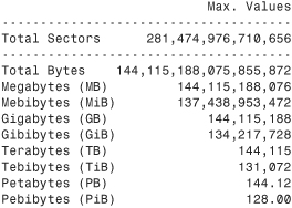
As you can see, the 48-bit LBA in ATA-6 allows a capacity of just over 144PB (petabytes = quadrillion bytes)!
Because the EDD BIOS functions use a 64-bit LBA number, they have a much larger limit:

Although the BIOS services use 64-bit LBA (allowing up to 264 sectors) for even greater capacity, the 144 petabyte ATA-6 limitation is the lowest common denominator that would apply. Still, that should hold us for some time to come.
Because hard disk drives have been doubling in capacity every 1.5 to 2 years (a corollary of Moore’s Law), I estimate that it will take us until sometime between the years 2031 and 2041 before we reach the 144PB barrier (assuming hard disk technology hasn’t been completely replaced by then). Similarly, I estimate that the 9.44ZB EDD BIOS barrier won’t be reached until between the years 2055 and 2073! Phoenix originally claimed that the EDD specification would hold us until 2020, but it seems they were being quite conservative.
The 137GB barrier proved a bit more complicated than previous barriers because, in addition to BIOS issues, operating system issues also had to be considered.
Internal ATA drives larger than 137GB require 48-bit LBA (logical block address) support. This support absolutely needs to be provided in the OS, but it can also be provided in the BIOS. It is best if both the OS and BIOS provide this support, but it can be made to work if only the OS has the support.
To have 48-bit LBA support in the OS requires one of the following:
• Windows XP with Service Pack 1 (SP1) or later.
• Windows 2000 with Service Pack 4 (SP4) or later.
• Windows 98/98SE/Me or NT 4.0 with the Intel Application Accelerator (IAA) loaded. This solution works only if your motherboard has an IAA-supported chipset. See www.intel.com/support/chipsets/IAA/ for more information.
To have 48-bit LBA support in the BIOS requires either of the following:
• A motherboard BIOS with 48-bit LBA support (most of those dated September 2002 or later)
• An ATA host adapter card with onboard BIOS that includes 48-bit LBA support
If your motherboard BIOS does not have the support and an update is not available from your motherboard manufacturer, you may be able to use a card. Promise Technology (www.promise.com) makes several different PCI cards with either PATA or SATA interfaces as well as an onboard BIOS that adds 48-bit LBA support.
Note that if you have both BIOS and OS support, you can simply install and use the drive like any other. If you have no BIOS support, but you do have OS support, portions of the drive past 137GB are not recognized or accessible until the OS is loaded. If you are installing the OS to a blank hard drive and booting from an original XP (pre-SP1) CD or earlier, you need to partition and install up to the first 137GB of the drive at installation time. After installing the OS and then the SP1 update, you can either partition the remainder of the drive using standard partitioning software or use a third-party partitioning program such as PartitionMagic or Partition Commander to resize the first partition to use the full drive. If you are booting from an XP SP1 or later CD, you can recognize and access the entire drive during the OS installation and partition the entire drive as a single partition greater than 137GB, if you want.
Finally, keep in mind that the original version of Windows XP, as well as Windows 2000/NT or Windows 95/98/Me, does not provide native support for ATA hard drives that are larger than 137GB. However, as indicated earlier, that can easily be solved by loading the appropriate service packs or the Intel Application Accelerator.
Operating System and Other Software Limitations
Note that if you use older software, including utilities, applications, or even operating systems that rely exclusively on CHS parameters, these items will see all drives over 8.4GB as 8.4GB only. You will need not only a newer BIOS, but also newer software designed to handle the direct LBA addressing to work with drives over 8.4GB.
Operating system limitations with respect to drives over 8.4GB are shown in Table 7.24.
Table 7.24 Operating System Limitations

In the case of operating systems that support drives over 8.4GB, the maximum drive size limitations are dependent on the BIOS and hard drive interface standard, not the OS. Instead, other limitations come into play for the volumes (partitions) and files that can be created and managed by the various operating systems. These limitations are dependent on not only the operating system involved, but also the file system that is used for the volume. Table 7.25 shows the minimum and maximum volume (partition) size and file size limitations of the various Windows operating systems. As noted in the previous section, the original version of XP, as well as Windows 2000/NT or Windows 95/98/Me, does not currently provide native support for ATA hard drives that are larger than 137GB. You will need to use Windows 7, Vista, or XP with Service Pack 1 or later installed to use an ATA drive over 137GB. This does not affect drives attached via USB, FireWire, SCSI, or other interfaces.
Table 7.25 Operating System Volume/File Size Limitations by File System

PATA/SATA RAID
RAID is an acronym for redundant array of independent (or inexpensive) disks and was designed to improve the fault tolerance and performance of computer storage systems. RAID was first developed at the University of California at Berkeley in 1987, and was designed so that a group of smaller, less expensive drives could be interconnected with special hardware and software to make them appear as a single larger drive to the system. By using multiple drives to act as one drive, increases in fault tolerance and performance could be realized.
Initially, RAID was conceived to simply enable all the individual drives in the array to work together as a single, larger drive with the combined storage space of all the individual drives added up, which is called a JBOD (Just a Bunch of Disks) configuration. Unfortunately, if you had four drives connected in a JBOD array acting as one drive, you would be four times more likely to experience a drive failure than if you used just a single larger drive. And because JBOD does not use striping, performance would be no better than a single drive either. To improve both reliability and performance, the Berkeley scientists proposed six levels (corresponding to different methods) of RAID. These levels provide varying emphasis on either fault tolerance (reliability), storage capacity, performance, or a combination of the three.
Although it no longer exists, an organization called the RAID Advisory Board (RAB) was formed in July 1992 to standardize, classify, and educate on the subject of RAID. The RAB developed specifications for RAID, a conformance program for the various RAID levels, and a classification program for RAID hardware.
The RAID Advisory Board defined seven standard RAID levels, called RAID 0–6. Most RAID controllers also implement a RAID 0+1 combination, which is usually called RAID 10. The levels are as follows:
• RAID Level 0: Striping—File data is written simultaneously to multiple drives in the array, which act as a single larger drive. This offers high read/write performance but very low reliability. Requires a minimum of two drives to implement.
• RAID Level 1: Mirroring—Data written to one drive is duplicated on another, providing excellent fault tolerance (if one drive fails, the other is used and no is data lost) but no real increase in performance as compared to a single drive. Requires a minimum of two drives to implement (same capacity as one drive).
• RAID Level 2: Bit-level ECC—Data is split one bit at a time across multiple drives, and error correction codes (ECCs) are written to other drives. This is intended for storage devices that do not incorporate ECC internally (all SCSI and ATA drives have internal ECC). It’s a standard that theoretically provides high data rates with good fault tolerance, but seven or more drives are required for greater than 50% efficiency, and no commercial RAID 2 controllers and/or drives without ECC are available.
• RAID Level 3: Striped with parity—Combines RAID Level 0 striping with an additional drive used for parity information. This RAID level is really an adaptation of RAID Level 0 that sacrifices some capacity, for the same number of drives. However, it also achieves a high level of data integrity or fault tolerance because data usually can be rebuilt if one drive fails. Requires a minimum of three drives to implement (two or more for data and one for parity).
• RAID Level 4: Blocked data with parity—Similar to RAID 3 except data is written in larger blocks to the independent drives, offering faster read performance with larger files. Requires a minimum of three drives to implement (two or more for data and one for parity).
• RAID Level 5: Blocked data with distributed parity—Similar to RAID 4 but offers improved performance by distributing the parity stripes over a series of hard drives. Requires a minimum of three drives to implement (two or more for data and one for parity).
• RAID Level 6: Blocked data with double distributed parity—Similar to RAID 5 except parity information is written twice using two different parity schemes to provide even better fault tolerance in case of multiple drive failures. Requires a minimum of four drives to implement (two or more for data and two for parity).
There are also nested RAID levels created by combining several forms of RAID. The most common are as follows:
• RAID Level 01: Mirrored stripes—Drives are first combined in striped RAID 0 sets, then the RAID 0 sets are mirrored in a RAID 1 configuration. A minimum of four drives is required, and the total number of drives must be an even number. Most PC implementations allow four drives only. The total usable storage capacity is equal to half of the number of drives in the array times the size of the lowest capacity drive. RAID 01 arrays can tolerate a single drive failure and some (but not all) combinations of multiple drive failures. Not generally recommended because RAID 10 offers more redundancy and performance.
• RAID Level 10: Striped mirrors—Drives are first combined in mirrored RAID 1 sets, then the RAID 1 sets are striped in a RAID 0 configuration. A minimum of four drives is required, and the total number of drives must be an even number. Most PC implementations allow four drives only. The total usable storage capacity is equal to half of the number of drives in the array times the size of the lowest capacity drive. RAID 10 arrays can tolerate a single drive failure and many (but not all) combinations of multiple drive failures. Similar to RAID 01, except with somewhat increased reliability because more combinations of multiple drive failures can be tolerated, and rebuilding an array after a failed drive is replaced is much faster and more efficient.
Additional custom or proprietary RAID levels exist that were not originally supported by the RAID Advisory Board. For example, from 1993 through 2004, “RAID 7” was a trademarked marketing term used to describe a proprietary RAID implementation released by the (now defunct) Storage Computer Corp.
When set up for maximum performance, arrays typically run RAID Level 0, which incorporates data striping. Unfortunately, RAID 0 also sacrifices reliability such that if any one drive fails, all data in the array is lost. The advantage is in extreme performance. With RAID 0, performance generally scales up with the number of drives you add in the array. For example, with four drives you won’t necessarily have four times the performance of a single drive, but many controllers can come close to that for sustained transfers. Some overhead is still involved in the controller performing the striping, and issues still exist with latency—that is, how long it takes to find the data—but performance will be higher than any single drive can normally achieve.
When set up for reliability, arrays generally run RAID Level 1, which is simple drive mirroring. All data written to one drive is written to the other. If one drive fails, the system can continue to work on the other drive. Unfortunately, this does not increase performance at all, and it also means you get to use only half of the available drive capacity. In other words, you must install two drives, but you get to use only one (the other is the mirror). However, in an era of high capacities and low drive prices, this is not a significant issue.
Combining performance with fault tolerance requires using one of the other RAID levels, such as RAID 5 or 10. For example, virtually all professional RAID controllers used in network file servers are designed to use RAID Level 5. Controllers that implement RAID Level 5 used to be very expensive, and RAID 5 requires that at least three drives must be connected, whereas RAID 10 requires four drives.
With four 500GB drives in a RAID 5 configuration, you would have 1.5TB of total storage, and you could withstand the failure of any single drive. After a drive failure, data could still be read from and written to the array. However, read/write performance would be exceptionally slow, and it would remain so until the drive was replaced and the array was rebuilt. The rebuild process could take a relatively long time, so if another drive failed before the rebuild completed, all data would be lost.
With four drives in a RAID 10 configuration, you would have only 1TB of total storage. However, you could withstand many cases of multiple drive failures. In addition, after a drive failure, data could still be read from and written to the array at full speed, with no noticeable loss in performance. In addition, once the failed drive is replaced, the rebuild process would go relatively quickly as compared to rebuilding a RAID 5 array. Because of the advantages of RAID 10, many are recommending it as an alternative to RAID 5 where maximum redundancy and performance are required.
A typical low-cost SATA RAID controller enables up to four, six, or eight drives to be attached, and you can run them in RAID Level 0, 1, 5, or 10 mode. Parallel ATA RAID cards are available, but most RAID cards have moved to Serial ATA, which doesn’t have the master/slave channel-sharing problems of Parallel ATA. Serial ATA RAID cards use a separate Serial ATA data channel (cable) for each drive, allowing maximum performance. Motherboard-based RAID controllers almost exclusively use SATA drives.
If you are considering a SATA RAID controller (or a motherboard with an integrated SATA RAID controller), here are some things to look for:
• RAID levels supported. (Most support 0, 1, 5, and 10. A lack of RAID 5 and/or RAID 10 support indicates a very low-end product.)
• Support for four, six, or eight drives.
• Support for 3Gbps or 6Gbps Serial ATA transfer rates.
• PCIe bus interface for best performance and future compatibility.
Some operating systems include software-based RAID capability; however, I don’t generally recommend using it because of performance issues. Normally if you want both performance and reliability, you should look for Serial ATA RAID controllers that support RAID Level 5 or 10.