
CHAPTER 3
Looking Inside Configuration Manager
This chapter explores some of the internals of System Center Configuration Manager Current Branch, also referred to as ConfigMgr. It describes the architecture and how ConfigMgr is designed, at both site and hierarchy levels. It dives into components that make up ConfigMgr and external components that ConfigMgr depends on—such as Windows Management Instrumentation (WMI), SQL Server, and Internet Information Services (IIS)—and reviews site-to-site and client-to-site communication methods.
This chapter includes an overview of WMI for those unfamiliar with this venerable technology, which powers Windows manageability. The chapter discusses the infrastructure architecture of WMI and the logical WMI object model, as well as how ConfigMgr leverages WMI to provide a stable automation and development interface for both clients and servers.
This chapter also explores the ConfigMgr database, discussing its data store and data access, as well as the types of client information stored and represented in the database. It introduces ConfigMgr’s status and state message systems and the role these play in relaying client and server status throughout the hierarchy.
This chapter discusses site-to-site replication for administrators and architects considering implementation of a hierarchy. It reviews the major replication methods provided by ConfigMgr to move data and content between sites. The last section covers Active Directory (AD) integration for those implementing Configuration Manager for the first time or planning to publish site data to AD.
Understanding the ConfigMgr Architecture
Configuration Manager is a highly scalable client management solution capable of supporting over a million client devices in a single hierarchy. Part of its capability to scale is due to its internal architecture. This chapter discusses ConfigMgr internals, providing information on how it operates and laying a foundation for further learning about ConfigMgr.
A combination of scalability of the various components, including sites, enables support of up to 175,000 clients in a standalone primary site or 150,000 clients in a primary site in a hierarchy. ConfigMgr therefore provides a distributed solution that scales depending on the function of each server. For example, a management point (MP), which is primarily a web service, scales up to 25,000 clients. A distribution point (DP) supports up to 4,000 client connections.
At its core, ConfigMgr is a three-tiered application:
![]() Web Server Tier: At the front of client and user connections are web servers that host websites and web services along with servers hosting content for applications and servers. These servers are the most numerous in a site, supporting large-scale environments.
Web Server Tier: At the front of client and user connections are web servers that host websites and web services along with servers hosting content for applications and servers. These servers are the most numerous in a site, supporting large-scale environments.
![]() Site Server Tier: The middle tier is the site server, which performs data processing for client data along with site and site system status data. The site server also manages the site systems within the site and performs and initiates intersite communication. The site server provides servicing for the site by installing and updating other site systems and the site itself.
Site Server Tier: The middle tier is the site server, which performs data processing for client data along with site and site system status data. The site server also manages the site systems within the site and performs and initiates intersite communication. The site server provides servicing for the site by installing and updating other site systems and the site itself.
![]() Site Database Tier: The third tier is the site database tier, hosted on Microsoft SQL Server. Since ConfigMgr 2012, the amount of processing performed by the database tier has steadily increased. The trend of the database tier tacking on more processing responsibilities continues in the latest version of ConfigMgr, with additional processing occurring in the site database rather than the site server or site systems.
Site Database Tier: The third tier is the site database tier, hosted on Microsoft SQL Server. Since ConfigMgr 2012, the amount of processing performed by the database tier has steadily increased. The trend of the database tier tacking on more processing responsibilities continues in the latest version of ConfigMgr, with additional processing occurring in the site database rather than the site server or site systems.
External Components to ConfigMgr
The following sections describe components that are crucial to the functioning of ConfigMgr. While these are not the only underlying components leveraged, they are the most crucial and are the ones you will come across most regularly.
The Role of WMI
WMI is used heavily throughout ConfigMgr. Used by the SMS provider on the server side, it provides a software development kit (SDK) interface to the site database. All administrative write and, optionally, read access to the site database is performed via WMI. This includes the ConfigMgr console itself. Every change made in the console is sent via remote procedure call (RPC) to the SMS provider. This WMI provider provides a stable platform to build applications and a gating mechanism to control access. ConfigMgr’s PowerShell cmdlets also leverage the SMS provider for access.
The site server uses WMI to install new and manage existing site systems. WMI determines whether prerequisites are met and installs bootstrap services that perform the actual installations of the site systems.
WMI is also used with various functions on the client side. It is used to store client information and configuration and to provide client-side automation and SDK support for client activities, along with older component object model (COM) interfaces. The ConfigMgr client uses WMI to gather hardware/software inventory, using built-in providers to gather the information required from the operating system (OS). Hardware inventory information is gathered directly from WMI.
Knowledge of WMI is crucial to troubleshooting various ConfigMgr processes on both the client and server sides. It is also useful if you are interested in scripting, automating, or developing applications to run on top of ConfigMgr.
The Role of IIS
IIS is a built-in component of Windows Server that enables Windows to host websites and services. ConfigMgr uses IIS to enable the platform to build its websites and services. ConfigMgr uses IIS to host a range of site system roles, including the following:
![]() Management Point
Management Point
![]() Distribution Point
Distribution Point
![]() Software Update Point
Software Update Point
![]() Application Catalog
Application Catalog
IIS is used to support .NET-based web services and ASP.NET websites (such as in the Application Catalog website and service), as well as Internet Server Application Programming Interface (ISAPI) filters and extensions (for example, in the MP). It also includes simpler file publishing capabilities for the DP. Understanding IIS is essential to troubleshooting client-side issues.
The Role of SQL Server
Microsoft SQL Server is the only database engine supported for hosting the ConfigMgr site database. Its database engine also provides the core components that enable ConfigMgr’s database replication service between sites. As discussed in the earlier section “Understanding ConfigMgr Architecture,” the site database of ConfigMgr has been performing an increasing amount of computation and processing of data since the 2012 release.
Even the ConfigMgr client contains a SQL Server Compact Edition (SQL Server CE) database for various internal functions. Microsoft does not document the database structure; ConfigMgr client automation should use the WMI Client SDK provider, discussed further in the section “The Configuration Manager Client WMI Namespace,” later in this chapter. Knowledge of SQL Server is useful for creating custom reports and troubleshooting advanced performance issues.
ConfigMgr Communication Methods
ConfigMgr uses a variety of communication methods between clients and servers. Understanding these methods can assist with troubleshooting as well as designing environments with complex network security requirements.
Server Message Block Protocol
Server Message Block (SMB), the protocol powering Windows Server file servers and file shares, has been used for file sharing since the early days of Windows. While the protocol has changed greatly over the years, these changes are not critical to ConfigMgr’s usage of SMB.
ConfigMgr uses SMB and file shares for content replication and intrasite communication, and clients may use it to access content. For additional information regarding client behavior and content replication, see the chapters that discuss software distribution functions: Chapter 11, “Creating and Managing Applications,” Chapter 12, “Creating and Using Deployment Types,” Chapter 13, “Creating and Managing Packages and Programs”, and Chapter 14, “Distributing and Deploying Applications and Packages.” Content includes application installation source files and OS images.
NOTE: THE SMB ROLE IN REPLICATION HAS CHANGED
ConfigMgr uses SMB to initialize intersite data replication, otherwise known as Data Replication Service (DRS). Prior to ConfigMgr 2012, SMB was used for all intersite client and site data replication. This is no longer the case, and it is now used only to jumpstart or reset database information. All subsequent replication occurs via DRS. See the next section for more information.
When installing site systems, you use SMB to place ConfigMgr site system installation files on the destination server to allow installation to start. This process uses administrative shares in Windows—that is, shares created automatically by Windows to enable easier remote administration of the Windows folder (%windir%) and the root folder of the hard drive. Push installation of ConfigMgr clients by the site server also uses SMB to place client installation binaries on Windows systems.
SMB also replicates information from remote site systems to the site server. The SMB connection is initiated by the site system server to the site server by default; you can override this in the site system properties in the console. Information replicated in this manner includes client-generated inventory and status and state messages received by the MP. The MP receives this information via its IIS web service and forwards it to the site server for processing.
Data Replication Service
DRS is a communication method first introduced in Configuration Manager 2012. It replaced the file-based replication methods previously used, removing the need to reprocess those files at each site in a hierarchy. All non-content replication between sites uses this method of replication.
DRS is both initialized and invoked by the site server. Replication occurs directly between the SQL Server database engine instances hosting the site database at each site and is built on a combination of SQL Server change tracking and the SQL Server Service Broker (SSB). Outside of invocation by the site server, all other work occurs inside the SQL Server database engine.
ConfigMgr Client Communications
Client communications in ConfigMgr primarily occur via HTTP or optionally HTTPS between the client and the MP, DP, and software update point (SUP). Several exceptions include clients accessing legacy package/program content from DPs and booting to Windows Preinstallation Environment (WinPE) via the Preboot eXecution Environment (PXE) protocol from a PXE-enabled DP.
The client does not communicate directly with the site server; it communicates with site system roles. You may install site system roles on the site server, which is common in smaller ConfigMgr environments. Note that except for client push installation, the client always initiates communication to the site system from a network point of view and never vice versa. This does not imply that ConfigMgr does not push software, updates, or general instructions to clients; it refers to the network traffic and how ports are opened.
While this may appear to be an architectural limitation, it is a key design component that enables ConfigMgr to scale to the level it does. Instead of the server consuming its own Transmission Control Protocol/Internet Protocol (TCP/IP) ports making outbound connections, clients connect to a single port and pull policy. That policy might be an instruction to “push” software or updates.
This method of communication includes client notifications, used to run an immediate policy retrieval or endpoint protection scan. Here the client establishes an outbound TCP connection to the server and attempts to keep that port open. The server can then reply on the same TCP session to instruct the client to immediately perform an operation. This means the server does not have to establish an outbound connection, and no open ports are required on the client. This is very similar to the architecture Exchange ActiveSync uses to push email to mobile phones, as well as the push notification infrastructures used by Apple and Google for their respective mobile platforms.
ConfigMgr’s Internal Components
A site server has several core internal components, each with a specific function. The most important ConfigMgr process is SMSExec, the SMS Executive, which is the main service on the site server. All major site server functions exist as threads underneath this process. The ConfigMgr console refers to these threads as components. A single component often consists of multiple threads responsible for initializing all types of intersite replication, processing of client information, processing of ConfigMgr site system information, and installation of site system roles.
Information and messaging within a site are routed through a series of folders and file shares called inboxes. Each inbox is located under <ConfigMgr install directory>inboxes and exists at each type of site, although some inboxes are dormant as the data they receive is not processed at that type of site. (For example, hardware inventory is not processed at the central administration site [CAS] or secondary sites.)
Another critical component is the SMS Agent Host, ccmexec.exe. This component or service, often known as the ConfigMgr client component, also serves critical functions on site system role holders such as the MP. These threads and their log files have names starting with MP_ (such as MP_Ddr.log or MP_Location.log). The MP runs primarily within IIS. Internally to IIS, it is hosted within a set of ISAPI components, which rely on ccmexec.exe threads to pull information from the site database. The components both respond to ConfigMgr client requests for policy and receive client data for eventual processing by the site server.
ccmexec.exe is also responsible for pushing client inventory, status, and state messages to the site server. You can override this in secure environments where it may be desirable to have the site server pull from a lower-trust Internet-facing MP than have that MP reach out to the site server.
Key Site Components
The following are some of the key site components and their functions:
![]() Configuration Manager Update: This standalone process and Windows service is responsible for handling upgrades of sites when initiated via the Updates and Servicing node of the console. It runs prerequisite checks and initiates setup.
Configuration Manager Update: This standalone process and Windows service is responsible for handling upgrades of sites when initiated via the Updates and Servicing node of the console. It runs prerequisite checks and initiates setup.
![]() Discovery Data Manager: This is a set of threads of SMSExec and is responsible for processing discovery information gathered by the various discovery methods available in ConfigMgr.
Discovery Data Manager: This is a set of threads of SMSExec and is responsible for processing discovery information gathered by the various discovery methods available in ConfigMgr.
![]() Hierarchy Manager: This thread of SMSExec services various functions. It ensures that information about the site is published to AD for clients and other sites in the hierarchy. It monitors for configuration errors that could block DRS. It also serves a critical role in replicating mobile device data from Intune (see the sidebar “A Replication Exception: Hybrid MDM with Microsoft Intune,” later in this chapter). The Hierarchy Manager is integral to the site and hierarchy upgrade process in ConfigMgr Current Branch, coordinating the upgrade process and packaging upgrade content binaries/files for replication through the hierarchy.
Hierarchy Manager: This thread of SMSExec services various functions. It ensures that information about the site is published to AD for clients and other sites in the hierarchy. It monitors for configuration errors that could block DRS. It also serves a critical role in replicating mobile device data from Intune (see the sidebar “A Replication Exception: Hybrid MDM with Microsoft Intune,” later in this chapter). The Hierarchy Manager is integral to the site and hierarchy upgrade process in ConfigMgr Current Branch, coordinating the upgrade process and packaging upgrade content binaries/files for replication through the hierarchy.
![]() Inventory Data Loader: This SMSExec thread is responsible for processing hardware inventory data from clients at primary site servers. It does not provide a direct function on the CAS or secondary sites.
Inventory Data Loader: This SMSExec thread is responsible for processing hardware inventory data from clients at primary site servers. It does not provide a direct function on the CAS or secondary sites.
![]() LAN Sender: LAN Sender is a set of threads of SMSExec. This component is confusingly named, as it is responsible for replication of information between sites—and sites often reside across WAN links. This naming has to do with legacy data protocols that are no longer supported, such as X.25 and ISDN. The LAN Sender uses SMB to transmit files to file shares hosted on a destination site, and it uses certain capabilities of the SMB protocol to make these copies capable of restarting and throttling.
LAN Sender: LAN Sender is a set of threads of SMSExec. This component is confusingly named, as it is responsible for replication of information between sites—and sites often reside across WAN links. This naming has to do with legacy data protocols that are no longer supported, such as X.25 and ISDN. The LAN Sender uses SMB to transmit files to file shares hosted on a destination site, and it uses certain capabilities of the SMB protocol to make these copies capable of restarting and throttling.
![]() Replication Configuration Monitor: This SMSExec thread is responsible for handling DRS replication between ConfigMgr sites. It handles both setup and repair of replication through initialization and regular initiation of replication in SQL Server itself by executing a stored procedure (
Replication Configuration Monitor: This SMSExec thread is responsible for handling DRS replication between ConfigMgr sites. It handles both setup and repair of replication through initialization and regular initiation of replication in SQL Server itself by executing a stored procedure (spDRSActivation). This component runs all on types of ConfigMgr sites to support DRS across the hierarchy. If this component or SMSExec is not running, the site cannot use DRS to replicate and is considered offline.
![]() Site Component Manager: This is hosted as a separate Windows process named SiteComp.exe and is responsible for servicing and updating within a site. While Configuration Manager Update updates the site by running setup in the background, Site Component Manager is responsible for updating SMSExec and all remote site systems and also for initial installation of those site systems. If this component is stopped, servicing operations cannot successfully complete, and no new remote site system roles can be installed or removed.
Site Component Manager: This is hosted as a separate Windows process named SiteComp.exe and is responsible for servicing and updating within a site. While Configuration Manager Update updates the site by running setup in the background, Site Component Manager is responsible for updating SMSExec and all remote site systems and also for initial installation of those site systems. If this component is stopped, servicing operations cannot successfully complete, and no new remote site system roles can be installed or removed.
This list is not exhaustive. For a more comprehensive list of components and their log files, see Appendix A, “Configuration Manager Log Files.”
ConfigMgr’s Use of Inboxes
Inboxes in ConfigMgr have a long history. Although still crucial, their criticality to the operation of a ConfigMgr site and its hierarchy has been reduced over the years. All client data passes through the inboxes located in the <ConfigMgr install directory>inboxes folder on the site server.
For example, say that the MP pulls information from the site database. Instead of writing information there, it pushes that information to one of the site server’s inboxes, based on the type of data. The major client information inboxes include authdataldr.box (hardware inventory), authsinv.box (software inventory), and authstatesys.box (state messages).
Discovery information processing also leverages inboxes. The various discovery methods write the discovery data records (DDR, or .ddr files) to authddm.box for processing by Data Discovery Manager, which inserts this information into the site database. This is then made available via the SMS provider over WMI and SQL Server views for Transact-SQL (T-SQL) access.
Inboxes also handle the flow of information for the purposes of content replication to support application management and operating system deployment (OSD).
Basically, all ConfigMgr client and server data touches an inbox at some point—to be forwarded (for processing), replicated (if content), or processed. The key design difference from ConfigMgr 2007 and earlier is that information now traverses inboxes as seldom as possible. Information and data is no longer processed and forwarded up the hierarchy for reprocessing at a higher level or down the hierarchy (in the case of content metadata and configuration information). The newer versions of ConfigMgr process information once and rely on DRS to move data between site databases.
A REPLICATION EXCEPTION: HYBRID MDM WITH MICROSOFT INTUNE
As discussed in this section, a key objective of the replication model is to process once and avoid forwarding information in files around the hierarchy. One exception is mobile device information from Intune, which takes a slightly different path in a hierarchy. Messages are synced from Intune via the service connection point (SCP). Chapter 16, “Integrating Intune Hybrid into Your Configuration Manager Environment,” and Chapter 17, “Managing Mobile Devices,” provide additional information on hybrid mobile device management (MDM). These messages are processed and then sent to their respective client data processing components (Data Discovery Manager [DDM], Data Loader, and StateSys) for processing into the site database, as with any other client data on a standalone primary site.
In a hierarchy, the SCP is installed at the CAS, and messages are sent to Hierarchy Manager for routing to the mobile device’s assigned site or the default mobile device site for the hierarchy (as defined in the Microsoft Intune Subscription properties). This is unusual because Hierarchy Manager does not normally route messages, even on a primary site, and because this client data is replicated down the hierarchy using file replication to transmit the data via SMB. As discussed in this section, client data has not been replicated via SMB and file replication since ConfigMgr 2012.
After the assigned or default mobile device (primary) site processes the client data, that information is replicated back to the CAS via DRS. This round trip is needed to have a single point of contact with Intune while continuing to offload the CAS from processing client data (as opposed to message routing).
A WMI Primer
WMI is Microsoft’s implementation of Web-Based Enterprise Management (WBEM), an industrywide initiative that provides a common technology for accessing management information across a heterogeneous enterprise estate. The group behind the standard is the Distributed Management Task Force (DMTF); for information on the DMTF and WBEM, see http://www.dmtf.org/standards/wbem. WBEM is a discovery, access, and manipulation methodology. The data model it provides access to is the Common Information Model (CIM). WMI implements CIM and provides access in accordance with WBEM.
NOTE: ABOUT THE WMI PRIMER
This section is intended for those who are unfamiliar with or want a better understanding of WMI. WMI has been part of Windows since Windows 2000 and continues to be available in Windows 10 and Windows Server 2016. If you are familiar with WMI, CIM, and WBEM in Windows, you can skip this section of the chapter.
This section also largely remains unchanged from the System Center 2012 Configuration Manager Unleashed (Sams Publishing) version of this book, as the information has not changed since that book was published in 2013.
Understanding the WMI Architecture
WMI provides a method to write programs and scripts that interact with local resources on Windows systems. It is frequently supplanted by PowerShell, which often leverages WMI to perform some of these functions. PowerShell is discussed further in the section “Interaction Between WMI and PowerShell,” later in this chapter, which discusses how ConfigMgr now allows access to its WMI interfaces via PowerShell.
WMI exposes managed resources through a COM API. Programs written in C/C++ can call these resources directly, or you can access them through intermediate layers with applications such as scripts, .NET code, Windows forms, or web forms. WMI presents a consistent and extensible object model to represent a wide variety of system, network, and other resources. Using WMI, which has been available since Windows 2000, ensures that the scripts you write will run on the widest variety of systems, although PowerShell is becoming equally ubiquitous for supported Microsoft operating systems. PowerShell has the added benefit of supporting Microsoft’s cloud services, and PowerShell itself can use WMI.
Following are examples of what you can do with WMI:
![]() Obtain a list of all accounts on a system and rename one of them
Obtain a list of all accounts on a system and rename one of them
![]() Get a list of running processes on the system
Get a list of running processes on the system
![]() Extract the network configuration of a system
Extract the network configuration of a system
Using an object model removes much of the complexity that is otherwise required to access and manipulate these resources. Examples of resources that are manageable through WMI include hardware devices, running processes, the Windows file system and Registry, applications, and databases.
You can use several methods to access WMI’s services and object model, including the following:
![]() Directly on the local machine
Directly on the local machine
![]() Remotely through a Distributed COM (DCOM) network connection
Remotely through a Distributed COM (DCOM) network connection
![]() Remotely using WinRM (Windows Remote Management)
Remotely using WinRM (Windows Remote Management)
![]() Remotely using PowerShell Remoting
Remotely using PowerShell Remoting
ConfigMgr also relies on DCOM access for remote access and calls WMI directly on systems running ConfigMgr code.
NOTE: WINDOWS REMOTE MANAGEMENT
While newer access methods such as WinRM exist, the original access method, DCOM, remains available. WinRM is Microsoft’s implementation of the DMTF’s WS-Man (Web Services Management) web services standard. WS-Man is a SOAP-based specification published by the DMTF. Simple Object Access Protocol (SOAP) is a standard for invoking objects remotely over an Hypertext Transfer Protocol (HTTP) or Hypertext Transfer Protocol over Secure Socket Layer (HTTPS) connection. Its main advantage is that it works across many existing network firewalls without additional configuration. For a complete description of WS-Man and related specifications, see http://www.dmtf.org/standards/wsman.
WMI supports requests from management applications to do the following:
![]() Retrieve or modify individual data items (properties) of managed objects
Retrieve or modify individual data items (properties) of managed objects
![]() Invoke actions (methods) supported by managed objects
Invoke actions (methods) supported by managed objects
![]() Execute queries against the data set of managed objects
Execute queries against the data set of managed objects
![]() Register to receive events from managed objects
Register to receive events from managed objects
WMI provides its own query language that allows you to query managed objects as data providers. WMI Query Language (WQL) is a subset of T-SQL with minor semantic changes. Unlike T-SQL, WQL does not provide statements for inserting, deleting, or updating data, and it does not support joins. WQL includes extensions that support WMI events and other features specific to WMI. ConfigMgr also has specific extensions to WQL that are available only in the ConfigMgr SMS provider. WQL is the basis for ConfigMgr queries in the administration console (because console connections use WMI to the SMS provider), whereas T-SQL is used for ConfigMgr reports, as reports run in SQL Server Reporting Services (SSRS). These languages are discussed in Chapter 20, “Configuration Manager Queries,” and Chapter 21, “Configuration Manager Reporting.”
An important advantage of WQL is that a WQL query can return WMI objects as well as specific properties. Because management applications such as the ConfigMgr console interact with WMI objects, WQL queries can return result sets that you can use within the ConfigMgr infrastructure. For example, ConfigMgr collection query rules are based on WQL queries. See https://docs.microsoft.com/sccm/develop/core/understand/extended-wmi-query-language for more information about WQL.
WMI handles requests from management applications as follows:
1. A management application submits a request to the WMI infrastructure, which passes the request to the appropriate provider. (The next section of this chapter describes WMI providers.)
2. The provider handles the interaction with the system resources and returns the resulting response to WMI.
3. WMI passes the response back to the calling application. This may be actual data about the resource or the result of a request operation.
Figure 3.1 shows this basic data flow in WMI.

FIGURE 3.1 Basic WMI data flow.
WMI Providers
WMI providers are similar to device drivers in that they know how to interact with a particular resource or set of resources. Like a device driver, a provider must implement certain interfaces that WMI expects every provider to have, along with some additional ones. Microsoft supplies several built-in providers as part of Windows, such as the Event Log provider and the BitLocker Drive Encryption provider. A list of Microsoft-supplied pro‑ viders is available at https://msdn.microsoft.com/library/aa394570.aspx. You will see providers implemented in the following ways:
![]() As dynamic link libraries (DLLs)
As dynamic link libraries (DLLs)
![]() As Windows processes and services
As Windows processes and services
The idea behind creating a provider is to relieve management applications and scripts from having to be coded specifically to use an interface or a method that a developer provides. WMI providers are translation layers between management/administrative tools and applications, and they enable applications to be easily integrated in an enterprise information technology (IT) operations environment.
Just as the WMI infrastructure serves management applications through a COM interface, providers act as COM servers to handle requests from the WMI infrastructure. When a provider loads, it registers its location and the classes, objects, properties, methods, and events it provides with WMI. WMI uses this information to route requests from management/administrative tools to the proper providers. Providers are then responsible for interacting with the underlying managed object, using whatever custom method the developer chose to implement.
About the WMI Infrastructure
Figure 3.2 displays the main logical components of the WMI infrastructure. The core is Common Information Model Object Manager (CIMOM), described in the “Inside the WMI Object Model” section, later in this chapter. CIMOM handles requests between management applications and WMI providers, communicating with management applications through the COM API, as described earlier, in the “Understanding the WMI Architecture” section. CIMOM also manages the WMI Repository, an on-disk database that WMI uses to store certain types of data. Dynamic data is pulled on demand from the provider when requested. Static data is stored in the WMI Repository. Providers can compile static information into this repository as part of registration; the information can be flagged for automatic recompilation.
Most files that WMI uses are stored by default on the file system in the %windir%system32wbem folder. The WMI Repository is a set of files located by default in %windir%System32wbem epository. The exact file system structure varies slightly depending on the Windows version.
The Winmgmt executable contains the WMI service components. The physical implementation of the WMI infrastructure varies depending on the version of Windows. Beginning with Windows Vista, Microsoft introduced several significant enhancements in WMI security and stability, including the ability to specify process isolation levels, security contexts, and resource limits for provider instances.

Configuration parameters for the WMI service are stored in the Windows Registry subtree HKEY_LOCAL_MACHINESoftwareMicrosoftWBEM. The keys and values in this section of the Registry specify WMI file locations, logging behavior, the list of installed providers, the default namespace for scripts, and other WMI options. You rarely need to edit these options directly. As with any changes to the Registry, use extreme caution as such changes can destabilize your system.
WMI also provides detailed logging of its activities. Prior to Windows Vista, log entries were written in plain text to files in the %windir%system32wbemlogs folder. Most of these logs no longer exist; Event Tracing for Windows (ETW) makes log data available to event data consumers, including the Event Log Service. Event tracing for WMI is not enabled by default. The “Managing WMI” section, later in this chapter, discusses logging and event tracing options for WMI and configuration of tracing for WMI.
Some WMI providers, such as the ConfigMgr provider, also log their activity. Appendix A discusses logging by the ConfigMgr WMI provider.
Inside the WMI Object Model
Understanding the WMI object model is essential for writing programs or scripts that interact with WMI. It is also helpful for ConfigMgr administrators who want a better understanding of ConfigMgr objects such as collections and client settings. CIM is the basis for the WMI object model. It defines a core model that provides the basic semantics for representing managed objects and describes several common models representing specific areas of management, such as systems, networks, and applications. Third parties develop extended models, which are platform-specific implementations of common classes. You can categorize the class definitions used to represent managed objects as follows:
![]() Core classes represent general constructs that are applicable to all areas of management. Core classes are part of the core model and are the basic building blocks from which other classes are developed.
Core classes represent general constructs that are applicable to all areas of management. Core classes are part of the core model and are the basic building blocks from which other classes are developed.
![]() Common classes represent specific types of managed objects and are generalized representations of a category of objects, such as a computer system or an application. These classes are not tied to a particular implementation or technology. The
Common classes represent specific types of managed objects and are generalized representations of a category of objects, such as a computer system or an application. These classes are not tied to a particular implementation or technology. The CIM_ManagedSystemElement class is the most basic and general class, and is at the root of the CIM class hierarchy.
![]() Extended classes are technology-specific extensions of common classes, such as a Win32 computer system or ConfigMgr.
Extended classes are technology-specific extensions of common classes, such as a Win32 computer system or ConfigMgr.
WMI classes support inheritance, meaning you can derive a new class from an existing class. The derived class is often referred to as a child, or subclass, of the original class. The child class has a set of attributes available from its parent class. Inheritance saves developers the effort of needing to create definitions for all class attributes from scratch. Developers of a child class can optionally override the definition of an inherited attribute with a different definition better suited to that class. A child class can also have additional attributes that are not inherited from the parent.
Typically, core and common classes are not used directly to represent managed objects; they are used as base classes from which other classes are derived. The “The Configuration Manager Client WMI Namespace” section of this chapter presents an example of how a class inherits attributes from its parent class.
A special type of WMI class is SystemClass. WMI uses system classes internally to support its operations. They represent things such as providers, WMI events, and inheritance metadata about WMI classes.
WMI classes support three types of attributes:
![]() Properties are characteristics of managed objects, such as the name of a computer system or the current value of a performance counter.
Properties are characteristics of managed objects, such as the name of a computer system or the current value of a performance counter.
![]() Methods are actions that a managed object can perform on your behalf. As an example, an object representing a Windows service may provide methods to start, stop, or restart the service.
Methods are actions that a managed object can perform on your behalf. As an example, an object representing a Windows service may provide methods to start, stop, or restart the service.
![]() Associations are links to a special type of WMI class, an association class, which represents a relationship between other objects.
Associations are links to a special type of WMI class, an association class, which represents a relationship between other objects.
You can also modify WMI classes, properties, and methods by using qualifiers. A qualifier on a class may designate it as abstract, meaning the class is used only to derive other classes, and no objects of that class will be created. Two important qualifiers designate data as static or dynamic:
![]() Static data: This data is supplied in the class or object definition and stored in the WMI Repository.
Static data: This data is supplied in the class or object definition and stored in the WMI Repository.
![]() Dynamic data: This data is accessed directly through the provider and represents live data on the system.
Dynamic data: This data is accessed directly through the provider and represents live data on the system.
The CIM specification includes a language for exchanging management information. Managed Object Format (MOF) provides a way to describe classes, instances, and other CIM constructs in textual form. In WMI, MOF files are included with providers to register the classes, properties, objects, and events they support with WMI. The information in the MOF files is compiled and stored to the WMI Repository. Examples of information in MOF format are included in the next section.
Namespaces organize WMI classes and other elements. A namespace is a container, much like a folder in a file system. Developers can add objects to existing namespaces or create new namespaces. The root namespace defines a hierarchy organizing the namespaces on a system. The “Managing WMI” section, later in this chapter, describes the WMI Control tool, which allows you to specify the default namespace for connections to WMI. Generally, the default namespace is rootCIMv2. This namespace defines most of the major classes for Windows management, and the next section looks at several classes in that namespace. Because ConfigMgr is all about Windows management, it is not surprising that it uses this namespace extensively. ConfigMgr also defines its own namespaces, discussed in the section “Configuration Manager and WMI.”
If you are familiar with relational databases such as SQL Server, you may find it useful to consider an analogy between WMI and a database system. Table 3.1 presents some corresponding WMI and database concepts. Table 3.1 is useful when you are attempting to correlate between SMS provider information in WMI and database views in SQL Server.
TABLE 3.1 Corresponding WMI and Database Concepts
WMI Concept |
Database Concept |
WMI infrastructure |
Database engine |
Namespace |
Database |
Class |
Table |
Instance |
Row |
Attribute |
Column |
This section discussed the major concepts of WMI and the CIM model, which are essential to understanding ConfigMgr WMI activity. To learn about other aspects of CIM, you might start with the tutorial at http://www.wbemsolutions.com/tutorials/CIM/index.html. The full CIM specification is at http://www.dmtf.org/standards/cim. Documentation for WMI is available at http://msdn.microsoft.com/library/aa394582.aspx.
Managing WMI
This section illustrates options available for configuring WMI; it is not a “how-to” guide for administering WMI. You should seldom need to modify the WMI settings directly during day-to-day ConfigMgr administration. However, understanding WMI’s options can help you understand its inner workings and functionality.
WMI Control is a graphical tool for managing the most important properties of the WMI infrastructure. Only members of the local Administrators group can use WMI Control. To run this tool, perform the following steps:
1. Launch the Computer Management MMC snap-in (compmgmt.msc). The exact procedure varies depending on the version of Windows you are running. Generally, you can right-click Computer or My Computer and choose Manage.
2. Expand the Services and Applications node in the console tree. For server operating systems, expand the Configuration node.
3. Right-click WMI Control and choose Properties.
WMI Control opens to the General tab. As shown in Figure 3.3, the properties on this tab confirm that you have successfully connected to WMI on the local machine, display some basic properties of your system, and specify the installed version of WMI.

FIGURE 3.3 The General tab for WMI Control shows a successful connection to WMI on the local machine.
TIP: ABOUT MANAGING WMI ON A REMOTE MACHINE
You can use the WMI Control tool to manage WMI locally or on a remote machine. To connect to WMI on a remote machine, follow the same procedure previously described in this section, with one additional step. Immediately after step 1, right-click the Computer Management node at the top of the tree, choose Connect to Another Computer, enter the name or IP address of the computer you want to manage, and click OK. After connecting to the remote machine, complete steps 2 and 3 of the procedure.
In addition to needing administrative privileges on the remote machine, you need appropriate DCOM permissions, described later in this section. In addition, DCOM network protocols must not be blocked on the remote machine or any intermediary devices.
You manage WMI security from the Security tab of the WMI Control tool. WMI uses standard Windows ACLs to secure each WMI namespace existing on a machine. A namespace, as described further in the “Inside the WMI Object Model” section of this chapter, is a container that holds other WMI elements. The tree structure in the Security tab shows the WMI namespaces (see Figure 3.4).

The namespace is the most granular level for applying ACLs in WMI. The process of setting security on WMI namespaces, and the technology behind it, is similar to the process of setting NT File System (NTFS) security. If you click a namespace to select it and click Security, you see a dialog box similar to the one displayed in Figure 3.5.

FIGURE 3.5 The WMI ACL entries for rootCIMv2, the main WMI namespace.
NOTE: ABOUT THE CONFIGMGR ADMINS GROUP
ConfigMgr automatically creates a local group named ConfigMgr Admins on each computer where you install the SMS provider, and it assigns appropriate WMI permissions to this group. All administrative users configured as part of role-based administration are added to this group automatically, as is the site server computer account. The name ConfigMgr Admins does not imply anything about the permissions related to role-based administration. If you grant your help desk staff members read-only access to the ConfigMgr console via role-based administration, they appear in the ConfigMgr Admins group. The ConfigMgr provider provides an additional security layer above the WMI namespace ACL supplied by Windows, down to the ConfigMgr object class and object instance level.
The dialog box in Figure 3.6 allows you to add security principals to the discretionary ACL (DACL) of the WMI namespace. The DACL specifies who can access the namespace and the type of access. Windows Vista enhancements to WMI, mentioned earlier in this chapter, in the section “Understanding the WMI Architecture,” include a system access control list (SACL) for WMI namespaces, which specifies the actions audited for each security principal.
TIP: ABOUT AUDITING
As with other auditing of object access in Windows, to audit access to WMI namespaces, you must enable the effective value of the Audit Object Access group policy setting. The Windows Security event log records the events specified in the auditing settings.
To specify auditing on a WMI namespace, follow these steps:
1. In the Security dialog box, shown in Figure 3.5, click Advanced.
2. In the Advanced Security Settings dialog box, click the Auditing tab.
3. Click Select a Principal and then enter the name of the user group or built-in security principal, as shown in Figure 3.6. Click OK.
4. Select Fail from the Type dropdown menu.
5. Click Show Advanced Permissions to display a list of specific types of events to audit.
6. In the Advanced dialog box, check the desired types of events from the selection of check boxes and click OK.

REAL WORLD: USING AUDITING TO TROUBLESHOOT WMI CONNECTIONS
You can use auditing as a troubleshooting tool in the following ways:
![]() You can audit for access failures to help determine if security problems are causing a WMI problem.
You can audit for access failures to help determine if security problems are causing a WMI problem.
![]() You can audit for access success to help determine whether there is a successful connection.
You can audit for access success to help determine whether there is a successful connection.
Be judicious in auditing; excessive auditing consumes unnecessary system resources and generates noise in the Security event log.
Figure 3.7 shows the entries to enable auditing for all access failures by members of the Domain Admins group.
The remaining tabs of the tool allow you to change the default namespace for WMI connections and provide several methods for backing up the WMI Repository. Windows system state backups also back up the repository. To enable tracing in Windows Vista and newer operating systems, enable logging and configure log options in the Windows Event Viewer.

Follow these steps to enable WMI Trace Logging in Windows Vista and later:
1. Open the Event Viewer (eventvwr.exe).
2. From the View menu, select Show Analytic and Debug Logs.
3. In the tree control, expand Applications and Service Logs -> Microsoft -> Windows -> WMI-Activity.
4. To enable the Trace event log, right-click Trace and select Enable Log from the context menu. Choose Log Properties from that menu to configure logging properties for WMI. You can now view, filter, and manage the WMI log from this node in the Event Viewer tree.
Enabling WMI activity tracing causes three different types of events to be generated in the WMI activity. These logs show the start, middle, and end of a single sequence (or WMI session). Following are the possible event IDs for these events:
![]() Event ID 1: This event shows the start of the WMI session. The key event fields are
Event ID 1: This event shows the start of the WMI session. The key event fields are User and Namespace. The User event field allows you to focus on only the operation sessions that you are looking for (as do the Operation and GroupOperationId fields if that user account is making multiple connections). The Namespace event field is important when similarly named classes are in two different namespaces, as the next event does not provide you with details of the namespace used.
![]() Event ID 2: This event shows the actual operations performed. There may be one or more Event ID 2 events generated, depending on the behavior of the application or script using WMI. These events contain
Event ID 2: This event shows the actual operations performed. There may be one or more Event ID 2 events generated, depending on the behavior of the application or script using WMI. These events contain ProviderName and Path fields. The Path field indicates the path to the WMI object called.
![]() Event ID 3: This event shows the end of the WMI session. The only event field that this event contains is
Event ID 3: This event shows the end of the WMI session. The only event field that this event contains is GroupOperationId, and it is used to indicate the session or sequence being closed.
Read more about WMI logging at http://msdn.microsoft.com/library/aa394564.aspx.
Note that User Account Control applies to privileged WMI operations. This can affect some scripts and command-line utilities. For a discussion of User Account Control and WMI, see http://msdn.microsoft.com/library/aa826699.aspx.
Additional command-line tools are available for managing WMI; see http://msdn.microsoft.com/library/aa827351.aspx.
Configuration Manager and WMI
ConfigMgr leverages WMI heavily. At its simplest, the client uses WMI to extract information about the hardware, OS, and installed software of the client machine. ConfigMgr also uses WMI to enable client agent and server-side functions. It is important for anyone working on ConfigMgr to understand WMI and its leverage by ConfigMgr. If you are already familiar with ConfigMgr and considering getting a deeper understanding of ConfigMgr’s internals, WMI is one of the best areas to focus on. If you are considering automating ConfigMgr via scripts and applications, the following sections are critical for understanding when and where to leverage WMI, as they show how ConfigMgr uses WMI on its servers and look at the client-side elements. They also take a brief look at how PowerShell and WMI interact in the context of ConfigMgr.
WMI on Configuration Manager Servers
The SMS provider is a WMI provider that exposes all the editable objects in the ConfigMgr site database as WMI-managed objects. The ConfigMgr console leverages the SMS provider to perform all administrative actions. Ancillary ConfigMgr tools such as Resource Explorer and Service Manager leverage the SMS provider to provide information. Chapter 8, “Using the Configuration Manager Console,” discusses the ConfigMgr console.
The SMS provider is typically deployed alongside the site server or site database server at each site, as discussed in Chapter 4, “Architecture Design Planning.” The provider also implements the ConfigMgr role-based administration (RBA) security model; ConfigMgr requires more granular administration controls than those provided by the WMI infrastructure. Chapter 23, “Security and Delegation in Configuration Manager,” covers RBA and security in detail.
The SMS provider has existed since Systems Management Server (SMS) was released. While the internals of the provider have changed, and object types have come and gone, its function remains unchanged. MSDN (Microsoft Developer Network) documentation sometimes refers to it as the SDK provider. The provider provides a translation layer between ConfigMgr console and the underlying SQL Server database, as shown in Figure 3.8. As SDKs tend to be stable to ensure backward compatibility and avoid breaking developer applications, the translation function of the SMS provider is critical. As Microsoft changes the database to support alterations to ConfigMgr, the SMS provider’s internal implementation also changes to talk to the altered components, keeping the public side of the interface intact. When entire features are deprecated and removed from ConfigMgr, the SMS provider removes the public interfaces.
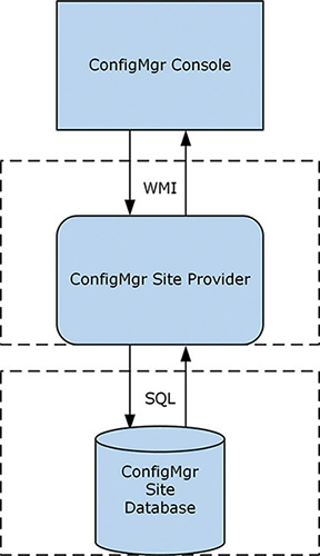
FIGURE 3.8 Diagram of the SMS provider architecture.
An important gating and control mechanism used by the SMS provider is a locking mechanism called Serialized Editing of Distributed Objects (SEDO), which helps ensure that objects are locked across the ConfigMgr hierarchy or within a site.
This is all handled for the user by the console and the SMS provider. When the same object is edited in one site while open in another site (even by the same user), an error is thrown by the console, allowing the user to either view the object as read-only or retry accessing the same object. Figure 3.9 shows an example of the error message.

SEDO: SERIALIZED EDITING OF DISTRIBUTED OBJECTS
The SEDO locking mechanism is built on the same architecture as ConfigMgr’s DRS (see the “Site-to-Site Replication” section, later in this chapter), removing the need for complex collision detection logic in a multi-master model like the ConfigMgr hierarchy model, as each primary site could in theory have the same object edited in parallel. There is no need for “last write wins” logic and/or overwritten objects to be saved with a temporary name. SEDO also saves ConfigMgr administrators from attempting to unwind these collisions.
These locks can be implicit or explicit in nature, depending on where the object is assigned. An implicit lock is always attempted. If the object is not assigned to the current site where the user is attempting to edit the object, an explicit lock request for the transfer of the lock from the assigned site must be requested.
Editing a SEDO-enabled object causes a SEDO message to be replicated immediately to the site where the object is assigned via DRS. If positive acknowledgement is not received from the assigned site, object editing cannot occur. This means editing can occur on the site where the object is assigned while replication is down—but not on other sites.
For more information about SEDO, see the ConfigMgr SDK at https://msdn.microsoft.com/library/hh949794.aspx.
This section uses ConfigMgr collections to illustrate how to walk through the capabilities provided by the SMS provider. (For information regarding collections, see Chapter 11 and Chapter 13.) It also walks through various SMS provider methods of extracting data. It assumes that these commands are local on the server hosting the SMS provider (usually the site server or the site database server) and that the site code of the ConfigMgr site is CAS. The commands are native PowerShell methods of interacting with WMI and not ConfigMgr-specific cmdlets, discussed in the “Interaction Between WMI and PowerShell” section, later in this chapter.
The following PowerShell command pulls all collection objects from the SMS provider:
Get-WmiObject -class SMS_Collection -namespace "rootSMSsite_CAS"
This command should return a number of collections. The following is an example of the output, showing a selection of important properties:
CollectionID                   : SMS00001
Comment                        : All Systems
LastChangeTime                 : 20160424145345.500000+***
LastMemberChangeTime           : 20160425182902.723000+***
LastRefreshTime                : 20160530110058.993000+***
MemberClassName                : SMS_CM_RES_COLL_SMS00001
MemberCount                    : 11
Name                           : All Systems
This output includes the MemberClassName property, which returns the class for all members of the collection. Use the following command to determine what devices are members of the All Systems collection:
Get-WmiObject -class SMS_CM_RES_COLL_SMS00001 -namespace "rootSMSsite_CAS"
This returns all instances of the SMS_CM_RES_COLL_SMS00001 class, which itself inherits the SMS_CollectionMember class (a generic definition of what any collection member should look like). There is one instance of the SMS_CM_RES_COLL_xxxxxxxx class per member of a collection. Each instance contains information about a member device or user (jointly referred to as a resource). Following are examples of properties that appear in the output:
DeviceOS                                 : Microsoft Windows NT Server 10.0
Domain                                   : ODYSSEY
IsClient                                 : False
Name                                     : PANTHEON
ResourceID                               : 2097152003
ResourceType                             : 5
Next, a ResourceID property is obtained. Every resource in the database has a ResourceID property that uniquely identifies it. You can use this property to find details about the client. These client details are intrinsic to that client and not related to its membership in one or more collections. The following command (which you can modify to match your client machine’s ResourceID) retrieves that information:
Get-WmiObject -class SMS_R_System -namespace "rootSMSsite_CAS" -filter
"ResourceID=2097152003"
Some of the object types introduced with ConfigMgr 2012 contain string properties that store eXtensible Markup Language (XML). While the role of the provider remains intact, using these XML properties allows for complex object models, such as the application model, and any objects based on compliance settings to be represented easily without massively extending the SMS provider object model. (Chapters 11 and 12 discuss the application model, and Chapter 10, “Managing Compliance,” covers compliance settings.) Storing this level of detail in distinct properties would mean a lot of inflexibility in regard to changes. The “Interaction Between WMI and PowerShell” section, later in this chapter, discusses how to read this information. You would write to these XML attributes by using .NET code (which is what the console does) published in the ConfigMgr SDK or PowerShell cmdlets specifically written to support these XML properties. You can see one of these XML elements by running the command in Listing 3.1 to return the XML definition of a ConfigMgr application object. (In this code, replace '7-Zip 15.14 (x64 edition)' with the name of an application in your environment.)
LISTING 3.1 Returning the XML Definition of a ConfigMgr Application Object
$app = Get-WmiObject -Class SMS_Application -Namespace "rootSMSsite_CAS"
   -Filter "LocalizedDisplayName='7-Zip 15.14 (x64 edition)'"
$app.Get()
$app.SDMPackageXML
The script returns a single string containing the XML definition of the application object. The $app variable shows very little specific information about the application, as all the critical information is stored in the SDMPackageXML property in XML.
The script has an intermediary step of calling $app.Get(). This is an important step, as the SDMPackageXML property is defined as a “lazy” property in WMI by the SMS provider. Marking a property lazy denotes that it is expensive to return relative to the other properties in an object. This may only be noticeable when a large number of instances of the class are returned. Because lazy properties are not returned using the default instantiation process for a class, these properties are returned null by default when queried. Using Get() tells WMI to return all lazy properties for a given instance of a class.
The Configuration Manager Client WMI Namespace
The ConfigMgr client heavily leverages WMI internally and externally. It creates its own additional classes in the rootCIMv2 namespace and creates its own distinct namespaces to support client activities. These namespaces begin with rootCCM. This namespace is actually shared between clients and the MP, as they share the same core process, ccmexec.exe. Underneath rootCCM are multiple additional namespaces supporting various client operations. As shown in Figure 3.10, you can see some of the additional namespaces via wbemtest (Windows Management Instrumentation Tester). Launch the wbemtest tool from any machine by running wbemtest.exe from the command prompt or the Windows Run dialog. Follow these steps to view the namespaces:
1. Run wbemtest.exe with elevated administrative rights.
2. Click Connect.
3. Under Namespace, enter rootCCM.
4. Click Connect.
5. Click Enum Instances.
6. Type __NAMESPACE and click OK.

TIP: TOOLS TO VIEW WMI
The remainder of this section uses wbemtest to interact with WMI and view various ConfigMgr namespaces. wbemtest was selected because it is universally available by default on all systems where WMI is installed (Windows 2000 and up). This makes the tool useful for troubleshooting issues on live production systems without the need to install other tools. The following are some other tools you might consider:
![]() WMI Explorer (PowerShell version): Written by Marc van Orsouw, http://powershell.org/wmi-explorer/
WMI Explorer (PowerShell version): Written by Marc van Orsouw, http://powershell.org/wmi-explorer/
![]() WMI Explorer (.NET version): https://wmie.codeplex.com/
WMI Explorer (.NET version): https://wmie.codeplex.com/
Some of the most interesting namespaces are rootCCMPolicy and its child namespaces rootCCMPolicyMachineactualconfig and rootCCMPolicy<User SID>actualconfig, which show machine and user policies targeted to that ConfigMgr agent. (Replace <User SID> with the Windows account security identifier [SID] for that user.) A policy is a combination of client settings, deployment, and schedules sent to the client by the ConfigMgr site, as discussed in the next section.
Other interesting namespaces are rootCCMSoftwareUpdates and rootCCMClientSDK. The SoftwareUpdates namespace is used to store information returned from the Windows Update Agent (WUA) API calls performed by the ConfigMgr agent as part of software update management. (See Chapter 15, “Managing Software Updates,” for information on software updates.) The ClientSDK namespace allows you to automate client-side activities. The “Automating the ConfigMgr Client via WMI” section, later in this chapter, discusses combining these two classes.
Obtaining Hardware Inventory Through WMI
The ConfigMgr client agent gathers hardware inventory data by querying WMI. The client agent settings determine what object classes were queried and sent to the server as the client’s inventory data. Most types of data gathered by hardware inventory are defined under the client agent settings in the ConfigMgr console. You can add or modify the total set of potential inventory collected by editing the default client agent settings or creating a custom client setting and deploying it to a collection of the systems from which you need to gather that information. Chapter 9, “Client Management,” describes client settings and inventory customizations through the ConfigMgr console.
NOTE: HARDWARE INVENTORY BY ANY OTHER NAME
Hardware inventory is a bit of a misnomer. While it does collect information about a client system’s hardware, it also collects far more information than just hardware. It also collects OS configuration information such as logical network configuration, services, features enabled on Windows Server, logged-in user information, and general OS information. It also collects information about installed applications and is the primary method of gathering Registry information from clients. Hardware inventory performs all these non-hardware-related operations because it is the method for gathering WMI information from clients. All the information listed is stored in WMI. For these resources, a more technically accurate though acronym-heavy and jargon-laced name for hardware inventory could be WMI inventory.
The Default Settings client settings ship out of the box with a number of preconfigured classes to gather. In some cases, you might require a custom data class. For example, you might need to gather information about an application or a specific OS configuration exposed in WMI. There may also be some Registry information you want to gather as a part of hardware inventory. (You can also determine how the Registry is configured via compliance settings; see Chapter 10.) In these cases, you import a .mof file into the default client settings or a custom client setting to gather this additional information.
To apply inventory settings from a custom .mof file, navigate to Administration -> Client Settings and either select Default Client Settings or create a Custom Client Device Settings object. On the Properties page, choose Hardware Inventory, click Set Classes, and click Import.
ConfigMgr clients download client settings as part of their machine policy retrieval cycle. Any changes are compiled and loaded into the WMI Repository. The ConfigMgr client stores its machine policy in the rootCCMPolicyMachineactualconfig WMI namespace. Use wbemtest to examine some of the inventory-related objects in this namespace. Follow these steps to launch wbemtest:
1 Run wbemtest.exe with elevated administrative rights.
2. Click Connect.
3. Under Namespace, as shown in Figure 3.11, enter rootCCMPolicyMachineactualconfig.
4. Click Connect.

To return a list of available classes in this namespace, click Enum Classes. You can double-click any of the returned classes to show their definitions. Then, to return all instances of a class, click Instances. Alternatively, if you know the name of the class you want to view, use Enum Instances instead of Enum Classes on the main page of wbemtest. Use either method to view the instances of the InventoryDataItem class.
InventoryDataItem is the class that represents inventory items defined in machine policy. At first, the list looks quite intimidating, with a bunch of globally unique identifiers (GUIDs) returned in a list. However, if you scroll to the right, you see the ItemClass property and much more human-readable information. Double-clicking the row for Win32_Service returns a list of all Windows services.
The Namespace and ItemClass properties tell the InventoryAgent thread of CCMExec.exe (the main ConfigMgr client process) what to inventory and its location. InventoryAgent is the component of the client responsible for gathering inventory. The Properties property contains a comma-separated list of properties to gather for each instance of Win32_Service under the rootCIMv2 namespace. These properties follow:
DisplayName, Name, PathName, ServiceType, StartMode, StartName, Status
Instances of the Win32_Service class have additional properties beyond those listed. To add additional properties to be gathered as part of hardware inventory, modify the client settings (either default or custom ones). To view these settings, open the ConfigMgr console and navigate to Administration -> Default Client Agent Settings -> Properties -> Hardware Inventory -> Set Classes. Classes that are checked are collected along with any checked properties. Figure 3.12 shows the properties for the Win32_Service class, which represents Windows background services.

FIGURE 3.12 The hardware inventory properties gathered for instances of Win32_Service on ConfigMgr clients.
Following is a list of the key ConfigMgr client namespaces:
![]()
ScanAgent
![]()
StateMsg
![]()
SoftwareUpdates
![]()
ContentTransferManager
![]()
DataTransferService
![]()
CIStore
![]()
ClientSDK
![]()
Scheduler
![]()
RebootManagement
![]()
Messaging
![]()
dcm
![]()
Policy
![]()
InvAgt
![]()
LocationServices
Automating the ConfigMgr Client via WMI
One of the most significant namespaces mentioned in the preceding section is the rootCCMClientSDK namespace. This namespace provides a wealth of classes, with information and methods that allow you to write client-side scripts or automation using WMI. While the other classes are useful for understanding some of the internal behaviors of the ConfigMgr client, the ClientSDK namespace has practical, everyday applications.
For example, if you want to automate software update management, you can use the CCM_SoftwareUpdatesManager and CCM_SoftwareUpdate classes to interact with and get the status of software updates, respectively. You can do the same for software distribution by using CCM_Program and CCM_ProgramManager and/or CCM_Application, CCM_ApplicationActions, and CCM_ApplicationPolicy, depending on the type of software distribution used.
A simple example of how to use ClientSDK is to get and set business hours defined on the client system. These business hours are designed to allow end users some self-service determination of when ConfigMgr client activity will occur (although ConfigMgr administrators can override this at will). Some customers want to modify or preconfigure these settings for end users. This section uses PowerShell to call out to WMI to get information about the configured business hours and change them.
You can start with getting the currently configured business hours by running the following command (run with elevated administrative rights), which invokes the GetBusinessHours method of the CCM_ClientUXSettings class:
Invoke-WmiMethod -Class CCM_ClientUXSettings -Namespace "rootccmclientsdk"
   -Name GetBusinessHours
This command returns something similar to the following (though internal WMI properties that start with __ and PSComputerName have been removed for readability):
EndTime          : 22
ReturnValue      : 0
StartTime        : 5
WorkingDays      : 62
These results show that on the test client, business hours start at 5 AM (05:00) and end at 10 PM (22:00). Figure 3.13 displays this in the Software Center.

FIGURE 3.13 The default Software Center business hours match what is found via the ClientSDK namespace.
You can alter this setting to set working hours to start at 6 AM (06:00) and end at 7 PM (19:00). Start by retrieving the order of the parameters for the SetBusinessHours method of the CCM_ClientUXSettings class. The Invoke-WmiMethod PowerShell cmdlet expects that input parameters are specified in a specific order. The following command finds the order:
([wmiclass]'rootccmclientsdk:CCM_ClientUXSettings').GetMethodParameters
  ('SetBusinessHours')
This command returns something similar to the following (though internal WMI properties that start with __ and PSComputerName have been removed for readability):
EndTime          :
StartTime        :
WorkingDays      :
This shows that the order of the input parameters is EndTime, StartTime, and WorkingDays. Leave WorkingDays as it is (on the test client, it is 62, which maps to Mon–Tue–Wed–Thu–Fri). The following command allows you to invoke the SetBusinessHours method to alter the client’s business hours to 6 AM to 7 PM (06:00 to 19:00):
Invoke-WmiMethod -Class CCM_ClientUXSettings -Namespace "rootccmclientsdk"
   -Name SetBusinessHours -ArgumentList 19,6,62
You should get a result with a ReturnValue property set to zero (success). Now if you re-invoke GetBusinessHours, you get the following (though internal WMI properties that start with __ and PSComputerName have been removed for readability):
EndTime          : 19
ReturnValue      : 0
StartTime        : 6
WorkingDays      : 62
This matches Figure 3.14, which shows the new Software Center business hours settings.

FIGURE 3.14 The changed Software Center business hours after invoking the SetBusinessHours method.
Further information on the ClientSDK namespace is available in the ConfigMgr SDK in MSDN at https://msdn.microsoft.com/library/jj874139.aspx.
Interaction Between WMI and PowerShell
ConfigMgr has been based on WMI since its SMS days. For IT pros, this meant using Visual Basic scripts to automate tedious ConfigMgr tasks or using alternative scripting languages such as Perl. With the advent of PowerShell, which has become the standard scripting interface across Microsoft’s products, ConfigMgr administrators faced a gap compared to the proliferation of PowerShell skills across other teams in their organizations. PowerShell can make calls to WMI, meaning it has always been possible to use PowerShell to make calls to the SMS provider to both get and set (read/write) data. However, it was not always straightforward, given some of the more niche capabilities of WMI that the SMS provider leverages. In addition, there were few samples of this from Microsoft, although the community generated many good examples and samples.
Starting with ConfigMgr Current Branch version 1610, Microsoft has integrated PowerShell cmdlets into each release of ConfigMgr Current Branch. This negates the need to update the cmdlet module in addition to the console with each release. The latest information on the changes in each release can be found at https://docs.microsoft.com/powershell/sccm/overview.
One of the most important capabilities of the PowerShell module is that it introduces the ability to handle XML data types. ConfigMgr 2012 and later rely heavily on XML data types of compliance settings and related objects (software update, application management, and MDM). When these features are accessed via WMI, critical data is stored only in string WMI properties as XML. Reading this data is therefore challenging if you do not have knowledge of the data types, and writing becomes a dangerous operation to codify.
The ConfigMgr console achieves reading and writing of these XML documents via specific .NET libraries, documented in the ConfigMgr SDK. The PowerShell module requires the console to be installed so it can leverage the full suite of the .NET libraries to enable access to the SMS provider.
Compare the results of this PowerShell WMI cmdlet:
$app = Get-WmiObject -Namespace "rootsmssite_CAS" -Class SMS_Application
  -Filter "LocalizedDisplayName='Microsoft Outlook'"
Get-WmiObject -Namespace "rootsmssite_CAS" -Class SMS_DeploymentType
  -Filter ("AppModelName='" + $app.ModelName + "'")
with the results of this ConfigMgr PowerShell module cmdlet:
Get-CMDeploymentType -ApplicationName "<application name>"
The ConfigMgr PowerShell method is simpler, and you can also easily create deployment types by using Add-CMDeploymentType, whereas with WMI, you would need to build the XML in PowerShell or use PowerShell to call out to .NET, neither of which is a trivial task.
Inside the ConfigMgr Database
The ConfigMgr database stores all information about your ConfigMgr environment. This includes information about all agent-managed clients, Intune-managed mobile devices, site information, and discovery information. ConfigMgr supports only Microsoft SQL Server for hosting its database. By default, the database is named CM_ followed by the three-digit alphanumeric code for the ConfigMgr site in question.
Microsoft does not publish the database schema, as it can change without notice. Instead, Microsoft publishes information about the views and works to keep these views static between releases.
ConfigMgr Tables and Views
ConfigMgr’s database, like any other SQL Server database, contains information in a series of tables. Tables store information in two dimensions. One dimension of each table is defined by a set of columns. The other dimension is the rows or instances of the column sets.
As discussed in the previous section, Microsoft does not publicly document these tables. SQL Server provides another method of accessing information: using views. Consider views as virtual tables; a view is essentially a query exposing data from one or more tables. Microsoft publishes information about these views, and every built-in report in ConfigMgr is based on these views. The idea is not to isolate information from customers but rather to provide a stable platform for them to build reports and solutions. In the event that a table needs to be changed, Microsoft modifies the associated view to ensure that existing reports are not impacted. Chapter 21 provides more details on views and their usage along with other methods of reporting on ConfigMgr data.
NOTE: THE DYNAMIC NATURE OF THE CONFIGMGR DATABASE SCHEMA
The ConfigMgr schema is not documented, and it is subject to change with each release and also changes dynamically. Specifically, when you modify the data collected by discovery or inventory methods in ConfigMgr, the tables and views supporting discovery and inventory are modified automatically.
In the case of discovery, adding an attribute to a discovery method causes DDM to request the addition of a column to the underlying table for the resource (user or system) where the attribute is added. An example of this is adding an AD attribute to AD User Discovery or AD System Discovery in the console, which triggers the change on the process of the .ddr files by the DDM thread of the SMSExec process.
Modifying hardware inventory by collecting an additional WMI property or class causes changes in the tables supporting hardware inventory. Specifically, when the resulting .mif files are processed by Data Loader (the dataldr thread of SMSExec), one of two changes occurs. In the case of an additional property to an existing class, an additional column is added to the table holding instances of this class across clients, along with the table’s corresponding view. In the case of an additional WMI class being inventoried, an additional table and view are created.
Using SQL Server Management Studio
While most day-to-day ConfigMgr administration does not require accessing the site database, it is useful to know how to view information in the database. This can be helpful for support purposes and to quickly view information to support creating scripts (or other applications) or reporting. The following steps walk you through using SQL Server Management Studio, the SQL Server administrative interface. (See Chapter 21 for additional information on SQL Server Management Studio and the basics of T-SQL.)
To access the ConfigMgr views, perform the following steps:
1. Open SQL Server Management Studio by going to Start -> All Programs -> Microsoft SQL Server <version> -> SQL Server Management Studio.
2. After the console launches, enter the name of the SQL Server hosting the ConfigMgr site database.
3. After the connection completes, expand the <servername>databaseCM_<site code>views in the left-hand pane.
CAUTION: DO NOT CHANGE THE CONFIGMGR DATABASE
Microsoft does not support modifying the ConfigMgr site database, as doing so can cause unpredictable results and may affect the stability of the database’s site or even the hierarchy. Do not add, delete, or change objects in the database. Do not modify any data stored in any objects.
Microsoft Support professionals may request a change as part of a workaround or resolution to an issue, based on guidance from the ConfigMgr development team. Prior to making any changes, under guidance from Microsoft Support, the authors recommend always making a backup of the database (and confirm restorability).
Exploring the ConfigMgr Database
The following sections discuss how to view various types of data stored in the ConfigMgr database and show how this information appears in the sample environment used by this book. Chapter 21 includes a more comprehensive list of various object types and their corresponding views in the database.
Collections
Let’s start with one of the most critical ConfigMgr object types, the collection. (You glimpsed the use of collections with WMI in the “WMI on Configuration Manager Servers” section, earlier in this chapter.) In WMI, the ConfigMgr collection class is named SMS_Collection. In the site database, the view is very similarly named v_Collection, with the only change in naming being the move from SMS_ to v_. (This is covered further in the tip “Finding Other Views in the Database Schema Dynamically,” later in this chapter.) Figure 3.15 shows what v_Collection looks like. These columns match up nicely with the information you see when looking at SMS_Collection properties. You will see this pattern repeated frequently when moving between WMI and SQL.

FIGURE 3.15 v_Collection displayed using SQL Server Management Studio.
Figure 3.15 shows the CollectionID column as the unique (within the hierarchy) identifier for the collection. This is an important column when you want to link v_Collection to other views. You can also use this column with v_FullCollectionMembership to return devices or users in a given collection.
In addition, there are views created dynamically for each collection, named v_CM_RES_COLL_<collectionID>. For example, the view v_CM_RES_COLL_SMS00001 represents the default All Systems collection. As you create collections, more of these dynamic collections are created, each containing the member users or devices of that collection. This is useful when you are writing scripts or queries that need to access collection members and you need to use a specific collection every time. If you need to parameterize, or take the collection as input to the script/query you are writing, using v_FullCollectionMembership provides a better view.
Hardware Inventory
Hardware inventory views are interesting for several reasons. They follow a similar naming standard as collection views, where their WMI name (for example, SMS_G_System_PC_BIOS) has the SMS_G_System turned into v_GS (for example, v_GS_PC_BIOS). These views are also dynamically created and modified in several different scenarios. When processing hardware inventory for a newly added class, when adding a new property, or when the value of property is too long to fit into the existing column for the property in the site database, SMSExec automatically alters the table schema to fit the new incoming data. The corresponding view to that table is created or modified to accommodate the newly defined table definition.
Client Settings
Client settings are also found in the site database views and stored in v_SMSMClientAgentConfig_Base. Note that settings are quite often stored in XML-typed columns in the client settings view. This can make reporting or reading a query difficult in some instances. SQL Server natively supports handling XML data in T-SQL queries; Listing 3.2 shows an example of how to extract the endpoint protection definition update fallback source and order it using the T-SQL CROSS APPLY command.
LISTING 3.2 Extracting the Endpoint Protection Definition Update Fallback Source
SELECT AMSettings.Name, CliSettings.PropertyName,

   AMSettingsValue.FallbackSource.value('.', 'nvarchar(max)') AS 'FallbackSource'
FROM vSMS_AntimalwareSettings AS AMSettings

JOIN vSMS_ClientAgentConfig_Base AS CliSettings
ON AMSettings.ID = CliSettings.SettingsID

CROSS APPLY CliSettings.XmlValue.nodes('/StringArrayXML/Value') AS
AMSettingsValue(FallbackSource)

WHERE CliSettings.PropertyName = 'FallbackOrder'
This should return something similar to the information shown in Figure 3.16, with readable information for each endpoint protection policy defining the fallback order to use.

FIGURE 3.16 Query results showing how XML data is presented when handled via T-SQL.
TIP: FINDING OTHER VIEWS IN THE DATABASE SCHEMA DYNAMICALLY
There are multiple ways to find additional views and methods of extracting data from the site database:
![]() You can look at a built-in report that contains the information you are looking for or as a start on that information.
You can look at a built-in report that contains the information you are looking for or as a start on that information.
![]() You can use the
You can use the v_SchemaViews view, which contains a list of all other views defined in the site database and their general types, including Status, Inventory, and Inventory History. A key type is the Schema type, which defines the other helper views besides v_SchemaView. Looking at these views is useful as the views sometimes contain late-breaking views that have not yet been documented elsewhere. Use the following query to find them:
SELECT [Type],[ViewName] FROM [v_SchemaViews] WHERE [Type]='Schema'
![]() You can trawl the definitions of views looking for particular column names. This can be useful when you have a certain column that you want to join to another view but do not know what other views contain the same column that might be useful as joins. This method is the most complex and relies on querying the SQL Server system views to extract information about the schema. Such a query can also be modified to search for other objects.
You can trawl the definitions of views looking for particular column names. This can be useful when you have a certain column that you want to join to another view but do not know what other views contain the same column that might be useful as joins. This method is the most complex and relies on querying the SQL Server system views to extract information about the schema. Such a query can also be modified to search for other objects.
In the sample query shown in Listing 3.3, you can replace ResourceID to search for a different string, but be sure to retain the % symbols.
LISTING 3.3 Searching the Definitions of All Database Views for a Particular String
DECLARE @varObjectToSearchFor varchar(max)

SET @varObjectToSearchFor = '%ResourceID%'

SELECT
udf.name AS [Name]

FROM
sys.objects AS udf
LEFT OUTER JOIN sys.sql_modules AS smudf ON smudf.object_id = udf.object_id
LEFT OUTER JOIN sys.system_sql_modules AS ssmudf ON ssmudf.object_id = udf.object_id
WHERE
(udf.type = 'V') AND
(ssmudf.definition LIKE @varObjectToSearchFor OR smudf.definition
   LIKE @varObjectToSearchFor)

ORDER BY
[Name] ASC
Status and State Messages Overview
The following sections discuss status and state messages and their use within ConfigMgr. Status messages have existed in ConfigMgr since SMS 2.0. State messages are a newer concept, introduced with ConfigMgr 2007, and their usage has expanded since that time.
Using Status Messages
A status message represents an event and is similar to messages in the Windows Event Log. Each status message type has a defined message template and variables populated by the component generating the message. These messages are not stateful, in that they do not designate the particular state of a client or a client operation or deployment. However, each process (such as legacy software distribution via packages and programs, discussed in Chapters 13 and 14) has a process defined in code that it goes through and certain status messages it generates. From that defined process, it is possible to infer statefulness. For example, if a package-based software distribution deployment goes through six steps, each with its own message, you can infer that if you see the message from step 6 that it has completed the process. The issue is that if a seventh step is added in an update to ConfigMgr, reports and processes would need to be rewritten to support the new definition of the final message in the process.
Conversely, status messages are useful for task sequences in OSD. Because a task sequence (TS) is a custom set of steps defined by an administrator, generating a hard-coded set of state messages would not be useful as these messages could only define known stages (such as starting, processing, and ending a TS). Status messages are generated for each step in the TS during task sequence execution. (For more information about OSD, see Chapter 22, “Operating System Deployment.”)
Status messages are also useful for picking up specific events from site servers and site systems for methods of eventing as data from clients is processed and internal processes occur. For example, if the Data Loader (DataLdr) is unable to process a delta inventory because it has yet to receive a full inventory (usually because a client was deleted manually from the console), it generates a status message to reflect that. If the Site Component Manager (SiteComp) cannot install or reinstall a site system role, it generates a status message for each failed attempt.
Client status messages are sent via the MP to the primary site server for processing. Both client and server status messages are written to the statmgr.box inbox for processing and are processed by the Status Manager component of SMSExec on the site server and inserted into the site database.
How State Messages Work
In contrast to status messages, state messages (as their name implies) are stateful. Each state message refers to a specific activity, compliance item, or operation. These messages have distinctly defined topics that they relate to (for example, application management). Each topic has multiple corresponding state message IDs that define the state for the instance of the topic.
For example, a certain topic type defines some state messages as relating to application management. Within that topic type are state message IDs that correlate to the various states of an application deployment, including Success, In Progress, Unknown, Requirements Not Met, or Error. The instance of the topic type in this case is an application deployment to a user or device. Each message reflects a state of the deployment and overwrites the last reported state. Conceptually, an application deployment may go from Unknown to In Progress and then to either Success or Error, depending on whether the application installer succeeded or failed.
State messages are used primarily to support client operations and reduce the need for repeated messages and are generally less noisy than status messages. For example, if an application repeatedly fails, it may simply stay in the Error state unless the specific type of error changes. Contrast this with status messages, which are generated for each attempt, with potentially more than one status message per attempt. A client also maintains a list of the various activities and deployments for which it has sent a state message; wherever possible, it attempts to send delta state messages to reduce the load on the site infrastructure.
State messages are sent via the MP to the primary site server for processing. They are written to the authstatesys.box inboxes for processing and are in turn processed by the State System component of SMSExec on the site server and inserted into the site database.
Site-to-Site Replication
The following sections cover the two primary methods of site-to-site replication in ConfigMgr: database replication (handled by DRS) and content replication (or file replication). These replication methods have been the cornerstone of ConfigMgr since the 2012 release.
About Configuration Manager Database Replication
Database replication replaces the file-based replication methods previously used. It removes the need to reprocess these files at each site in the hierarchy.
These files contained client data (status and state messages along with inventory and discovery) and server data (status messages and discovery data). These were processed at each site, which had an impact on the scalability of the site as the messages had to be processed at each site they traversed to ensure that each site’s database contained the correct information. This lack of scalability led to bloated hierarchies with additional sites just to distribute (scale out) processing load.
This method was inefficient because information was processed at least twice in a hierarchy—once at the primary site and again at the central site. In complex and large hierarchies with multiple tiers of primary sites (which was possible with ConfigMgr 2007 and earlier versions), this could cause the same file to be processed numerous times. Each processing incurred write costs into the site database for each site, along with inbox processing by ConfigMgr components. The event of a flood of data to process at any one site resulted in a flood of data to every site above that flooded site.
ConfigMgr 2012 removed this issue by introducing database replication. Database replication is a slightly confusing term as transactional database replication is one of the most common methods of database replication used by SQL Server database administrators. This term was also used in early beta versions of ConfigMgr 2012. For this reason, this book refers to it as DRS from here on, as DRS has nothing to do with transactional database replication in SQL Server.
DRS uses SQL Server change tracking to monitor for table changes and store them. With each activation of DRS by SMSExec’s Replication Control Manager (RCM), changes since the last activation are reviewed and bundled into compressed XML messages and passed to the SSB. The SSB provides a guaranteed transmission method between SQL Server database engine instances for an SQL Server-based application, in this case ConfigMgr. The term guaranteed is used from a developer point of view to refer to a transmission method that the developer is not responsible for maintaining; rather, the SSB provides a resilient transmission method for atomic messages where the developer can fire messages and assume that they were delivered.
As part of creating a ConfigMgr site in a hierarchy, asymmetric keys are exchanged for authentication of each SQL Server database engine instance for use with the SSB. Setup also initializes the database on each end of the replication. The initialization extracts from the database information that is authoritative for that type of data. The CAS is authoritative for global data, which includes all console objects. Primary sites are authoritative for site data, which includes client data (inventory, state/status, and discovery) along with site-specific information (state and status messages). In addition, some types of data could be conceptually viewed as being shared—in the sense that the CAS and its child primary sites both write different information to the same table. For the purposes of DRS, authority is defined at the table layer and not within a table. This is an important distinction, as DRS is used to recover a site outside its change-tracking interval.
For these reasons, if you implement a hierarchy, it is important to monitor DRS replication between your ConfigMgr sites to ensure that any outage is resolved as quickly as possible. Furthermore, while it is possible to increase the data retention value to 14 days, doing so has an impact on the performance of the site database and SQL Server because almost three times the amount of data for the changes must be stored in the site database.
As discussed earlier in this section, change tracking detects changes within a site database for the purposes of DRS. These changes must be stored somewhere for subsequent use. There are scenarios where a transmission outage between two sites could occur: There could be a transitory network issue, or one of the site servers (or a site database server) could be down. Change tracking has a rolling buffer to cater for these sorts of outages. By default, this rolling buffer is configured to store 5 days’ worth of data. You can configure the data retention value from 1 to 14 days via the Database properties for the site database in the ConfigMgr console under Monitoring -> Database Replication -> Parent Database Properties (or Child Database Properties, depending on the server you are changing). Figure 3.17 shows the default configuration for a CAS database.

FIGURE 3.17 Data retention setting on a CAS’s database properties in the ConfigMgr console.
Notice the lengthy text describing this setting in Figure 3.17. By default, there is potential data loss in scenarios where an outage lasts longer than 5 days. Changes that occurred more than 5 days ago are lost, as SQL Server change tracking has a default retention of 5 days. DRS therefore knows it has some missing data (that occurred after the 5-day mark) and cannot trust any of the data sent or received since that truncation occurred (even if only a single day). When this occurs, the site goes through a process of reinitialization. Much as with initial setup, data is extracted from the parent and child database, sent via the file replication (SMB) method to each site, and inserted in bulk into the receiving database. Replication can continue from there via DRS.
As each site is authoritative for its own data and the CAS is authoritative for global data, there is minimal potential for overlap. There is a potential for data loss in scenarios where administrators begin editing global data or objects (applications, client settings, software update deployments, and so on) at the child primary site. In practice, administrators may unknowingly do this to allow client operations to continue to function during a replication outage. It is necessary to do so only when you are sure you can restore communication via the two sites within the data retention period. If this is not possible and the replication between the two sites is down for over 5 days, any changes to global data made at the primary site are overwritten by changes from the CAS. This overwriting occurs because ConfigMgr reinitialized DRS between the two sites, and the CAS’s export overwrites all global data at the primary site, regardless of who modified the data (because the CAS is authoritative for global data).
About Content Replication
To enable content replication, ConfigMgr uses SMB to copy files from one site server to another site server. This is generally from the CAS to its child primary sites. You could create content directly on a child primary site and have it replicate up, although using this method causes additional replication lag and is less efficient due to replication up to the CAS and back down again to the other child primary sites in the hierarchy. Chapter 5, “Network Design,” and Chapter 14 cover content replication in more detail.
Active Directory Integration with ConfigMgr
AD (or, more formally, Active Directory Domain Services [ADDS]) is the central information store used by Windows Server to maintain entity and relationship data for a wide variety of objects in a networked environment. It provides a set of core services, including authentication, authorization, and directory services. ConfigMgr utilizes ADDS to support many of its features.
NOTE: SCHEMA EXTENSIONS AND CONFIGMGR UPDATES
The ConfigMgr 2007 and ConfigMgr 2012 schema extensions are unchanged. If you extended the AD schema for ConfigMgr 2007 or ConfigMgr 2012, you do not need to run the ConfigMgr Current Branch schema extensions.
ConfigMgr uses ADDS implicitly to support authentication and authorization through the use of computer accounts, primarily through use of the Local System account, and optionally with service accounts to perform certain operations. ConfigMgr can also use published information about its sites and services, making that information easily accessible to ADDS clients. ConfigMgr clients treat AD as a trusted location for obtaining information to confirm the identity of a site’s MPs. To take advantage of these capabilities, you must extend the AD schema to create classes of objects specific to ConfigMgr.
While it is not necessary to extend the schema for ConfigMgr operations, it is required for certain ConfigMgr features. Extending the schema greatly simplifies ConfigMgr deployment and operations. The following section discusses the process of extending the AD schema. Chapter 4 discusses the benefits and feature dependencies of the extended schema and why you might want to include schema extensions in your design.
Implementing Schema Extensions
All objects in ADDS are instances of classes defined in the ADDS schema. The schema provides definitions for common objects such as users, computers, and printers. The schema also defines attributes used to describe objects. The schema is extensible, allowing administrators and applications to define new object classes and modify existing classes for an organization’s instance of AD. The ConfigMgr schema extensions are relatively low risk, involving only a specific set of classes with specific object and attribute names that are not likely to cause conflict. However, you should test any schema modifications before applying them to your production environment.
CAUTION: ABOUT CHANGING THE SCHEMA
Schema modifications are a one-way operation and cannot be reversed. At best, schema modification can be deactivated. It is important to have a working (that is, restorable) backup of AD in case you need to perform an authoritative restore. For more information on the impact of AD schema extensions and modifications, see https://msdn.microsoft.com/library/ms677103.aspx.
You may want to suspend replication on the schema master while performing a schema modification; in the event of an error during schema application, another server can seize the schema master role, and the old schema master can be rebuilt from backup. For this reason, you should avoid performing schema modifications over unreliable connections.
Before actually extending the schema for ConfigMgr, run the dcdiag and repladmin commands included as part of the Domain Controller role in Windows Server. These tools validate that all domain controllers are replicating and healthy. Because it may be difficult to validate the output of these tools, output the results to a text file by using the following syntax:
dcdiag > %temp%dcdiag.logIn the case of repladmin, the following syntax (all on one line) helps to validate the state of replication:
repadmin /replsum /bysrc /bydest /sort:delta > %temp%
epladmin.log
Review the output of the repladmin command to ensure that all domain controllers show no replication failures (that is, 0 in the Fails column). For more information on how to perform schema changes, see https://msdn.microsoft.com/library/windows/desktop/ms676929.aspx.
After you extend the ADDS schema and perform the other steps necessary to publish site information to ADDS, ConfigMgr sites can publish information to ADDS. The next sections describe the process for extending the schema and configuring sites to publish to AD, as well as the AD objects and attributes created by the schema extensions.
Tools for Extending a Schema
You can extend a schema in either of two ways:
![]() Running the ExtADSch.exe utility from the ConfigMgr installation media
Running the ExtADSch.exe utility from the ConfigMgr installation media
![]() Using the LDIFDE (Lightweight Directory Access Protocol [LDAP] Data Interchange Format Directory Exchange) utility included with Windows Server to import the ConfigMgr_ad_schema.ldf LDIF file
Using the LDIFDE (Lightweight Directory Access Protocol [LDAP] Data Interchange Format Directory Exchange) utility included with Windows Server to import the ConfigMgr_ad_schema.ldf LDIF file
To use all the features of ConfigMgr, you must use AD with a Windows Server 2008 or later domain functional level. All site systems must be members of a Windows Server AD domain that meets that domain functional level (though it does not need to be the same domain or in some cases the same forest). ConfigMgr clients may be joined to a workgroup or a domain. For a complete list of Active Directory support requirements, see https://docs.microsoft.com/sccm/core/plan-design/configs/support-for-active-directory-domains.
Using ExtADSch
Using ExtADSch.exe is the simplest way to extend a schema. Simply run it with the appropriate permissions, and ExtADSch.exe creates a log file called extadsch.log, located in the root of the system drive (%systemdrive%), which lists all schema modifications it has made and the status of the operation. Following the list of attributes that have been created, the log should include the entry Successfully extended the Active Directory schema.
Using LDIFDE
LDIFDE is a powerful command-line utility for extracting and updating directory service data on ADDS domain controllers. LDIFDE provides command-line switches that allow you to specify a number of options, including some you may want to use when updating the schema for ConfigMgr.
Find detailed information about using LDIFDE at https://docs.microsoft.com/previous-versions/windows/it-pro/windows-server-2012-R2-and-2012/cc731033(v=ws.11) and ConfigMgr-specific instructions at https://docs.microsoft.com/sccm/core/plan-design/network/extend-the-active-directory-schema. The following example is a typical command to update the schema for ConfigMgr:
LDIFDE -i -f – ConfigMgr_ad_schema.ldf -v -j %temp%SchemaUpdate.log
The verbose logging available with LDIFDE includes more detail than the log file generated by ExtADSch.exe. The ConfigMgr_ad_schema.ldf file allows you to review all intended changes before they are applied, or you can provide the ConfigMgr_ad_schema.ldf to your Active Directory administrators for them to review if required.
Extending a Schema
Each AD forest has a single domain controller with the role of schema master. All schema modifications are made on the schema master. To modify the schema, log on using an account in the forest root domain that is a member of the Schema Admins group.
NOTE: ABOUT THE SCHEMA ADMINS GROUP
The built-in Schema Admins group exists in the root domain of your forest. Normally there should not be any user accounts in the Schema Admins group. To protect the schema from any accidental modifications, only add accounts to Schema Admins temporarily when you need to modify the schema.
The ConfigMgr schema modifications create 4 new classes and 14 new attributes used with these classes. The classes represent the following:
![]() Management Points (MS-SMS-Management-Point): Clients can use this information to find a management point and confirm the identity of a management point in case the policy signing key changes (for example, during a site recovery).
Management Points (MS-SMS-Management-Point): Clients can use this information to find a management point and confirm the identity of a management point in case the policy signing key changes (for example, during a site recovery).
![]() Roaming Boundary Ranges (MS-SMS-Roaming-Boundary-Range): Clients can use this information to locate ConfigMgr services based on their network location.
Roaming Boundary Ranges (MS-SMS-Roaming-Boundary-Range): Clients can use this information to locate ConfigMgr services based on their network location.
![]() Server Locator Points (MS-SMS-Server-Locator-Point): This legacy class is created but not used as part of ConfigMgr Current Branch schema extensions. It was used in ConfigMgr 2007 to enable clients to find an SLP and determine their assigned site. The SLP role no longer exists; its functionality has been integrated into the MP.
Server Locator Points (MS-SMS-Server-Locator-Point): This legacy class is created but not used as part of ConfigMgr Current Branch schema extensions. It was used in ConfigMgr 2007 to enable clients to find an SLP and determine their assigned site. The SLP role no longer exists; its functionality has been integrated into the MP.
![]() ConfigMgr Sites (MS-SMS-Site): Clients can retrieve important information about the site from this AD object.
ConfigMgr Sites (MS-SMS-Site): Clients can retrieve important information about the site from this AD object.
Objects and attributes in the ConfigMgr schema modification are prefixed with MS-SMS, which helps minimize the risk of collisions with other custom or application-specific schema extensions. In addition, all objects and attributes in the schema have the isMemberOfPartialAttributeSet flag set to True. This flag causes instances of these objects and attributes to be included as part of the partial attribute set and marked for replication to all global catalog domain controllers in the forest. This allows a site server that is a member of a domain to advertise its existence to all clients in the forest instead of just that domain.
Summary
This chapter provided a view into the internals of Configuration Manager. It described the architecture along with external components that ConfigMgr relies on. It discussed the communication protocols used to move information around the site and the hierarchy, and it reviewed the internal components to provide an understanding of the key components of a ConfigMgr site.
The chapter discussed WMI and ConfigMgr’s utilization of WMI at the server and client levels. This chapter also looked at the ConfigMgr database in depth, providing information on how to view the various SQL Server views available to administrators. A review of replication of content and DRS explains how information is moved through a hierarchy. The chapter also provided a summary of the ConfigMgr schema extensions to ADDS.