
CHAPTER 5
Network Design
IN THIS CHAPTER
![]() Configuration Manager and the Network
Configuration Manager and the Network
![]() Designing Intrasite Communication
Designing Intrasite Communication
Configuration Manager (ConfigMgr) makes extensive use of your organization’s network to manage Windows systems and other supported devices. This can include any form of long-haul or global circuits, wide area network (WAN) links, local area network (LAN) connections, and even the Internet. If a system or device can reach your ConfigMgr site over some type of network connection, ConfigMgr can help manage it.
This chapter does not cover network design; it discusses how to design and configure ConfigMgr for your organization’s network. Similarly, this chapter assumes that basic network services required for any network application are working properly. This includes, but is not limited to, the following:
![]() Name resolution and Domain Name System (DNS) services
Name resolution and Domain Name System (DNS) services
![]() Internet Protocol (IP) routing
Internet Protocol (IP) routing
![]() IP addressing and Dynamic Host Configuration Protocol (DHCP)
IP addressing and Dynamic Host Configuration Protocol (DHCP)
![]() Firewall and proxy configuration
Firewall and proxy configuration
Network considerations affect your site design and operations. The following key concepts are covered in this chapter:
![]() Network Utilization: ConfigMgr needs to live within your network without adversely affecting it or other applications using it. In short, ConfigMgr must be a good citizen of your network, while providing its services within an acceptable time frame.
Network Utilization: ConfigMgr needs to live within your network without adversely affecting it or other applications using it. In short, ConfigMgr must be a good citizen of your network, while providing its services within an acceptable time frame.
![]() Service Location: Managed systems must be able to find the services provided by ConfigMgr, regardless of where in the network the services or managed systems are located.
Service Location: Managed systems must be able to find the services provided by ConfigMgr, regardless of where in the network the services or managed systems are located.
![]() Security: If compromised, the data and systems managed by ConfigMgr could pose a serious risk to your network and to your organization. Protecting ConfigMgr includes protecting the network communication that is integral to ConfigMgr’s operations.
Security: If compromised, the data and systems managed by ConfigMgr could pose a serious risk to your network and to your organization. Protecting ConfigMgr includes protecting the network communication that is integral to ConfigMgr’s operations.
Knowing how ConfigMgr uses the network helps you deploy and configure ConfigMgr correctly, as well as optimize its use of the network and available bandwidth. Without this knowledge and proper planning, ConfigMgr can become a costly endeavor, failing to live up to its potential or even its basic capabilities. This chapter discusses what you need to know, including information regarding communication and data flows, ports and protocols, and site design considerations.
Configuration Manager and the Network
Designing and configuring ConfigMgr for your network is primarily about the location of your managed clients and connecting these locations. Location in this context refers to the network location and not the geographic location. While designating network locations by geographic location is helpful for identification purposes, it tells you nothing about how systems at those locations traverse the network or how well they are connected to each other.
When designing a ConfigMgr-efficient network, you should identify and map the locations where managed systems exist or will exist and where the primary ConfigMgr services will be hosted. The latter is generally a decision already made based on the location of your organization’s main datacenter. If your organization has multiple datacenters, you must choose which will host your core ConfigMgr services. The main or chosen datacenter should have good connectivity to all locations that will have managed systems. Direct connectivity is not required as long as the clients can reach this datacenter over the network.
If the size of your organization dictates that you will be using a central administration site (CAS) and multiple primary sites, this main or chosen datacenter is where you should locate the CAS and the first primary site’s site server.
For each client location, compile the following information:
![]() Name
Name
![]() Number of managed clients
Number of managed clients
![]() Available bandwidth
Available bandwidth
![]() Expected management activities
Expected management activities
![]() Current network usage patterns
Current network usage patterns
![]() IP addresses used
IP addresses used
![]() Ability to place servers at location
Ability to place servers at location
![]() Network path
Network path
Gathering this data is not a trivial task; however, it is important to be thorough and accurate, as nearly all of your design and configuration stems from this information.
Use the collected information to determine the placement and location of additional ConfigMgr servers, including primary site servers (if using a CAS), secondary site servers, and site systems within any site. In general, you want to add and place these additional servers to minimize WAN usage and maximize local connectivity. This doesn’t mean every location requires its own ConfigMgr server, just that you should consider placing one at every location with a larger number of managed clients or limited bandwidth. This determination is subjective and organization specific.
Network Considerations for Server Placement
For all but the simplest of organizations, you most likely will support client systems at remote locations or need to add additional site systems for scalability or availability reasons. Optimally placing the ConfigMgr roles on site systems to support these clients prevents them from having to reach across WAN links that could be slow, congested, expensive, or all of these.
The ConfigMgr client agent communicates with only six specific site roles. These are often categorized as the client-facing roles:
![]() Application Catalog Web Service Point
Application Catalog Web Service Point
![]() Distribution Point
Distribution Point
![]() Fallback Status Point
Fallback Status Point
![]() Management Point
Management Point
![]() Software Update Point
Software Update Point
![]() State Migration Point
State Migration Point
NOTE: ENROLLMENT PROXY POINTS
Enrollment proxy points are also technically client-facing roles, although they are only used for legacy mobile device management and Mac OS X management. However, they are used sparingly at best, typically at device enrollment time only, as indicated by their name.
All other site roles support site-centric operations and do not directly support clients. To ensure the best and fastest possible network connection, place these roles in close proximity to the site server for the site to which they belong. In general, the site server is usually the best location for these roles and is required for the Endpoint Protection Point role, which must exist on the top-level site server in the hierarchy if System Center Endpoint Protection (SCEP) will be used and managed by ConfigMgr. The service connection point (SCP) also must exist on the top-level site server.
Of the six client-facing roles just introduced, one role handles a vast majority of client traffic: the Distribution Point (DP) role. Place this role in close proximity to the managed clients to minimize WAN usage and support clients at remote locations. You can implement this in one of two ways: by directly placing site systems hosting the DP role at or near the client locations or by placing secondary site servers at or near the locations. Using a DP that is part of a primary site is generally preferred as it is simpler to deploy and maintain.
Secondary sites provide an intermediary between a client’s assigned site and the site that manages the client. Clients are never directly assigned to a secondary site but can use the roles attached to a secondary site. This includes the following client-facing roles:
![]() Distribution Point
Distribution Point
![]() Management Point
Management Point
![]() Software Update Point
Software Update Point
![]() State Migration Point
State Migration Point
When you attach these client-facing roles to a secondary site that is close to its clients, a client does not need to communicate with its assigned primary site, which may be across a WAN link. Clients can use these roles based on the boundaries and boundary groups configured in the hierarchy, discussed in the “Using Boundaries and Boundary Groups” section, later in this chapter.
Using Distribution Points and Secondary Sites
The choice between using a DP and a secondary site is somewhat subjective, and there are no hard-and-fast guidelines. Table 5.1 summarizes the pros and cons of each.
TABLE 5.1 Using DPs Versus Secondary Sites
Site Role |
Pro |
Con |
Distribution point |
Simple Can be hosted on Windows workstations |
Only handles content distribution to clients |
Secondary site |
Handles content distribution to clients using its own DP role Handles policy, inventory, and client messaging using its own Management Point (MP) role Handles Windows Server Update Services (WSUS) catalog distribution with its own software update point role Handles state migration data during operating system deployment using its own state migration point (SMP) |
Complex Requires a local instance of SQL Server Express (or SQL Server) Uses SQL replication to exchange information with the primary site Must be hosted on Windows Server 2008 R2 or above No availability options |
As Table 5.1 shows, secondary sites handle nearly all client traffic while keeping it local. This makes it appear that a secondary site is the preferred approach, but secondary sites increase complexity in the hierarchy and also create the possibility of orphaned clients. Clients could become orphaned if the secondary site server is unavailable for some reason, as clients using roles at that site would be unable to obtain policy or download content until boundaries were manually changed at the primary site. Changing the boundaries would enable the clients to use different MPs and DPs until the secondary site was repaired.
How do you choose between secondary sites and DPs without any strict guidelines? The authors recommend weighing the available bandwidth to a location—which should include factors such as existing congestion and usage patterns—against the number of client systems to be managed at that location.
Understanding Data Flows
The most important aspect of network design related to ConfigMgr is understanding how data flows inside ConfigMgr. Understanding this concept allows you to place servers with site roles in locations that can help keep your network from being overutilized. It also enables you to simplify the network so you can avoid using server roles where they are unnecessary. There are three types of data flow to consider:
![]() Communication to the client
Communication to the client
![]() Communication from the client
Communication from the client
![]() Communication between ConfigMgr site servers and sites
Communication between ConfigMgr site servers and sites
The following sections take an in-depth look at the first two data flows; the third is covered in the “Designing Intrasite Communication” section, later in this chapter.
Communication Going to the Client
Communication that flows to the client consists of policies and content:
![]() Policies: Policies tell a client that something needs to be done. A client policy is created when an administrator using the ConfigMgr console makes a change to the client. Policies can be as simple as a change to the client settings that tells the client how often to check for new policy or as complex as informing the client that during hardware inventory, it must query the Windows Registry for new keys to include in inventory.
Policies: Policies tell a client that something needs to be done. A client policy is created when an administrator using the ConfigMgr console makes a change to the client. Policies can be as simple as a change to the client settings that tells the client how often to check for new policy or as complex as informing the client that during hardware inventory, it must query the Windows Registry for new keys to include in inventory.
The SMS provider, ConfigMgr console, and policy provider component work together to create policies and update the collection of clients to which to distribute the policies. Usually when clients check for new policies, there is no policy to download. However, in a busy environment, a client could receive 5 to 10 policies each time it checks, which could potentially cause communication congestion on the network.
Clients contact an MP to download new policy. In the ConfigMgr back-end engine, the MP contacts the SQL Server database and runs a query for that client. The MP also writes the time and date that the client checked for the policy. When the MP has the policy, the client downloads it and stores the policy in its Windows Management Instrumentation (WMI) namespace. You can view these activities in the client’s policy agent log file.
NOTE: VIEWING A POLICY
Some policies are encrypted at the MP, such as a policy containing an account or a password to use when executing the policy. Other policies can be viewed using a browser. Search the client’s policy agent log file until you locate the words initializing download of policy, where you will find the HTTP address of the policy. Copy that HTTP address and paste it into a browser, and you should be able to view the policy. An example of what to look for in the log file is http://<FQDN of your MP>/SMS_MP/.sms_pol?{c22c0e0d-715a-45ee-a74b-040946715045}.269_00.
![]() Content: Content is the source files for applications, software packages, operating systems, updates, and anything else that you want the client to execute. Content is first sent to a DP. Once a client gets a policy that involves content, it makes a content location request to the MP, which queries the database using Active Directory (AD) and IP information provided by the client. The MP determines where the content is located and returns that information to the client. The client then connects to the DP’s web page and uses Background Intelligent Transfer Service (BITS) to download the content it needs.
Content: Content is the source files for applications, software packages, operating systems, updates, and anything else that you want the client to execute. Content is first sent to a DP. Once a client gets a policy that involves content, it makes a content location request to the MP, which queries the database using Active Directory (AD) and IP information provided by the client. The MP determines where the content is located and returns that information to the client. The client then connects to the DP’s web page and uses Background Intelligent Transfer Service (BITS) to download the content it needs.
Content downloads to the client or DP comprise the most significant network use by ConfigMgr, and you will spend the bulk of your time collecting information about network bandwidth and the number of clients at a location and determining the best location to place the DP. This information can help you determine how many DPs are necessary and where to place them. If you plan your DPs correctly, content download should not cause network issues.
NOTE: CLIENT LOCATION REQUESTS
Use the Location Services log file on the client to view client location requests for content. The MP_Location log file shows the full client request. The log file is located in the SMS_CCMlogs folder of an MP that is also a site server.
Communication from the Client
The ConfigMgr client can collect a wealth of information about itself and the deployments it has run, as well as whether they were successful. This information is stored on the client after it is collected, and, when possible, it is sent to the MP, where it is stored in the local database or, in the case of a multisite hierarchy, forwarded to the parent site. This information can then be used for reporting, exported into other databases, reviewed by local admins for hierarchy health reasons, and so on. Most of this information falls into three areas:
![]() Inventory Information: This consists of hardware inventory, software inventory, discovery data, and metering data. These items are collected by components running under the SMS Agent Host service and sent to the MP.
Inventory Information: This consists of hardware inventory, software inventory, discovery data, and metering data. These items are collected by components running under the SMS Agent Host service and sent to the MP.
![]() Client Health Information: When the client is installed, a scheduled task is created to run the CCMEval.exe program, which reads the CCMEval.xml file and runs tests against the different health items in the eXtensible Markup Language (XML) file. For example, it verifies whether the SMS Agent Host service is running; if the service is not running, CCMEval.exe starts the service. The results of all these tests are compiled and forwarded to the MP to be added to the client health section of the ConfigMgr database.
Client Health Information: When the client is installed, a scheduled task is created to run the CCMEval.exe program, which reads the CCMEval.xml file and runs tests against the different health items in the eXtensible Markup Language (XML) file. For example, it verifies whether the SMS Agent Host service is running; if the service is not running, CCMEval.exe starts the service. The results of all these tests are compiled and forwarded to the MP to be added to the client health section of the ConfigMgr database.
![]() Messages and Alerts: The client service and its components generate a series of state messages, status messages, and alerts. For example, when the client runs a deployment, a status message is created that tells ConfigMgr the program is running. Another message is created for a success or failure when that program finishes. These are again stored locally and sent to the MP for processing into the ConfigMgr database.
Messages and Alerts: The client service and its components generate a series of state messages, status messages, and alerts. For example, when the client runs a deployment, a status message is created that tells ConfigMgr the program is running. Another message is created for a success or failure when that program finishes. These are again stored locally and sent to the MP for processing into the ConfigMgr database.
All client communication is web based, uses HTTP or HTTPS, and is encrypted for security.
Designing Intrasite Communication
A ConfigMgr environment can be a single site with all site roles on one machine or, more commonly, it can include a single site with multiple remote site server roles or multiple sites with multiple server roles. Intrasite communication is communication between these multiple remote server roles within the same site. This section focuses on communication between the site and the remote site server roles.
Whether simple or complex, all ConfigMgr Current Branch sites have the following core components that communicate with each other: the site server, the SMS provider, and the site database. All site server roles communicate with one or more of these components. Most of these site servers fall into the following communication groups:
![]() SQL Server communication
SQL Server communication
![]() Remote Procedure Call (RPC) communication
Remote Procedure Call (RPC) communication
![]() Server Message Block (SMB) communication
Server Message Block (SMB) communication
The following sections discuss these communication methods.
Understanding SQL Server Communication
The heartbeat of every ConfigMgr hierarchy is SQL Server, as almost every component of ConfigMgr communicates in some way with the SQL Server site database. SQL Server communication is usually set up in one of two ways: as a default instance that uses a static port or as a named instance that uses a dynamic port.
The default instance uses the standard port 1433. ConfigMgr Current Branch does not support using dynamic ports. If you use a named instance, you must set SQL to use a static port. As 1433 is a well-known port for SQL, the authors suggest using a different port for security reasons. Ensure that you open the firewall for that port number. Once the port number is defined, SQL Server communicates using Transmission Control Protocol/Internet Protocol (TCP/IP). ConfigMgr Current Branch also supports using named pipes to connect to SQL Server; however, you should use this communication only to troubleshoot SQL Server connection issues.
NOTE: POTENTIAL SECURITY ISSUES WITH NAMED PIPES SQL CONNECTIONS
Named pipes use an older authentication method called NT LAN Manager (NTLM). NTLM only authenticates the client during communication, which could cause a security issue by allowing a rogue server to intercept the communication between client and server. NTLM does not support the new and more secure Kerberos authentication method, which provides mutual authentication of both the client and the server. For more information on Kerberos, see https://msdn.microsoft.com/library/bb742516.aspx.
The SMS provider is a tool used to communicate with the SQL database. This is a WMI provider that you can access through WMI or managed classes. The ConfigMgr console makes extensive use of the SMS provider to communicate with the SQL database. Most site roles include code to communicate directly with SQL Server and bypass the SMS provider.
Using RPC Communication
RPC is an interprocess communication method that clients and servers use to communicate with each other. A program can use the RPC protocol to request a service from a program located on another computer in the same network. RPC follows the client/server model, where the requesting program is the client and the service-providing program is the server. The request goes over TCP or UDP port 135. The RPC service uses an endpoint mapper, which is the service responsible for responding to client requests to determine which dynamic endpoints or ports to use for communication. This method allows programs to not use the same port at the same time. When the service starts, it registers with the RPC service and requests the assignment of one or more dynamic port numbers for its use.
Consider an example of a ConfigMgr site server that needs to install an MP on a remote server. The site server uses the RPC client to connect to the endpoint mapper on port 135 and identify the service to which it wants to connect. The endpoint mapper service replies with the port number for the client to use. The client disconnects and reconnects to the server using the assigned port number; then the communication starts, the MP files are copied, and installation begins.
The dynamic port range used changed beginning with Windows Server 2008; it is now between 49152 and 65535. For security reasons, you may want to use something besides the default range, and you may want to change that range value. This can be accomplished with the netsh command:
netsh int ipv4 set dynamicport tcp start=number num=range
netsh int ipv4 set dynamicport udp start=number num=range
netsh int ipv6 set dynamicport tcp start=number num=range
netsh int ipv6 set dynamicport udp start=number num=range
If you are unsure of the dynamic port range, you can use the following commands to view that port range:
netsh int ipv4 show dynamicport tcp
netsh int ipv4 show dynamicport udp
netsh int ipv6 show dynamicport tcp
netsh int ipv6 show dynamicport udp
Using SMB Communication
SMB is a protocol for sharing files, printers, ports, interprocess communication mechanisms such as named pipes, and mail slots between computers on a network. SMB is an older protocol that dates back to the mid-1980s and has gone through several changes over the years, typically as new versions of the Windows Server operating system (OS) have been released. Windows Server 2016 uses version SMB 3.1.1. Each new version or update adds enhancements to the protocol; these are known as dialects. Most Windows clients support at least six different dialects of the Microsoft SMB protocol. SMB works over TCP port 445. This is a very common port and should be open at all firewalls and routers on your internal network. The SMB protocol follows the client/server model.
To illustrate an example of SMB communication for ConfigMgr, consider when the package transfer manager needs to copy a package to a DP. One of the first steps is to determine the dialect with the highest level of functionality that both the client and the server can support. Once this dialect protocol is established, the site server can connect or log in as needed to the DP. The site server can then proceed to connect to the tree (share name) on the DP. Once connected successfully, the site server gets a tree ID (TID) it can use when connecting to that share name in the future. The site server now can open, read, and write files using that TID.
Because this process occurs across multiple computers in a networked environment, network performance can affect SMB and cause failures. If network bandwidth is highly utilized, the file copy can slow down or even fail. Network latency also causes SMB file copies and connections to fail or stop partway into the connection.
NOTE: NETWORK LATENCY AND BANDWIDTH
Latency and bandwidth are the two primary measures of network performance. Network latency is delay in transmitting data from one point to another. Several factors can contribute to latency. For example, delays might be introduced by packets queuing up on network devices for long distances such as round trips to satellites. The quickest way to measure latency is to ping a remote node and note the response time in the reply. Bandwidth is the total amount of data that a network can handle in a given amount of time, and it is determined by the capacity of components such as network cards, cabling, and switches. You can use tools such as netperf, available at http://www.netperf.org/netperf/, to measure bandwidth.
Using External Communication
Most of ConfigMgr’s communication is internal, or within the confines of the network it is installed in; however, some site roles and features require external communication. Those roles/features are not installed by default, and you must manually choose to install them. The following require external communication:
![]() Software Update Point (SUP): The SUP component interfaces with WSUS. One of the SUP’s components configures the WSUS server, and another component tells WSUS when to synchronize with Microsoft Updates. Communication between the WSUS server and Microsoft Update occurs over the HTTP and HTTPS protocols. The information is logged in the WCM.log, Wsyncmgr.log, WSUSCtrl.log, and SoftwareDistribution.log files.
Software Update Point (SUP): The SUP component interfaces with WSUS. One of the SUP’s components configures the WSUS server, and another component tells WSUS when to synchronize with Microsoft Updates. Communication between the WSUS server and Microsoft Update occurs over the HTTP and HTTPS protocols. The information is logged in the WCM.log, Wsyncmgr.log, WSUSCtrl.log, and SoftwareDistribution.log files.
![]() Service Connection Point (SCP): This new component provides several functions, including helping manage your on-premise and off-premise mobile devices, upload ConfigMgr usage data, and download updates to your ConfigMgr infrastructure. This communication occurs over the HTTPS protocol. The information is logged in the CMUpdate.log file.
Service Connection Point (SCP): This new component provides several functions, including helping manage your on-premise and off-premise mobile devices, upload ConfigMgr usage data, and download updates to your ConfigMgr infrastructure. This communication occurs over the HTTPS protocol. The information is logged in the CMUpdate.log file.
![]() Asset Intelligence Synchronization Point (AI): AI provides two-way communication to Microsoft regarding your AI information. This information is mainly a download of new updates to the AI catalog, stored in the ConfigMgr database. Uploads consist of custom software title information for categorization. This communication occurs over the HTTPS protocol. Information is logged in the Aiupdatesvc.log file.
Asset Intelligence Synchronization Point (AI): AI provides two-way communication to Microsoft regarding your AI information. This information is mainly a download of new updates to the AI catalog, stored in the ConfigMgr database. Uploads consist of custom software title information for categorization. This communication occurs over the HTTPS protocol. Information is logged in the Aiupdatesvc.log file.
![]() Downloading Software Updates: The console is used to create the software update deployment package. Software updates are downloaded from Microsoft Update into the deployment package. The component PatchDownloader performs this task over the HTTPS protocol. This component logs its information in the PatchDownloader.log file.
Downloading Software Updates: The console is used to create the software update deployment package. Software updates are downloaded from Microsoft Update into the deployment package. The component PatchDownloader performs this task over the HTTPS protocol. This component logs its information in the PatchDownloader.log file.
HTTPS is used for all ConfigMgr external communication, which occurs over TCP port 443. The firewall should be opened to allow port 443 traffic. A proxy account or server may be needed, and each of these components includes areas to specify proxy information.
Using Intersite Communication
When there is more than one site in a ConfigMgr hierarchy, whether it be primary or secondary, the sites need to communicate with each other. Information such as client inventory, status messages, state messages, content, collection information, packages, applications, metadata, and other items must be passed from site to site. ConfigMgr uses two types of communication for this information:
![]() File-based replication
File-based replication
![]() SQL Server–based replication
SQL Server–based replication
Intersite communication describes these two forms of replication and how they are used by sites to communicate with each other. It is important that both types of replication work correctly in a multisite hierarchy. Consider an example of a package created at the CAS. The metadata for that package is sent to the lower-tiered sites via SQL Server–based replication, and the actual content is sent using file-based replication. If either method is not working or is impacted by network issues, the package deployment will be unsuccessful.
File-Based Replication in ConfigMgr
File-based replication has not changed much in the last few versions of ConfigMgr; it is all SMB-based traffic. ConfigMgr continues to use file-based replication for the following data types:
![]() Content: It doesn’t matter what type of content is involved; package, application, and software updates all use file-based replication to move from site to site or from site to DP.
Content: It doesn’t matter what type of content is involved; package, application, and software updates all use file-based replication to move from site to site or from site to DP.
![]() Status Messages from a Client that are for the Fallback Status Point (FSP): These messages are sent to the client’s assigned site.
Status Messages from a Client that are for the Fallback Status Point (FSP): These messages are sent to the client’s assigned site.
![]() Data from a Secondary Site: Most secondary site data is sent to the parent site via SQL Server–based replication, but some data from components running on the secondary site server use file-based replication.
Data from a Secondary Site: Most secondary site data is sent to the parent site via SQL Server–based replication, but some data from components running on the secondary site server use file-based replication.
![]() Data Discovery Records (DDRs): DDRs are sent to the discovery site via file-based replication the first time they are discovered, and after that, they are processed at their assigned site. If DDRs are sent to a different site than the assigned site, file-based replication is used to send them to the correct assigned site for that client.
Data Discovery Records (DDRs): DDRs are sent to the discovery site via file-based replication the first time they are discovered, and after that, they are processed at their assigned site. If DDRs are sent to a different site than the assigned site, file-based replication is used to send them to the correct assigned site for that client.
File-based replication can occur in both directions: from the parent site to the child site and from the child site to the parent site. Two key threads of the SMSExec service perform these services:
![]() Scheduler Thread: The scheduler works off a job file. This file is usually created by the thread wanting to do file-based replication. The scheduler reads the job file, which contains the destination site code, the path to the instruction file and the data file, and the job ID. The scheduler then creates a send request file for the sender to act on. The scheduler updates a log file called schedule.log that is located in the Logs folder.
Scheduler Thread: The scheduler works off a job file. This file is usually created by the thread wanting to do file-based replication. The scheduler reads the job file, which contains the destination site code, the path to the instruction file and the data file, and the job ID. The scheduler then creates a send request file for the sender to act on. The scheduler updates a log file called schedule.log that is located in the Logs folder.
![]() Sender Thread: The sender works off the sender request file created by the scheduler. This file can be found in the inboxesschedule.boxoutboxesLAN folder and generally ends with a SRQ file extension. The file contains the destination site code, the job file ID, the path to the instruction file, and the path to the data file. The sender reads this file, makes a network connection to the destination site, and uses the SMB protocol to copy the instruction and data files. The sender logs its information in Logssender.log.
Sender Thread: The sender works off the sender request file created by the scheduler. This file can be found in the inboxesschedule.boxoutboxesLAN folder and generally ends with a SRQ file extension. The file contains the destination site code, the job file ID, the path to the instruction file, and the path to the data file. The sender reads this file, makes a network connection to the destination site, and uses the SMB protocol to copy the instruction and data files. The sender logs its information in Logssender.log.
The sender has settings that control how it functions, located on the Sender tab of the site properties. Figure 5.1 shows these settings:

FIGURE 5.1 Configuring sender properties.
![]() Maximum Concurrent Sendings
Maximum Concurrent Sendings
![]() All Sites: Senders can use multiple threads to send more than one job at a time. This setting controls the maximum number of sendings (1 to 999) the sender can execute simultaneously. Increasing this number speeds up site-to-site communications but could potentially consume more bandwidth.
All Sites: Senders can use multiple threads to send more than one job at a time. This setting controls the maximum number of sendings (1 to 999) the sender can execute simultaneously. Increasing this number speeds up site-to-site communications but could potentially consume more bandwidth.
![]() Per Site: This is the number of sendings (1 to 999) that could execute simultaneously to a single site. Always set this setting to a lower value than Maximum Concurrent Sendings (All Sites) to avoid the possibility that all of a sender’s threads will be occupied sending to a site that is unavailable.
Per Site: This is the number of sendings (1 to 999) that could execute simultaneously to a single site. Always set this setting to a lower value than Maximum Concurrent Sendings (All Sites) to avoid the possibility that all of a sender’s threads will be occupied sending to a site that is unavailable.
![]() Retry Settings
Retry Settings
![]() Number of Retries: Specifies the number of times (1 to 99) that the sender will retry a failed sending.
Number of Retries: Specifies the number of times (1 to 99) that the sender will retry a failed sending.
![]() Delay Before Retrying (Minutes): Specifies the delay (1 to 99 minutes) before retrying a failed sending attempt.
Delay Before Retrying (Minutes): Specifies the delay (1 to 99 minutes) before retrying a failed sending attempt.
When changing the number of concurrent sending threads, do not increase the number of threads so much that you cause a performance issue rather than a gain. The default values of 5 (All Sites) and 3 (Per Site), shown in Figure 5.1, should work well for most hierarchies; if you need to change the values for performance reasons, start with 7 and 5 and then move up from there in increments of 2 until you find the right settings for your hierarchy.
The sender uses a file replication route to understand how to connect to the destination site. Each route includes a source site and a destination site, the security account to use when making the connection, and the fully qualified domain name (FQDN) of the destination site server. The route has several configurable settings to help with a slow network or to limit bandwidth to certain hours. These are located in the ConfigMgr console under Administration -> Hierarchy Configuration -> File Replication, which lists all the file replication routes. You can then choose a route and look at its properties (see Figure 5.2).

FIGURE 5.2 Configuring a file replication route.
The Schedule tab allows you to choose the hours of the day and night the sender can use to send data to the destination site. This is based on the priorities that have been set for the data. Three priorities can be set for the data:
![]() High
High
![]() Medium
Medium
![]() Low
Low
The Rate Limits tab allows you to set the percentage of available network capacity to use when sending data to the destination site. Figure 5.3 provides an example.

FIGURE 5.3 Configuring rate limits.
When implementing rate limits, there are three options to choose from:
![]() Unlimited When Sending to This Destination: This option allows an unlimited data transfer rate.
Unlimited When Sending to This Destination: This option allows an unlimited data transfer rate.
![]() Pulse Mode: Using Pulse mode allows you to limit the amount of data sent by specifying the size of the data blocks sent in kilobytes and the delay in seconds for how often the blocks should be sent. For example, say that you set up Pulse mode for 50KB and the delay is 5, meaning ConfigMgr will send 50KB across the network, wait 5 seconds, and then send another 50KB and wait 5 seconds, and so on. When you have a slow network between sites, this is an efficient way to avoid overutilizing the network.
Pulse Mode: Using Pulse mode allows you to limit the amount of data sent by specifying the size of the data blocks sent in kilobytes and the delay in seconds for how often the blocks should be sent. For example, say that you set up Pulse mode for 50KB and the delay is 5, meaning ConfigMgr will send 50KB across the network, wait 5 seconds, and then send another 50KB and wait 5 seconds, and so on. When you have a slow network between sites, this is an efficient way to avoid overutilizing the network.
![]() Limited to Specified Maximum Transfer Rates by Hour: This setting is often misunderstood. It allows you to set a time period and a percentage amount to use during that time period. An example would be to set the time period from 8 AM to 10 AM and the percentage amount to 50%. This means that during the hours of 8 AM to 10 AM, ConfigMgr would use 100% of the bandwidth 50% of the time and 0% of the bandwidth the other 50% of the time. This is accomplished by dividing out the time into time periods. You can configure this setting for every hour of the day.
Limited to Specified Maximum Transfer Rates by Hour: This setting is often misunderstood. It allows you to set a time period and a percentage amount to use during that time period. An example would be to set the time period from 8 AM to 10 AM and the percentage amount to 50%. This means that during the hours of 8 AM to 10 AM, ConfigMgr would use 100% of the bandwidth 50% of the time and 0% of the bandwidth the other 50% of the time. This is accomplished by dividing out the time into time periods. You can configure this setting for every hour of the day.
Utilizing this setting is useful if you have a network on the edge of being overutilized during the day, and you need to make sure ConfigMgr doesn’t consume all your bandwidth when sending data. Because this setting can be set for only daytime hours, at night ConfigMgr could send 100% of the data 100% of the time.
NOTE: ONE COMMUNICATION AT A TIME
When either of the options on the Rate Limits tab is enabled, the sender overrides any settings it has for concurrent sendings. Only one data item will be sent to the site at one time.
Using SQL Server–Based Replication
ConfigMgr 2012 introduced SQL Server–based replication (also known as database replication), which works with two types of data:
![]() Global Data: This is data intended to be shared with all ConfigMgr sites and includes any data generated by the ConfigMgr console. Global data is present and replicated at the CAS and all primary sites. Secondary sites also contain a small subset of global data, such as MP and DP lookup information. Following are examples of global data:
Global Data: This is data intended to be shared with all ConfigMgr sites and includes any data generated by the ConfigMgr console. Global data is present and replicated at the CAS and all primary sites. Secondary sites also contain a small subset of global data, such as MP and DP lookup information. Following are examples of global data:
![]() Collection rules and counts
Collection rules and counts
![]() Package, program, and application metadata
Package, program, and application metadata
![]() All deployments
All deployments
![]() Configuration items metadata
Configuration items metadata
![]() Software update metadata
Software update metadata
![]() Task sequence metadata
Task sequence metadata
![]() Site control file information (now stored in the ConfigMgr database)
Site control file information (now stored in the ConfigMgr database)
![]() System resource lists
System resource lists
![]() Site security objects
Site security objects
![]() Alert rules
Alert rules
Global data can be created at the CAS or a primary site. If created at a primary site, it is replicated to the CAS, which replicates it to all primary sites. Primary sites replicate needed information to the secondary sites.
![]() Site Data: This is data generated by clients and the local site systems. Site data is replicated up the hierarchy and not across the hierarchy. This means a client’s hardware inventory is sent to the local site and then replicated up to the CAS but not replicated to any other primary site. Following are examples of site data:
Site Data: This is data generated by clients and the local site systems. Site data is replicated up the hierarchy and not across the hierarchy. This means a client’s hardware inventory is sent to the local site and then replicated up to the CAS but not replicated to any other primary site. Following are examples of site data:
![]() Collection membership results
Collection membership results
![]() Alert messages
Alert messages
![]() Hardware and software inventory
Hardware and software inventory
![]() Software metering data
Software metering data
![]() Asset intelligence client access license track data
Asset intelligence client access license track data
![]() Status messages
Status messages
![]() Software distribution status details
Software distribution status details
![]() Status summary data
Status summary data
![]() Component and site status summarizers
Component and site status summarizers
![]() Client health data and history
Client health data and history
![]() Wake on LAN
Wake on LAN
![]() Software updates site data
Software updates site data
Data is replicated through the hierarchy (or, in the case of site data, up the hierarchy) every one to seven minutes to ensure that anyone looking at the CAS has the most accurate view of what is occurring in the hierarchy. The CAS and all primary sites contain the same global data. This helps with disaster recovery when a site crashes; because the same data is at the CAS, it can be recovered faster, leading to less downtime for the hierarchy.
Database replication has several components that work together inside and outside SQL to move the data from the database of a site server to the database of other site servers. The following components replicate the data:
![]() Data Replication Service (DRS): DRS is the name given to the overall process and service ConfigMgr uses to replicate data through SQL Server to other sites. DRS was written partly in SQL and partly in ConfigMgr. This is not to be confused with SQL replication, which is a feature of SQL Server. ConfigMgr uses DRS instead of SQL replication.
Data Replication Service (DRS): DRS is the name given to the overall process and service ConfigMgr uses to replicate data through SQL Server to other sites. DRS was written partly in SQL and partly in ConfigMgr. This is not to be confused with SQL replication, which is a feature of SQL Server. ConfigMgr uses DRS instead of SQL replication.
![]() SQL Server Service Broker (SSB): SSB is a feature of SQL Server that was first introduced with SQL Server 2005. It is an integrated part of the database engine and provides queuing and reliable direct asynchronous messages between itself and other service brokers. This is accomplished by exchanging messages in a dialog conversation between the two service brokers. SSB is used to send the data from one database to another.
SQL Server Service Broker (SSB): SSB is a feature of SQL Server that was first introduced with SQL Server 2005. It is an integrated part of the database engine and provides queuing and reliable direct asynchronous messages between itself and other service brokers. This is accomplished by exchanging messages in a dialog conversation between the two service brokers. SSB is used to send the data from one database to another.
![]() Replication Configuration Monitor (RCM): RCM is a thread of the SMSExec service. This thread is responsible for interacting with the SQL side of DRS. RCM monitors and configures different items of DRS. RCM writes to the rcmctrl.log file in the Logs folder. This log file should be the first place you look when DRS is not working properly.
Replication Configuration Monitor (RCM): RCM is a thread of the SMSExec service. This thread is responsible for interacting with the SQL side of DRS. RCM monitors and configures different items of DRS. RCM writes to the rcmctrl.log file in the Logs folder. This log file should be the first place you look when DRS is not working properly.
![]() Replication Group: Replication includes global and site data. That data is broken down further into replication groups. A replication group is a group of database tables that are similar in nature. An example of a replication group is the Alerts group, which contains information from all the alert tables.
Replication Group: Replication includes global and site data. That data is broken down further into replication groups. A replication group is a group of database tables that are similar in nature. An example of a replication group is the Alerts group, which contains information from all the alert tables.
![]() Replication Pattern: Once you have a replication group, the data is further segregated using replication patterns. Three patterns are used:
Replication Pattern: Once you have a replication group, the data is further segregated using replication patterns. Three patterns are used:
![]() Global: This pattern is any data that is created by the administrator using the ConfigMgr console or PowerShell scripts that need to be replicated between the CAS and primary sites.
Global: This pattern is any data that is created by the administrator using the ConfigMgr console or PowerShell scripts that need to be replicated between the CAS and primary sites.
![]() Global_Proxy: This subset of the global pattern contains data that is shared across the primary sites and their respective secondary sites.
Global_Proxy: This subset of the global pattern contains data that is shared across the primary sites and their respective secondary sites.
![]() Site: This pattern is the same as the site data previously mentioned in this section. This is data shared between the primary site and the CAS and is created primarily by the clients.
Site: This pattern is the same as the site data previously mentioned in this section. This is data shared between the primary site and the CAS and is created primarily by the clients.
![]() Article Names: Replication groups are further divided into article names based on a
Article Names: Replication groups are further divided into article names based on a replicationID assigned to the replication group. It is the grouping of the replicationID that creates the article name.
DRS has two modes:
![]() Site Initialization Mode: It is important to understand how a site is initialized, as that can affect your network traffic. Consider an example with a CAS and two primary sites. Say that you are adding a third primary site to your hierarchy. When the site installation is complete, the site will begin to initialize.
Site Initialization Mode: It is important to understand how a site is initialized, as that can affect your network traffic. Consider an example with a CAS and two primary sites. Say that you are adding a third primary site to your hierarchy. When the site installation is complete, the site will begin to initialize.
The new primary site creates a message sent through DRS to the CAS, telling the CAS that the primary site is new and has no SQL data. The rcmctrl component on the CAS uses the Bulk Copy Program (BCP) to extract the data from the database and store it in encrypted files. The data is extracted according to the replication groups previously discussed in this section. Once extracted, the rcmctrl component compresses all the files into a single file. File-based replication then starts, and the file is transferred to the new primary site, where the rcmctrl component uncompresses the files and uses BCP to copy the data into the primary site’s database.
This process continues until the primary site has all the data from the CAS. For a medium to large environment, this involves transferring gigabytes of data using file-based replication, which can create some network traffic issues even in the best of bandwidth situations. Be aware of the potential impact to network traffic and bandwidth when bringing a new primary site into the hierarchy.
![]() Site Active mode: Once a site is initialized, the global data is ready to be used and shared. The site goes into active mode, where DRS is the source of data replication. An example of this would be a user at the CAS creating a new package using the ConfigMgr console. The SMS provider would write that package’s metadata into several tables at the CAS, one being the
Site Active mode: Once a site is initialized, the global data is ready to be used and shared. The site goes into active mode, where DRS is the source of data replication. An example of this would be a user at the CAS creating a new package using the ConfigMgr console. The SMS provider would write that package’s metadata into several tables at the CAS, one being the SMSPackages table. SQL change tracking notes that the SMSPackages table has changed; this changed data is gathered up, and DRS is used to replicate it to all primary sites in the hierarchy.
NOTE: MAINTENANCE MODES
While a site is installed, it is in site maintenance mode until initialization is complete. This means that the site is read-only; the console is active but does not allow you to make changes. When a site is active and DRS is working, it is possible that replication can break or be delayed because of network issues. When this occurs, the site is placed into replication maintenance mode until the issue is fixed or the delayed network issue is resolved. While in replication maintenance mode, the site is usable, and changes can be made, but no replication occurs until the site is active again. The changes are stored and released to DRS when the site is active.
Designing Client Communication
Part of the process of understanding what the network design needs to look like is being aware of how ConfigMgr Current Branch clients will communicate across the network. Client communication has not changed in this version; ConfigMgr Current Branch still uses HTTP and HTTPS for connections to site server roles. Clients initiate communication to site system roles such as MPs to get policies and to DPs to download content. Table 5.2 shows the default ports and protocols used for the various communication methods.
TABLE 5.2 Default Ports and Protocols for Client Communication
Client Service |
Port Number |
Protocol Used |
Client request |
80 |
HTTP |
Client request |
443 |
HTTPS |
Client notification |
10123 |
TCP |
Wake on LAN |
9 |
UDP |
An organization may want to change the port numbers so that they are different from those listed in Table 5.2 for security reasons; this could be related to network firewall policies or perhaps a custom IIS website. The client spends the majority of time communicating with the MP and the DP; because these are websites, they may not be installed on the IIS default website and may require access using a custom port number. ConfigMgr Current Branch allows you to change the port numbers used for HTTP and HTTPS communication. Figure 5.4 shows the Ports tab for the site properties, where you can add a custom port.

TIP: USING A CUSTOM PORT
You should determine whether to use a custom port for the client during the planning stages of your ConfigMgr hierarchy, as this allows all site roles that have websites to be initially installed using the correct port number. You can then install the clients using the new custom port. It is easier to implement custom ports at the beginning than to go back and add them later.
If using a custom port, ensure that the client knows the port number and uses that port when communicating. You accomplish this by using a command-line option when installing or reinstalling the client. The full set of command-line options for client installation is at https://technet.microsoft.com/library/mt489016.aspx. The following is a sample command to install the client to use the custom port 8080:
CCMSetup.exe /mp:armada.odyssey.com SMSSITECODE=PR1 CCMHTTPPORT=8080
The command-line option CCMHTTPPORT=8080 tells the client that when communicating using HTTP, it should use port 8080.
If the client is already installed, and you need to change the port number used for communication, you have three options:
![]() Reinstall the client using a command line specifying the correct port number to use.
Reinstall the client using a command line specifying the correct port number to use.
![]() Run a dual configuration for a period of time. However, you must have both the default and custom ports enabled at the same time. The client obtains the new port number from Active Directory Domain Services (ADDS); you can disable the old port number when all the clients have the new port number.
Run a dual configuration for a period of time. However, you must have both the default and custom ports enabled at the same time. The client obtains the new port number from Active Directory Domain Services (ADDS); you can disable the old port number when all the clients have the new port number.
![]() Use the portswitch.vbs script. This sample script is provided in the tools folder of the ConfigMgr installation media and is designed to be run with software distribution. You can use a deployment to have the clients run the script, which sets the new port number. If you use this script, both the current port number and the new port number must be enabled, as the client downloads the policy and continues to run this deployment with the old port.
Use the portswitch.vbs script. This sample script is provided in the tools folder of the ConfigMgr installation media and is designed to be run with software distribution. You can use a deployment to have the clients run the script, which sets the new port number. If you use this script, both the current port number and the new port number must be enabled, as the client downloads the policy and continues to run this deployment with the old port.
TIP: CHANGING THE PORT ON SITE SYSTEM ROLES
If you change a client port after the site system roles are installed, when the clients start to communicate on the new port, you should change the site system roles to also communicate using the new port. Not doing this in the proper order can be an issue, as it can leave clients in an unmanaged state. You should designate any custom port usage before installing your ConfigMgr hierarchy.
Using the Service Location
ConfigMgr Current Branch clients use the service location to find the sites and site system roles they need to use. A client uses a service request to get this information. The service request is a query of different items. The client makes a service location request under the following conditions:
![]() Every 25 hours of continuous operation
Every 25 hours of continuous operation
![]() When the client detects a change to its network configuration or location
When the client detects a change to its network configuration or location
![]() When the ccmexec.exe service starts or is restarted
When the ccmexec.exe service starts or is restarted
![]() When the client must locate a site system role providing a required service
When the client must locate a site system role providing a required service
The client uses the following three options to complete the service request:
![]() ADDS: The client uses ADDS as its primary method of service location. This requires the AD schema to be extended, ConfigMgr Current Branch to publish its site information in ADDS, the AD forest to be enabled for publishing inside ConfigMgr, and the computer to be a member of the domain.
ADDS: The client uses ADDS as its primary method of service location. This requires the AD schema to be extended, ConfigMgr Current Branch to publish its site information in ADDS, the AD forest to be enabled for publishing inside ConfigMgr, and the computer to be a member of the domain.
![]() DNS: If you cannot publish the ConfigMgr information into ADDS, you can publish the MPs’ information into DNS. The client will query DNS to find any published MPs.
DNS: If you cannot publish the ConfigMgr information into ADDS, you can publish the MPs’ information into DNS. The client will query DNS to find any published MPs.
![]() WINS: When all else fails, ConfigMgr falls back to using Windows Internet Name Service (WINS) to find an MP.
WINS: When all else fails, ConfigMgr falls back to using Windows Internet Name Service (WINS) to find an MP.
When a client successfully locates and contacts an MP from one of these resources, it downloads a current list of available MPs and updates its local MP list. This list is sorted by client, based on network location, and the list is stored locally in WMI. The MP list is sorted by the following classifications:
![]() Proxy: This is an MP at a secondary site.
Proxy: This is an MP at a secondary site.
![]() Local: This is any MP associated with the client’s current network location, defined by the site boundaries. If the client falls into multiple boundary groups, the local MP list is a union of all MPs within the boundary groups.
Local: This is any MP associated with the client’s current network location, defined by the site boundaries. If the client falls into multiple boundary groups, the local MP list is a union of all MPs within the boundary groups.
![]() Assigned: This is any MP that is a site system for the client’s assigned site.
Assigned: This is any MP that is a site system for the client’s assigned site.
The client uses an MP based on this MP list; if multiple MPs are within the same classification, it chooses the most secure MP available. If all the MPs in the list use the same security method, the client randomly chooses an MP to use.
TIP: NETWORK TRAFFIC TO MPS
Understanding how a client chooses an MP can help with MP placement during hierarchy design. It allows you to place MPs in the optimal location for network traffic and prevent clients from going across a slow link to talk to an MP.
About Background Intelligent Transfer Service
BITS is a component of Windows that allows asynchronous, prioritized, and throttled transfers of files between machines using idle network bandwidth. Following are some aspects of the BITS feature set:
![]() BITS transfers files on behalf of applications requesting its service. A transfer occurs in the background as long as there is a network connection. If the network connection is lost, the transfer is suspended; when the network connection becomes available, the transfer restarts where it was suspended.
BITS transfers files on behalf of applications requesting its service. A transfer occurs in the background as long as there is a network connection. If the network connection is lost, the transfer is suspended; when the network connection becomes available, the transfer restarts where it was suspended.
![]() BITS constantly monitors network traffic so it uses only idle bandwidth. This makes BITS a perfect choice for networks with slow connection links or high bandwidth utilization.
BITS constantly monitors network traffic so it uses only idle bandwidth. This makes BITS a perfect choice for networks with slow connection links or high bandwidth utilization.
![]() BITS works by having the application that needs a transfer create a job that is placed into the BITS queue. BITS reads the queue and starts to schedule the job for transfer to the destination URL.
BITS works by having the application that needs a transfer create a job that is placed into the BITS queue. BITS reads the queue and starts to schedule the job for transfer to the destination URL.
![]() BITS used round-robin scheduling to process jobs in the same priority and prevent large transfer jobs from holding up smaller jobs.
BITS used round-robin scheduling to process jobs in the same priority and prevent large transfer jobs from holding up smaller jobs.
![]() BITS has a built-in error-handling mechanism. Errors are either fatal or transient. If an error is fatal, BITS transfers control of the job to the application that created it. Transient errors are temporary errors that usually resolve themselves over time. BITS works with transient errors by retrying the transfer at the point where the error happened.
BITS has a built-in error-handling mechanism. Errors are either fatal or transient. If an error is fatal, BITS transfers control of the job to the application that created it. Transient errors are temporary errors that usually resolve themselves over time. BITS works with transient errors by retrying the transfer at the point where the error happened.
![]() BITS transfers occur over SMB, HTTP, and HTTPS.
BITS transfers occur over SMB, HTTP, and HTTPS.
Configuration Manager makes extensive use of BITS to efficiently use network bandwidth and deal with network connections that are unreliable or not always available. BITS 2.5 or higher is a required ConfigMgr Current Branch component. BITS supports downloads over both HTTP and HTTPS.
BITS Versions for ConfigMgr Clients
Microsoft has released several versions of BITS, each with added functionality. ConfigMgr Current Branch supports the following versions:
![]() BITS 2.5: Included on all systems running Windows Server 2008, Windows Vista, and Windows XP Service Pack (SP) 3, version 2.5 can also be installed on machines running Windows Server 2003 SP 1 or SP 2 or Windows XP SP 2 64 bit. The QMgr.dll version is 6.7.xxxx.xxxx.
BITS 2.5: Included on all systems running Windows Server 2008, Windows Vista, and Windows XP Service Pack (SP) 3, version 2.5 can also be installed on machines running Windows Server 2003 SP 1 or SP 2 or Windows XP SP 2 64 bit. The QMgr.dll version is 6.7.xxxx.xxxx.
![]() BITS 3.0: This version is available on Windows Server 2008 and Windows Vista operating systems only. The QMgr.dll version is 7.0.xxxx.xxxx.
BITS 3.0: This version is available on Windows Server 2008 and Windows Vista operating systems only. The QMgr.dll version is 7.0.xxxx.xxxx.
![]() BITS 4.0: Available natively in Windows 7 and Windows Server 2008 R2, this version can be downloaded and installed on Windows Vista SP 1 or SP 2 and Windows Server 2008 SP 2. The QMgr.dll version is 7.5.xxxx.xxxx.
BITS 4.0: Available natively in Windows 7 and Windows Server 2008 R2, this version can be downloaded and installed on Windows Vista SP 1 or SP 2 and Windows Server 2008 SP 2. The QMgr.dll version is 7.5.xxxx.xxxx.
![]() BITS 5.0: This version is included in Windows Server 2012, 2012 R2, Windows 8, and Windows 8.1. The version of QMgr.dll is 7.7.xxxx.xxxx. Windows 10 also includes BITS 5.0 but with some new features that allow the use of PowerShell cmdlets. The QMgr.dll version in Windows 10 is 7.8.xxxx.xxxx.
BITS 5.0: This version is included in Windows Server 2012, 2012 R2, Windows 8, and Windows 8.1. The version of QMgr.dll is 7.7.xxxx.xxxx. Windows 10 also includes BITS 5.0 but with some new features that allow the use of PowerShell cmdlets. The QMgr.dll version in Windows 10 is 7.8.xxxx.xxxx.
More information about the new features added with each version of BITS is available at https://msdn.microsoft.com/library/aa363167.aspx.
TIP: FINDING THE BITS VERSION
Some versions of BITS were included natively in different operating systems, while some versions were available as separate installs. To determine the version of BITS that is installed, check the version of the file %windir%System32Qmgr.dll. You can compare this version information with the Qmgr.dll file information at https://msdn.microsoft.com/library/aa363167.aspx to determine what version is installed.
A problem with earlier versions of BITS is that the system is only aware of the traffic passing through the network interface card (NIC). Even when the network segment to which the machine is connected is congested, if there is little or no network activity on the local machine, it appears to BITS that most of the bandwidth supported by the card is available. Under these conditions, BITS transmits data at a high rate, potentially causing additional network congestion problems. BITS 2.5 and higher versions get around this limitation by pulling usage statistics from the Internet gateway device (IGD). Certain conditions must be met to pull statistics from the IGD:
![]() Universal Plug and Play (UPnP) must be enabled.
Universal Plug and Play (UPnP) must be enabled.
![]() The device must support UPnP byte counters.
The device must support UPnP byte counters.
![]() UPnP traffic (TCP 2869 and UDP 1900) is not blocked by any firewall device or software.
UPnP traffic (TCP 2869 and UDP 1900) is not blocked by any firewall device or software.
![]() The device must respond to
The device must respond to GetTotalBytesSent and GetTotalBytesReceived in a timely fashion.
![]() The file transfer must traverse the gateway.
The file transfer must traverse the gateway.
BITS does an excellent job of intelligently managing the use of network bandwidth with its default settings. To tweak those settings to have BITS use only a certain amount of bandwidth or reserve extra bandwidth for other mission-critical applications, you can use one of the following methods to fine-tune BITS:
![]() Active Directory Group Policy
Active Directory Group Policy
![]() ConfigMgr Client Settings for BITS
ConfigMgr Client Settings for BITS
The next sections discuss these methods.
Using Group Policy
AD group policy provides the ability to target groups of machines with a certain policy setting or a group of policy settings. Machines must be joined to the domain to receive the policy. Policies are typically applied at the domain or organizational unit (OU) level but could be applied at the site level, if appropriate. The policy template containing settings for BITS is located under Computer Configuration -> Policies -> Administrative Templates -> Network -> Background Intelligent Transfer Service (BITS). Figure 5.5 shows the settings that are available to edit.
Some of the settings are self-explanatory; for more information, see https://msdn.microsoft.com/library/aa362844(v=VS.85).aspx.
TIP: FINER CONTROL OF SETTINGS
You can achieve more granular control of the settings by using security groups and/or WMI filtering. With filtering, you can selectively apply the group policy objects to users or computers, based on the results of WMI queries or AD security group membership. More in-depth information about group policy and filtering is available at https://docs.microsoft.com/windows/access-protection/windows-firewall/create-wmi-filters-for-the-gpo.

FIGURE 5.5 BITS group policy settings.
ConfigMgr Client Settings for BITS
ConfigMgr provides for setting limited control over BITS. Following is a list of what you can set using ConfigMgr:
![]() Start and stop times for throttling
Start and stop times for throttling
![]() Maximum transfer rates during and outside the throttle times
Maximum transfer rates during and outside the throttle times
![]() The ability to allow BITS downloads outside the throttle window
The ability to allow BITS downloads outside the throttle window
You can find these settings in the client agent settings, located under Administration -> Client Settings -> Default Client Settings. Figure 5.6 shows the available settings.
Once these settings are changed, a policy is created for the collection to which the settings are deployed; if the default collection, the policy is created for all machines. Clients download these settings as a policy when they check again for policy at the MP. Once the client downloads the policy, it is applied to that machine.
CAUTION: CONFLICTING SETTINGS FOR BITS
Group policy allows more settings than ConfigMgr for fine-tuning BITS, but you may find yourself in a situation where you need to use both to control BITS settings at a site or multiple locations. In this case, avoid applying the same settings using both methods. Settings from group policy override ConfigMgr settings and may cause issues with BITS. With both methods, test the settings before implementing them in production.

FIGURE 5.6 ConfigMgr BITS settings.
Understanding BranchCache
BranchCache is a technology that optimizes WAN bandwidth between the main location and remote locations. When users at a remote location access content on remote servers, BranchCache copies the content from the main location and caches it at the remote locations, allowing client computers at the remote locations to access the content locally rather than over the WAN. BranchCache is included in some editions of Windows Server beginning with 2008 R2 and in Windows 7 and later versions. BranchCache has two modes of operation:
![]() Distributed Cache Mode: The content cache at a branch office is distributed among client computers.
Distributed Cache Mode: The content cache at a branch office is distributed among client computers.
![]() Hosted Cache Mode: The content cache at a branch office is hosted on one or more server computers, which are called hosted cache servers.
Hosted Cache Mode: The content cache at a branch office is hosted on one or more server computers, which are called hosted cache servers.
BranchCache is a function of the operating system and ConfigMgr; however, ConfigMgr only works with BranchCache in distributed mode, taking advantage of HTTP and BITS as the protocol. The first client to pull the requested content does so across the WAN link from a DP. When other clients request the same content, they first attempt to locate the content in the BranchCache of a peer computer on the same subnet. If the content is available on the peer, it is pulled from there; otherwise, the clients go across the WAN to the DP for content. Using BranchCache in this fashion allows two important advantages for users located at sites across a WAN link:
![]() Reduced Client Latency: Downloading content from the local subnet greatly reduces the time needed for retrieval. BranchCache also downloads content in 64KB blocks and makes each block available after it is downloaded and verified rather than waiting for the entire download to complete.
Reduced Client Latency: Downloading content from the local subnet greatly reduces the time needed for retrieval. BranchCache also downloads content in 64KB blocks and makes each block available after it is downloaded and verified rather than waiting for the entire download to complete.
![]() Improved WAN Utilization: WAN traffic is reduced because content may be downloaded to the local site once and used by many clients. In addition, BranchCache utilizes BITS 4.0, providing network-friendly optimizations such as bandwidth throttling and resumption of interrupted transfers.
Improved WAN Utilization: WAN traffic is reduced because content may be downloaded to the local site once and used by many clients. In addition, BranchCache utilizes BITS 4.0, providing network-friendly optimizations such as bandwidth throttling and resumption of interrupted transfers.
BranchCache is easy to set up to use with ConfigMgr, with two items to configure:
![]() Server Side: Because BranchCache is a feature of the operating system, it is installed from Server Manager on the DP used at the main location. ConfigMgr makes this easy by including a check box on the General tab of the properties of the DP. You can check this box to have ConfigMgr install BranchCache for you. Figure 5.7 shows the check box to install BranchCache. This is all that is required to install BranchCache on the server side.
Server Side: Because BranchCache is a feature of the operating system, it is installed from Server Manager on the DP used at the main location. ConfigMgr makes this easy by including a check box on the General tab of the properties of the DP. You can check this box to have ConfigMgr install BranchCache for you. Figure 5.7 shows the check box to install BranchCache. This is all that is required to install BranchCache on the server side.
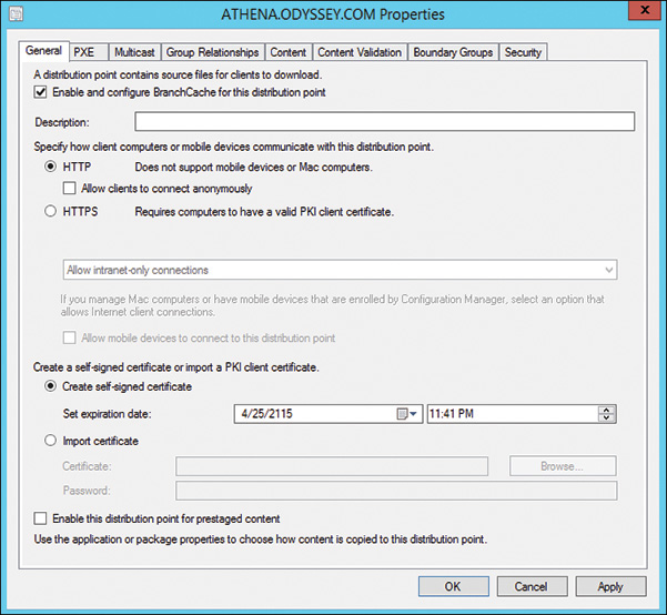
FIGURE 5.7 Specifying to install BranchCache on a DP.
![]() Client side: Configuring the client side is somewhat more difficult. The client machines must have a group policy enabled to turn on BranchCache for them. Find the group policy at Computer Configuration -> Policies -> Administrative Templates -> Network -> BranchCache. Figure 5.8 shows the group policy settings for BranchCache.
Client side: Configuring the client side is somewhat more difficult. The client machines must have a group policy enabled to turn on BranchCache for them. Find the group policy at Computer Configuration -> Policies -> Administrative Templates -> Network -> BranchCache. Figure 5.8 shows the group policy settings for BranchCache.

FIGURE 5.8 BranchCache group policy settings.
At a minimum, you need to enable these two settings in group policy:
![]() Turn on BranchCache
Turn on BranchCache
![]() Set BranchCache Distributed Cache Mode
Set BranchCache Distributed Cache Mode
The authors also recommend you set the following two options:
![]() Configure BranchCache for Network Files: This setting specifies the minimum latency for caching to occur. The client uses the BranchCache feature when it does not receive content from a remote source within the specified interval. The default value is 80ms. Setting a higher value causes more WAN downloads to occur but uses less disk space, I/O, and network throughput on the client systems acting as cache repositories.
Configure BranchCache for Network Files: This setting specifies the minimum latency for caching to occur. The client uses the BranchCache feature when it does not receive content from a remote source within the specified interval. The default value is 80ms. Setting a higher value causes more WAN downloads to occur but uses less disk space, I/O, and network throughput on the client systems acting as cache repositories.
![]() Set Percentage of Disk Space Used for Client Computer Cache: The default setting allows up to 5% of the client disk space for caching. The cache is located under %systemroot%ServiceProfilesNetworkServiceAppDataLocalPeerDistRepub.
Set Percentage of Disk Space Used for Client Computer Cache: The default setting allows up to 5% of the client disk space for caching. The cache is located under %systemroot%ServiceProfilesNetworkServiceAppDataLocalPeerDistRepub.
You must also configure Windows Firewall or third-party firewall software to allow BranchCache transfers and the Web Services Dynamic Discovery (WS-Discovery) protocol to discover cached content.
The last step in getting BranchCache to work with ConfigMgr is to configure your packages or applications to enable BranchCache. For applications, check the Allow Clients to Share Content with Other Clients on the Same Subnet box on the Content tab for the application properties. For packages, the same check box appears on the Distribution Point tab for the deployment properties.
When a BranchCache-enabled client attempts to access content from a server that is not on the local subnet, the client first determines the latency of the connection. If the latency exceeds the configured threshold, the client attempts to discover the content on the local subnet. The first BranchCache-enabled client on the subnet to access the content learns that it is not available locally and retrieves it from the remote DP. The client then caches the content and makes it available to other clients on the same subnet. When other clients later try to access the content, local clients respond that it is available in cache, and the content is sourced locally.
For more in-depth information on BranchCache, see http://technet.microsoft.com/network/dd425028.aspx.
Understanding Peer Cache
New to ConfigMgr Current Branch is Peer Cache for ConfigMgr clients, added with version 1610. Peer Cache is nothing new; it has been around for years as an add-on to ConfigMgr from various manufacturers. What is new is that it is now built into the ConfigMgr client from the ground up. Peer Cache helps you manage deployment of content to clients that have this feature enabled. It enables clients to share the content they have already downloaded with other clients on the same subnet that need the content. In ConfigMgr Current Branch version 1706, Peer Cache supports the distribution of content express installation files for Windows 10 and update files for Office 365. No configurations are needed; this support is automatically built in.
TIP: CONFIGMGR PRE-RELEASE FEATURES
Pre-release features are items in ConfigMgr that have had some testing but not the rigorous extensive testing that production code has been through. They are a new item to ConfigMgr. You should use them in a lab environment until they are released as production features. To enable the use of a pre-release feature, you must consent to using it in the console.
Navigate to Administration -> Overview -> Site Configuration -> Sites and choose Hierarchy Settings either from the ribbon bar or by right-clicking Sites. On the General tab, check the box Consent to Use Pre-release Features, which enables you to turn on pre-release features in the console. Then navigate to Administration -> Overview -> Cloud Services -> Updates and Servicing -> Features, where you can see the list of features for the version of ConfigMgr you have installed. Some of the features will say release, and some will say pre-release. By right-clicking a pre-release feature, you get the option to turn on that pre-release feature. When you turn on a pre-release feature, it appears in the console, so it can be configured and used. The console may need to be restarted before you can see the feature.
Requirements for Peer Cache
As with other features in ConfigMgr, you must consider some requirements in order for Peer Cache to work correctly:
![]() The network access account (NAA) has full rights to the client cache folder: This is a big requirement because in the past, the NAA has always been a domain user with basic permissions on client systems. The NAA must have Full Control permission to the %windir%ccmcache folder. The NAA is used to access the cache folder and allow clients to download the content. Starting with the version of Peer Cache used with ConfigMgr Current Branch version 1706, the NAA is no longer used unless the client is running a task sequence that reboots the machine into Windows Preinstallation Environment (WinPE); in this case, the NAA is still needed to access content from a peer.
The network access account (NAA) has full rights to the client cache folder: This is a big requirement because in the past, the NAA has always been a domain user with basic permissions on client systems. The NAA must have Full Control permission to the %windir%ccmcache folder. The NAA is used to access the cache folder and allow clients to download the content. Starting with the version of Peer Cache used with ConfigMgr Current Branch version 1706, the NAA is no longer used unless the client is running a task sequence that reboots the machine into Windows Preinstallation Environment (WinPE); in this case, the NAA is still needed to access content from a peer.
![]() Peer Cache is only used by clients in the same boundary group: A client can only download content from the peer cache of a machine in the same boundary. When clients request machines that have content for it, peer cache clients with content in the same boundary are returned to the client.
Peer Cache is only used by clients in the same boundary group: A client can only download content from the peer cache of a machine in the same boundary. When clients request machines that have content for it, peer cache clients with content in the same boundary are returned to the client.
![]() Hardware inventory must be up to date: The current boundary of a peer cache content source is determined by the last hardware inventory the client has sent to the database. If a peer cache content source roams to a different boundary but does not submit an updated hardware inventory, a client could download content across a slow network. You should consider whether the machine is prone to roaming or is stationary when choosing what machines will become content peers.
Hardware inventory must be up to date: The current boundary of a peer cache content source is determined by the last hardware inventory the client has sent to the database. If a peer cache content source roams to a different boundary but does not submit an updated hardware inventory, a client could download content across a slow network. You should consider whether the machine is prone to roaming or is stationary when choosing what machines will become content peers.
![]() The type of content does not matter: Any type of content that is in the cache of a peer source can be given out to clients requesting the content. Software updates, packages, applications, and any other content types are all available for download.
The type of content does not matter: Any type of content that is in the cache of a peer source can be given out to clients requesting the content. Software updates, packages, applications, and any other content types are all available for download.
![]() The requesting client does not have to have Peer Cache enabled: Clients without Peer Cache enabled can download content from a Peer Cache–enabled source. This means you can designate several peer cache source content clients in each boundary from which clients can download content.
The requesting client does not have to have Peer Cache enabled: Clients without Peer Cache enabled can download content from a Peer Cache–enabled source. This means you can designate several peer cache source content clients in each boundary from which clients can download content.
Configuring Peer Cache
Configuring Peer Cache is fairly straightforward. You need to first determine who will become a peer cache content source. While you can set up every client to become a peer cache sources, the authors recommend considering the following:
![]() Whether the machine is a desktop or stationary machine: The best machine to act as a peer cache source is one that does not move or change boundaries. The last hardware inventory reported by the machine is used to determine the boundary for which it can serve as a peer cache source. If the machine roams to different boundaries, content might be delivered across a slow network link. You can find out what machines are desktop units by querying their chassis type in the
Whether the machine is a desktop or stationary machine: The best machine to act as a peer cache source is one that does not move or change boundaries. The last hardware inventory reported by the machine is used to determine the boundary for which it can serve as a peer cache source. If the machine roams to different boundaries, content might be delivered across a slow network link. You can find out what machines are desktop units by querying their chassis type in the v_GS_System_Enclosure database view. You end up with a number that corresponds to a chassis type (see https://msdn.microsoft.com/library/aa394474(v=vs.85).aspx). The value for a desktop is 3.
![]() Free disk space: Choose machines with a lot of free disk space, which enables you to have designated machines in boundaries that might have all or a great amount of your content stored in the content cache. The more content you store, the greater the disk space needed. On these machines, increase the client cache amount from the default size so the content is stored longer and is not removed when you need more space in the cache. You can collect this information in hardware inventory, but it is not turned on by default. Enable the
Free disk space: Choose machines with a lot of free disk space, which enables you to have designated machines in boundaries that might have all or a great amount of your content stored in the content cache. The more content you store, the greater the disk space needed. On these machines, increase the client cache amount from the default size so the content is stored longer and is not removed when you need more space in the cache. You can collect this information in hardware inventory, but it is not turned on by default. Enable the Free Space (MB) item in the Logical Disk (SMS_LogicalDisk) class so that it can be returned in hardware inventory. This allows you to query the v_GS_Logical_Disk database view for that information.
![]() Active clients: When searching for a machine, check that it is an active client. You may find the perfect machine to be a peer content source but then learn that it is only turned on once a week. When checking the machine, verify that it is an active client that stays powered on all the time.
Active clients: When searching for a machine, check that it is an active client. You may find the perfect machine to be a peer content source but then learn that it is only turned on once a week. When checking the machine, verify that it is an active client that stays powered on all the time.
When you have found the machines you want to use as peer cache content sources, create a collection and add them to the collection. This allows you to group the machines together. Now you are ready to configure the Peer Cache settings. Because you only want the machines in the collection to receive the Peer Cache policies, you need to create a new custom client device setting. Therefore, navigate to Administration -> Overview -> Site Configuration -> Client Settings and choose Create Custom Client Device Settings either from the ribbon bar or after right-clicking Client Settings. You then see a dialog box that allows you to name the custom device settings and choose the client settings you want to apply to this custom setting. Choose Client Cache Settings, and a new section is added to the dialog box, where you can configure the settings, as shown in Figure 5.9.

FIGURE 5.9 Peer client cache settings.
Use the last four settings on this page to configure the peer client cache settings:
![]() Enable Configuration Manager Client in Full OS to Share Content: This dropdown box allows you to choose Yes or No. Choosing Yes enables this setting and also shows a popup dialog box on the screen. This popup explains that it will automatically configure Windows Firewall on clients to open the ports that you choose to use but that any third-party firewall must have the ports opened manually.
Enable Configuration Manager Client in Full OS to Share Content: This dropdown box allows you to choose Yes or No. Choosing Yes enables this setting and also shows a popup dialog box on the screen. This popup explains that it will automatically configure Windows Firewall on clients to open the ports that you choose to use but that any third-party firewall must have the ports opened manually.
![]() Port for Initial Network Broadcast: This option allows you to choose the port to use for the broadcast. When clients are trying to find a peer cache content source machine, they will broadcast on this port and wait for any machines to answer. Port 8004 is used by default. This port must be opened on any third-party firewalls and routers for communication to work correctly.
Port for Initial Network Broadcast: This option allows you to choose the port to use for the broadcast. When clients are trying to find a peer cache content source machine, they will broadcast on this port and wait for any machines to answer. Port 8004 is used by default. This port must be opened on any third-party firewalls and routers for communication to work correctly.
![]() Enable HTTPS for Client Peer Communication: This dropdown box allows you to choose Yes or No. If you choose Yes, all peer communication occurs across HTTPS.
Enable HTTPS for Client Peer Communication: This dropdown box allows you to choose Yes or No. If you choose Yes, all peer communication occurs across HTTPS.
![]() Port for Content Download from Peer (HTTP/HTTPS): You specify the port number the client will use to download content from the peer cache content source machine. This port is used for HTTP and HTTPS communication, and it must be open on any firewalls or routers.
Port for Content Download from Peer (HTTP/HTTPS): You specify the port number the client will use to download content from the peer cache content source machine. This port is used for HTTP and HTTPS communication, and it must be open on any firewalls or routers.
After configuring these settings, deploy the custom client settings to the collection you created for your peer cache content source machines.
When these machines get the policy to be peer content sources, a hidden IIS web page is installed on each one, and the ports are opened in Windows Firewall to allow incoming connections. This is visible inside the CAS.log file on the peer content source machines. You can also see references to a new service thread for the client, known as the Super Peer service, as well as the website that peer clients will use to connect, called SCCM_BranchCache$. (That is just the name Microsoft used; it has nothing to do with BranchCache itself.) When monitoring the CAS log, you also see references to impersonating the NAA access account credentials. This is how the Super Peer service thread gets access to the Cache folder on the peer source.
Understanding How Peer Cache Works
The next step in the process is getting the content on the peer cache content sources. At this time, there is no pre-cache option; the only way to accomplish this is to deploy the content to the peer cache content source machines by using a deployment task (DT) in ConfigMgr. The authors recommend utilizing the collection used for deploying the custom client device settings or creating a new collection and then creating your deployment and targeting it to that collection. This should occur ahead of time so that when deployment to other systems occurs, the peer content sources already have the content stored in their cache. At this point, when the peer content source machines download the content, it will be from a DP, so ensure that your content is distributed to the correct DPs for the boundaries that your peer content sources are in.
When the peer sources have the content in their cache folders, create your deployment to other systems. When the clients receive the deployment and begin downloading content, a request is made to the MP, asking for DPs in this boundary with the content. The MP queries the database and returns a list of DPs and peer content sources. The client tries to use the peer content sources first and falls back to a DP if it cannot get the content from a peer source. When the download starts, you can monitor the Content Transfer Manager log (ContentTransferManager.log) for an overview of the download. To see detailed information about the download, follow the Data Transfer Service log file (DataTransferService.log). This log file shows information about the machine being connected to for the download, the files being downloaded, the job number used to download the files, errors that might occur during the download, and a success message with the start time, ending time, and amount of time for the download.
On the peer content source side, you can monitor the CAS log file to see the connections and the downloads that are occurring. If you see issues with a download, be sure to view both sides of the download: the client and the peer content source. You typically should not notice a difference between using a peer content source or a DP.
TIP: AUTHENTICATION REQUIRED ERROR
When reviewing DataTransferService.log on the client trying to download content from a peer content source, you will see an error stating that authentication is required. This is because when the client makes a connection to the peer content source, it uses its local machine account first. That machine account does not have any rights on the peer content source.
When this error happens, a few lines later in the log file, you will see that it reverts back to using the NAA. This is why that account needs to have full control permissions on the peer content source’s cache folder.
After the download completes and the applications, packages, or software updates have been installed, the download information is aggregated and sent back to the MP for inclusion into the database once every 24 hours. The data that is sent back is used to populate the new Client Data Sources dashboard, shown in Figure 5.10.
The dashboard has several tiles that display information that tells users what content has been downloaded using DPs, Peer Cache, BranchCache, and cloud DPs. You can also hover over the graphic tiles for a breakdown by size of the downloads of each of the content servers. Remember that this data is sent back from the clients only every 24 hours, which means it may take a day or so for the dashboard to be updated with new data.

Using Boundaries and Boundary Groups
ConfigMgr needs a way to organize together machines that have a common relationship. The machines may be in the same AD site or the same IP subnet. A boundary allows these machines to be grouped together for purposes of content and policy. Boundaries by themselves are not used but become active when added to a boundary group. Boundaries and boundary groups provide the following uses:
![]() Site Assignment: When you choose to use automatic site assignment, the client determines if its current network location (AD site and/or IP subnet/address) falls within a defined boundary. If it does, the client is assigned to the site defined within the boundary group of which the boundary is a member. This is an automatic site assignment process.
Site Assignment: When you choose to use automatic site assignment, the client determines if its current network location (AD site and/or IP subnet/address) falls within a defined boundary. If it does, the client is assigned to the site defined within the boundary group of which the boundary is a member. This is an automatic site assignment process.
![]() Site Systems: A boundary group contains a list of site systems to be used by clients falling within the boundaries of the group. These could be MPs, DPs, or even SMPs. When a site system is added to the boundary group, it can only be used by the clients that fall within the boundaries assigned to the boundary group; this is known as a protected site system.
Site Systems: A boundary group contains a list of site systems to be used by clients falling within the boundaries of the group. These could be MPs, DPs, or even SMPs. When a site system is added to the boundary group, it can only be used by the clients that fall within the boundaries assigned to the boundary group; this is known as a protected site system.
A boundary is defined by using one of the following methods:
![]() Active Directory site
Active Directory site
![]() IP subnet
IP subnet
![]() IP address range
IP address range
![]() IPv6 prefix
IPv6 prefix
In small to medium-sized networks, you should be able to use only the AD site method or perhaps a combination of AD sites and IP subnets. In larger networks, network administrators may be using classless interdomain routing (CIDR) and/or supernetting to define IP subnets (see https://technet.microsoft.com/library/cc958837.aspx for additional information). Note that ConfigMgr does not support these methods. The boundary methods expect AD sites and IP subnets to use a specific subnet mask, based on legacy class assignments. When using CIDR and/or supernetting, you may find that you are using a third boundary type, IP address ranges. Ranges allow you to define a group of IP addresses without being concerned about the type of subnetting that is in place.
If your hierarchy includes workgroup machines or clients residing in a different forest where there is no trust relationship, you must use a boundary method other than AD sites because workgroup machines cannot query AD to retrieve site information.
TIP: IP ADDRESS RANGES AND PERFORMANCE
It is a best practice to use IP address ranges only when all other boundary methods are not an option. This is because the site periodically evaluates boundary members; queries required to access members of an IP address range require a substantially larger use of SQL Server resources than queries accessing members of other boundary types. This is more of an issue with medium to large hierarchies that mostly use IP address ranges.
If a site includes multiple MPs, the client gets a list of all the MPs and randomly chooses one to communicate with to retrieve policies. This could lead to clients across a slow network link communicating with an MP on the other side of the slow link instead of communicating with a local MP. Adding the local MP to the boundary group of the clients across that slow link lets them get a list of preferred MPs; the client then communicates with the preferred MP in its boundary group first, falling back to the MP list only if it cannot communicate with the preferred MP. This can help prevent network congestion on the slow link. The same boundary groups can also contain DPs, providing the client with a location or locations for downloading content.
NOTE: OVERLAPPING BOUNDARIES
Overlapping boundaries are boundaries that include the same network locations and are members of different boundary groups with different site roles assigned to the boundary group. Overlapping boundaries are supported only for content distribution. When a client falls into overlapping boundaries, it receives a complete list of DPs with the content it is requesting, regardless of the site the client is in. This allows the client to randomly choose a DP from which it would like to download content. Auto-site assignment is not supported with overlapping boundaries.
Starting with version 1610, ConfigMgr Current Branch changed how boundary groups work. Previous versions used the concept of fast and slow network links. When adding a site system to a boundary group, you could assign that system as a fast or slow link. You could also assign a DP as a fallback DP, meaning that if the client could not find the content on a DP or was not in the boundaries of a DP, it could use the fallback DP to look for content. This sometimes meant a client might go across a slow network link to pull content from the fallback DP, but at least it could get the content.
In ConfigMgr Current Branch version 1610, Microsoft removed the ability to use fast and slow links when adding site systems to a boundary group. ConfigMgr now automatically adds a default boundary group named Default-Site-Boundary-Group<site code>, which is used when a site upgrades to version 1610. To ensure that the current fallback behavior from the previous version remains available until the new boundary groups and relationships are configured, DPs that are enabled for fallback are added to this new default boundary group.
Adding site systems to a boundary group is the same as with previous versions; you just no longer have a fast or slow link to configure. There is a new tab in the properties of a boundary group called Relationships (see Figure 5.11).

FIGURE 5.11 The Relationships tab of the boundary group properties.
You can use this tab to define the relationship between this boundary group and another boundary group, and you can allow the client to fall back if it cannot find content in its own boundary group. This relationship, called neighbor boundary groups, enables you to create a one-way link between the current boundary group and neighbor boundary groups you add. The client searches for content in its own boundary group and falls back to neighbor boundary groups if the content is not found. You can assign a time value to each neighbor, telling the client how long to wait before falling back to that neighbor to search for content; you can also define a priority list for the neighbors the client will search.
TIP: LINKS BETWEEN A NEW BOUNDARY GROUP AND THE DEFAULT BOUNDARY GROUP
When you create a new boundary group, an implied link is created to the default boundary group for the site. This allows the client to fall back to site systems defined in that default boundary group when it is not in a boundary. It also allows clients to fall back and use these site systems when they cannot find any content in their neighbor boundary groups. When defining neighbors, ensure that you set the time value to something less than the default 120 minutes defined for the default site boundary group. If you don’t, clients will use the default site boundary group before using their neighbors.
For detailed information on these changes to boundary groups, see https://docs.microsoft.com/sccm/core/servers/deploy/configure/define-site-boundaries-and-boundary-groups#a-namebkmkboundarygroupsa-boundary-groups.
About Client Communication Security
This chapter discusses client communication in earlier sections but has not mentioned how to secure that communication. The communication between a client and a site server is secure by default by using a self-signed certificate; however, you might want or need more secure methods of communication. ConfigMgr provides the following methods to enhance client-to-server communications:
![]() Signed Client Data: To protect data sent from clients, you can require a client to sign the data before sending it. To enhance the security even further, you can require the data to be signed using the SHA-256 algorithm.
Signed Client Data: To protect data sent from clients, you can require a client to sign the data before sending it. To enhance the security even further, you can require the data to be signed using the SHA-256 algorithm.
![]() Encryption: While signing the data helps protect it from tampering, encryption protects the data from information disclosure, which means it is not vulnerable to network sniffing devices. 3DES is the encryption technology used when encryption is enabled. It protects inventory data and state messages.
Encryption: While signing the data helps protect it from tampering, encryption protects the data from information disclosure, which means it is not vulnerable to network sniffing devices. 3DES is the encryption technology used when encryption is enabled. It protects inventory data and state messages.
![]() PKI Certificates and HTTPS: When using HTTPS, the client must present a valid authentication certificate issued by the trusted root certificate authority to both the IIS server and the client. When using HTTPS for all client communications, you do not need to use the signing or encryption methods.
PKI Certificates and HTTPS: When using HTTPS, the client must present a valid authentication certificate issued by the trusted root certificate authority to both the IIS server and the client. When using HTTPS for all client communications, you do not need to use the signing or encryption methods.
When ConfigMgr clients request policy, they first get a policy assignment so they know which policies apply to them, and then they request only those policy bodies. Each policy assignment contains the calculated hash for the corresponding policy body. The client retrieves the applicable policy bodies and then calculates the hash on each body. If the hash on a downloaded policy body does not match the hash in the policy assignment, the client discards the policy body.
In-depth information about cryptographic controls for ConfigMgr can be found at https://technet.microsoft.com/library/mt629331.aspx.
Troubleshooting Network-Related Issues
A prerequisite for ConfigMgr to operate correctly is that the underlying network must be working properly. Troubleshooting a network involves several different items, including the following:
![]() Basic connectivity to network services
Basic connectivity to network services
![]() DNS resolution
DNS resolution
![]() Routers and firewall ports
Routers and firewall ports
![]() Congested or slow network links
Congested or slow network links
![]() MPs and DPs
MPs and DPs
![]() Service Principal Names
Service Principal Names
TIP: BE PATIENT WHEN TROUBLESHOOTING NETWORK PROBLEMS
Network issues can be difficult to troubleshoot as they can be intermittent and may return after you think they have been solved. The best plan of attack for these types of issues is to start with a known good baseline and work forward from there. The authors find that they often go back to the very basics of how ConfigMgr works with the network to get that good working baseline. Take your time and be patient when dealing with these types of issues.
The following sections briefly describe some of these issues and tools for troubleshooting these items.
Troubleshooting Basic Network Connectivity
Basic network connectivity refers to the ability to connect to network services such as printers, file shares, and internal and external websites. These services should work correctly without any user intervention; a user should be able to open a browser and connect to any website or print a document on the network printer without issues. The network protocol used to make such connections is TCP/IP.
To troubleshoot basic network connectivity, open a CMD window (by selecting Start -> Run and then typing cmd) and run the following commands (which work much better when you have administrator rights on the workstation):
![]() ipconfig /all—This command provides a considerable amount of information about the TCP/IP configuration on your workstation.
ipconfig /all—This command provides a considerable amount of information about the TCP/IP configuration on your workstation.
Check whether you have a valid IP address from your DHCP server or, if you’re using a static IP address, whether it is correct. An IP address beginning with 169 is an auto-configuration address assigned when the machine cannot communicate with the DHCP server. This would be the first issue to resolve.
Next, check the DNS server address, which needs to be configured to point to the correct DNS server for name resolution.
Another item is the default gateway. This device allows the packets to leave your local network and travel to its destination. If it is not set correctly, your network traffic will not go past local resources.
Figure 5.12 shows the results of running ipconfig /all.

FIGURE 5.12 ipconfig /all results.
TIP: MULTIPLE IP ADDRESSES
It is possible to see results of several IP addresses. If a workstation has a wired connection, a wireless connection, and maybe a VPN connection, you will see multiple IP addresses and other information for IP addresses. You also will see IPv6 information if that is enabled. In these cases, it might be easier to pipe the results to a text file for easier reading. You can do this by running ipconfig /all > ipconfig.txt. The config.txt text file is created in the same folder where you are running the command.
![]() ping—If you determine that the machine has an IP address and the other items check out, you can next test TCP/IP connectivity by performing a ping test. When you use the
ping—If you determine that the machine has an IP address and the other items check out, you can next test TCP/IP connectivity by performing a ping test. When you use the ping command, your machine sends a ping packet to another IP address and waits for a result. If the other machine answers, you see reply messages; if it doesn’t, you see a request timed out message. You can also perform a ping test on your local machine to verify its connectivity: Use the machine’s IP address, which you obtain from the ipconfig command, or the industry standard 127.0.0.1 address, known as a loopback address. If you suspect that the local machine’s IP stack is not working correctly, you should ping the loopback address. Following are the commands for those tests:
ping 127.0.0.1
ping <Remote IP Address that you want to connect to>
Both of these commands should return something similar to the following:
Pinging 127.0.0.1 with 32 bytes of data:
Reply from 127.0.0.1: bytes=32 time<1ms TTL=128
Reply from 127.0.0.1: bytes=32 time<1ms TTL=128
Reply from 127.0.0.1: bytes=32 time<1ms TTL=128
Reply from 127.0.0.1: bytes=32 time<1ms TTL=128
Ping statistics for 127.0.0.1:
Packets: Sent = 4, Received = 4, Lost = 0 (0% loss),
Approximate round trip times in milli-seconds:
Minimum = 0ms, Maximum = 0ms, Average = 0ms
Testing DNS Resolution
To this point, the chapter has discussed pinging an IP address. ConfigMgr only uses FQDNs as a method to communicate; for example, when the client wants to talk to the MP, it starts with the FQDN name of the MP and tries to connect. ConfigMgr relies on the workstation’s underlying network connectivity to perform DNS resolution, resolving that FQDN to an IP address so the network connection can be made. You can test this name resolution by using the ping command; instead of pinging an IP address, though, you ping the machine name. Figure 5.13 shows an example.

FIGURE 5.13 Pinging a machine by name.
Figure 5.13 shows that the ping started with the FQDN, Athena.odyssey.com, which resolved to the IP address 95.211.219.66. The information returned then looks just like the ping in the previous section. Name resolution turns a name into an IP address, and the machine knows how to connect to that IP address. If name resolution is not working, you see results similar to the following:
ping athena.odyssey.com
Ping request could not find host athena.odyssey.com. Please check the name and try again.
Results such as these indicate a problem with DNS, which you can troubleshoot by using the NSlookup command, described at http://support.microsoft.com/kb/200525. To troubleshoot NetBIOS name resolution using Nbtstat and other methods, see http://support.microsoft.com/kb/323388. It is also useful to ping the known IP address of the target machine; if that works, the issue is narrowed to some type of name resolution–related issue.
An additional DNS problem that may arise is an incorrect referral. Incorrect referrals occur when a hostname is used instead of a FQDN and the wrong domain name is appended due to the DNS suffix search order. Incorrect referrals typically result in access denied errors. If you see unexpected access denied errors, ping the site system using both the hostname and FQDN to verify that they resolve to the same address.
TIP: USING THE HOSTS FILE
To further test a DNS issue or to temporarily work around that issue, edit the HOSTS file on the machine you are testing. This file is located at %systemroot%system32driversetc and does not have a file extension. Use an administrator account to run Windows Notepad and then open the file. At the end of the file, enter the IP address and FQDN of the machine you cannot resolve, save the file, and exit Notepad. A machine always reads the HOSTS file for the FQDN of the name before trying to resolve it with another method. When you get a successful ping, fix the DNS issue. Remember to go back and remove the HOSTS file entry.
Troubleshooting Routers and Firewall Ports
When you can get a packet outside the local network, it must pass through a router. A router is a software or hardware device that connects different networks together and allows packets to pass from one network to the other. If a router drops packets or doesn’t allow them to cross networks, your network connection is broken at that particular point. tracert (short for trace route), is a tool you can use to determine if a packet is making it across the routers to its final destination. The program traces the route from where the packet started to its final destination, if it can get that far. The point at which the packet crosses a router is called a hop. tracert shows you the hops to get to the final destination. For a real-world example, Figure 5.14 shows a trace route from the ConfigMgr Unleashed lab to a live website.

FIGURE 5.14 Tracing the route to the bing.com website.
Figure 5.14 shows that the name is resolved and then traces a route to it. There are nine hops, meaning the packet goes over nine routers to get to the address. Hops 5 and 8 show request timed out messages, but hops 6 and 9 look good. It might be that the router could not provide information at the hops where the messages occurred. If you see continuous request timed out messages, it means the packet got lost at that last hop.
If tracert shows that the packet makes it to the final destination, but ping still fails, you may have a port or firewall issue. The firewall could be set so that the machine doesn’t respond to incoming pings, which would cause your pings to fail. Ports blocked by firewalls and routers are common sources of connectivity problems. In other cases, a port may simply not be listening on the system to which you are trying to connect. You can attempt to connect to the specific port on the target system with the telnet command. For example, to verify that you can connect to the Trivial File Transfer Protocol (TFTP) daemon service (port 69) on PXE-enabled DP Charon.Odyssey.com, open a command prompt (by selecting Start -> Run and then typing cmd) and enter the following:
telnet Charon.Odyssey.com 69
If telnet is successful, it will open the telnet screen with a cursor. If the connection fails, you will receive an error message.
When a connection to a port fails, first verify that the service is listening on the appropriate port. On the machine that should receive the connections, enter the command netstat –a to list all connections and listening ports and then check the following:
![]() If the port is not shown, verify that all system requirements and prerequisites are met.
If the port is not shown, verify that all system requirements and prerequisites are met.
![]() If the port displays as enabled, check all network firewall logs for dropped packets.
If the port displays as enabled, check all network firewall logs for dropped packets.
Refer to your network team or vendor firewall documentation for procedures to check firewall logs. Also, check the Windows Firewall logs and settings (see http://technet.microsoft.com/network/bb545423.aspx) and any third-party security software that performs intrusion detection and prevention.
Additional tools are available to troubleshoot port status issues. Consider these examples:
![]() The PortQry command-line utility, downloadable from http://www.microsoft.com/downloads/details.aspx?familyid=89811747-C74B-4638-A2D5-AC828BDC6983&displaylang=en.
The PortQry command-line utility, downloadable from http://www.microsoft.com/downloads/details.aspx?familyid=89811747-C74B-4638-A2D5-AC828BDC6983&displaylang=en.
![]() PortQryUI, which you can download from http://www.microsoft.com/downloads/details.aspx?FamilyID=8355E537-1EA6-4569-AABB-F248F4BD91D0&displaylang=en. PortQryUI provides equivalent functionality to PortQry through a graphical user interface (GUI).
PortQryUI, which you can download from http://www.microsoft.com/downloads/details.aspx?FamilyID=8355E537-1EA6-4569-AABB-F248F4BD91D0&displaylang=en. PortQryUI provides equivalent functionality to PortQry through a graphical user interface (GUI).
You can go to http://www.microsoft.com/downloads and search for PortQry to bring up links for these tools.
Congested or Slow Network Links
You may experience slowness with ConfigMgr and networks, meaning that things don’t happen as fast as they once did. This is often seen with content downloads on clients. You can test slowness with the ping command. From the client, ping the DP from which ConfigMgr is trying to download the content. In the results of the command, notice an item called time. It is written this way in the ping results:
Reply from 172.31.50.53: bytes=32 time=50ms TTL=128
time=50ms means it took 50 milliseconds to get the reply from the destination site. The higher the number, the slower the network. A high value may also be returned if a network is congested. Sometimes the ping times out because the network is slow. In these cases, you can change the ping command line to insert a time to wait before timing out, like this:
Ping –w 3000 <IP address of target system>
In this example, 3000 is the number of milliseconds for the ping command to wait for a reply before timing out.
Testing MPs and DPs
A network issue could be the MP or DP to which you are trying to connect. In ConfigMgr, both the MP and the DP are websites. ConfigMgr provides some commands to test the connectivity to these websites. In your browser, type the following commands to connect to the MP website for testing:
http://<FQDN of the MP>sms_mp/.sms_aut?mplist
http://<FQDN of the MP>/sms_mp/.sms_aut?mpcert
mplist returns a list of the MPs in the same site, and mpcert returns a string of characters corresponding to the MP certificate.
If you are using HTTPS for the MPs, enter the following:
https://<FQDN of the MP>sms_mp/.sms_aut?mplist
https://<FQDN of the MP>/sms_mp/.sms_aut?mpcert
You may run into issues where the client is not downloading the complete package or perhaps cannot find the package on the DP. In such a case, you can test the DP to verify package contents or see if the package is on the DP. Run the following command in your browser window (if using HTTPS, change HTTP to HTTPS):
http://<FQDN of the DP>/SMS_DP_SMSPKG$/<Package ID you want to test>
After entering this command, you are prompted to enter your user ID and password to verify that you have permissions to the content store where the package is located. Once access is granted, a list of package files is returned. Figure 5.15 shows an example of this, using the built-in ConfigMgr client package.

FIGURE 5.15 Testing the contents of a package on a DP.
Troubleshooting Service Principal Names
Service principal names (SPNs) provide information that clients use to identify and mutually authenticate with services using Kerberos authentication. Services use Active Directory SPN registration to make the required information available to clients. Missing or incorrect SPN registration is a common cause of problems with client communications with site systems, such as failure to download content or client approval problems. HTTP 401 errors in client log files, including Datatransferservice.log and ccmexec.log, may indicate problems with SPN registrations. To register the required SPNs properly, consider the following:
![]() If running the SQL Server service using a domain account on the site database server or other roles requiring SQL Server, follow the instructions at http://technet.microsoft.com/library/bb735885.aspx to register the SPN. If the SQL Server service is configured to run under the local system account, the SPN does not need to be manually registered. However, running SQL Server as local system is not recommended for security reasons.
If running the SQL Server service using a domain account on the site database server or other roles requiring SQL Server, follow the instructions at http://technet.microsoft.com/library/bb735885.aspx to register the SPN. If the SQL Server service is configured to run under the local system account, the SPN does not need to be manually registered. However, running SQL Server as local system is not recommended for security reasons.
![]() For site systems that require IIS, if the system is registered in DNS using a CNAME (a DNS alias rather than the actual computer name), you must register the SPN by using the procedure described at http://technet.microsoft.com/library/bb694288.aspx.
For site systems that require IIS, if the system is registered in DNS using a CNAME (a DNS alias rather than the actual computer name), you must register the SPN by using the procedure described at http://technet.microsoft.com/library/bb694288.aspx.
Summary
This chapter provided an in-depth look at one of the underlying prerequisites for ConfigMgr: the network. It discussed how ConfigMgr communicates with its site servers, other sites, and external resources. It talked about the ways clients communicate with site roles such as the MP and DP. It covered where to place servers for the best client performance and how clients use boundaries and boundary groups, BranchCache, and Peer Cache. It discussed communication security, how clients use that security, and other site roles that use that security. The chapter discussed the ports used for communication and the protocols for those ports. It discussed troubleshooting issues, including in-depth information on pings, ping tests, and how to verify that an MP and DP are working correctly.
Chapter 6, “Installing and Updating System Center Configuration Manager,” covers installing and updating ConfigMgr.