
Planning Blocks and Subdivision of Blocks
Abstract
Large projects have to be split into manageable areas or blocks so that the networks do not become unwieldy. This chapter gives examples of how a number of projects can be broken into blocks, each of which could be its own planning network. Examples are given of how each block can be subdivided into strings of activities, which could be arranged by similar items of equipment, trades or disciplines, geographical proximity, operational systems, or stages of completion. The use and advantages of banding a network are also discussed.
Keywords
Planning blocks; banding; subdivision of blocks
Chapter Outline
Before any meaningful programme can be produced, it is essential that careful thought is given to the number and size of networks required. Not only is it desirable to limit the size of the network, but each ‘block’ of networks should be considered in relation to the following aspects:
1. The geographical location of the various portions or blocks of the project;
2. The size and complexity of each block;
4. The process or work being carried out in the block when the plant is complete;
5. The engineering disciplines required during the design and construction stage;
7. The stages at which individual blocks or systems have to be completed, i.e., the construction programme;
For convenience, a block can be defined as a geographical process area within a project, which can be easily identified, usually because it serves a specific function. The importance of choosing the correct blocks, i.e., drawing the demarcation lines in the most advantageous way, cannot be overemphasized. This decision has an effect not only on the number and size of planning networks but also on the organization of the design teams and, in the case of large projects, on the organizational structure of the site management setup.
Because of its importance, a guide is given below which indicates the type of block distribution that may be sensibly selected for various projects. The list is obviously limited, but it should not be too difficult to abstract some firm guidelines to suit the project under consideration.
Pharmaceutical Factory
| Block A | Administration block (offices and laboratories) |
| Block B | Incoming goods area, raw material store |
| Block C | Manufacturing area 1 (pills) |
| Block D | Manufacturing area 2 (capsules) |
| Block E | Manufacturing area 3 (creams) |
| Block F | Boiler house and water treatment |
| Block G | Air-conditioning plant room and electrical distribution control room |
| Block H | Finished goods store and dispatch |
For planning purposes, general site services such as roads, sewers, fencing, and guard houses can be incorporated into Block A or, if extensive, can form a block of their own.
New Housing Estate
| Block A | Low-rise housing area – North |
| Block B | Low-rise housing area – East |
| Block C | Low-rise housing area – South |
| Block D | Low-rise housing area – West |
| Block E | High-rise – Block 1 |
| Block F | High-rise – Block 2 |
| Block G | Shopping precinct |
| Block H | Electricity substation |
Obviously, the number of housing areas or high-rise blocks can vary with the size of the development. Roads and sewers and statutory services are part of their respective housing blocks unless they are constructed earlier as a separate contract, in which case they would form their own block or blocks.
Portland Cement Factory
| Block A | Quarry crushing plant and conveyor |
| Block B | Clay pit and transport of clay |
| Block C | Raw meal mill and silos |
| Block D | Nodulizer plant and precipitators |
| Block E | Preheater and rotary kiln |
| Block F | Cooler and dust extraction |
| Block G | Fuel storage and pulverization |
| Block H | Clinker storage and grinding |
| Block I | Cement storage and bagging |
| Block J | Administration, offices, maintenance workshops, and lorry park |
Here again, the road and sewage system could form a block on its own incorporating the lorry park.
Oil Terminal
| Block A | Crude reception and storage |
| Block B | Stabilization and desalting |
| Block C | Stabilized crude storage |
| Block D | NGL separation plant |
| Block E | NGL storage |
| Block F | Boiler and water treatment |
| Block G | Effluent and ballast treatment |
| Block H | Jetty loading |
| Block J | Administration block and laboratory |
| Block K | Jetty 1 |
| Block L | Jetty 2 |
| Block M | Control room 1 |
| Block N | Control room 2 |
| Block P | Control room 3 |
Here roads, sewers, and underground services are divided into the various operational blocks.
Multi-Storey Block of Offices
| Block A | Basement and piling work |
| Block B | Ground floor |
| Block C | Plant room and boilers |
| Block D | Office floors 1–4 |
| Block E | Office floors 5–8 |
| Block F | Lift well and service shafts |
| Block G | Roof and penthouse |
| Block H | Substation |
| Block J | Computer room |
| Block K | External painting, access road, and underground services |
Clearly, in the construction of a multi-storey building, whether for offices or flats, the method of construction has a great bearing on the programme. There is obviously quite a different sequence required for a block with a central core – especially if sliding formwork is used – than with a more conventional design using reinforced concrete or structural steel columns and beams. The degree of precasting will also have a great influence on the split of the network.
Colliery Surface Reconstruction
| Block A | Headgear and airlocks |
| Block B | Winding house and winder |
| Block C | Mine car layout and heapstead building |
| Block D | Fan house and duct |
| Block E | Picking belt and screen building |
| Block F | Wagon loading and bunkering |
| Block G | Electricity substation, switch room, and lamp room |
| Block H | Administration area and amenities |
| Block J | Baths and canteen (welfare block) |
Roads, sewers, and underground services could be part of Block J or be a separate block.
Bitumen Refinery
| Block A | Crude line and tankage |
| Block B | Process unit |
| Block C | Effluent treatment and oil/water separator |
| Block D | Finished product tankage |
| Block E | Road loading facility, transport garage, and lorry park |
| Block F | Rail loading facility and sidings |
| Block G | Boiler house and water treatment |
| Block H | Fired heater area |
| Block J | Administration building, laboratory, and workshop |
| Block K | Substation |
| Block L | Control room |
Depending on size, the process unit may have to be subdivided into more blocks, but it may be possible to combine K and L. Again, roads and sewers may be separate or part of each block.
Typical Manufacturing Unit
| Block A | Incoming goods ramps and store |
| Block B | Batching unit |
| Block C | Production area 1 |
| Block D | Production area 2 |
| Block E | Production area 3 |
| Block F | Finishing area |
| Block G | Packing area |
| Block H | Finished goods store and dispatch |
| Block J | Boiler room and water treatment |
| Block K | Electrical switch room |
| Block L | Administration block and canteen |
Additional blocks will, of course, be added where complexity or geographical location dictates this.
It must be emphasized that these typical block breakdowns can, at best, be a rough guide, but they do indicate the splits that are possible. When establishing the boundaries of a block, the main points given on p. 46 must be considered.
The interrelationship and interdependence between blocks during the construction stage is, in most cases, remarkably small. The physical connections are usually only a number of pipes, conveyors, cables, underground services, and roads. None of these offers any serious interface problems and should not, therefore, be permitted to unduly influence the choice of blocks. Construction restraints must, of course, be taken into account, but they too must not be allowed to affect the basic block breakdown.
This very important point is only too frequently misunderstood. On a refinery site, for example, a delay in the process unit has hardly any effect on the effluent treatment plant except, of course, right at the end of the job.
In a similar way, the interrelationship at the design stage is often overemphasized. Design networks are usually confined to work in the various engineering departments and need not include such activities as planning and financial approvals or acceptance of codes and standards. These should preferably be obtained in advance by project management. Once the main flow sheets, plot plans, and piping and instrument diagrams have been drafted (i.e., they need not even have been completed), design work can proceed in each block with a considerable degree of independence. For example, the tank farm may be designed quite independently of the process unit or the NGL plant, etc., and the boiler house has little effect on the administration building or the jetties and loading station.
In the case of a single building being divided into blocks, the roof can be designed and detailed independently of the other floors or the basement, provided, of course, that the interface operations such as columns, walls, stairwell, lift shaft, and service ducts have been located and more or less finalized. In short, therefore, the choice of blocks is made as early as possible, taking into account all or most of the factors mentioned before, with particular attention being given to design and construction requirements.
This split into blocks or work areas is, of course, taking place in practice in any design office or site, whether the programme is geared to it or not. One is, in effect, only formalizing an already well-proven and established procedure. Depending on size, most work areas in the design office are serviced by squads or teams, even if they only consist of one person in each discipline who looks after that particular area. The fact that on a small project the person may look after more than one area does not change the principle; it merely means that the team is half an operator instead of one.
On-site, the natural breakdown into work areas is even more obvious. Most disciplines on a site are broken down into gangs, with a ganger or foreman in charge, and, depending again on size and complexity, one or more gangs are allocated to a particular area or block. On very large sites, a number of blocks are usually combined into a complete administrative centre with its own team of supervisors, inspectors, planners, subcontract administrators, and site engineers, headed by an area manager.
No difficulty should, therefore, be experienced in obtaining the cooperation of an experienced site manager when the type, size, and number of blocks are proposed. Indeed, this early discussion serves as an excellent opportunity to involve the site team in the whole planning process, the details of which are added later. By that time, the site team is at least aware of the principles and a potential communication gap, so frequently a problem with construction people has been bridged.
Subdivision of Blocks
One major point that requires stressing covers the composition of a string of activities. It has already been mentioned that the site should be divided into blocks that are compatible with the design networks. However, each block could in itself be a very large area and a complex operational unit. It is necessary, therefore, to subdivide each block into logical units. There are various ways of doing this. The subdivision could be by:
Each subdivision has its own merits and justifies further examination.
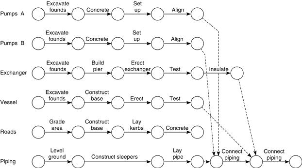
Similar Items of Equipment
Here the network shows a series of strings that collect together similar items of equipment, such as pumps, tanks, vessels, boilers, and roads. This is shown in Figure 20.1.

Advantages:
Trades and Disciplines
This network groups the work according to type. It is shown in Figure 20.2.
Advantages:
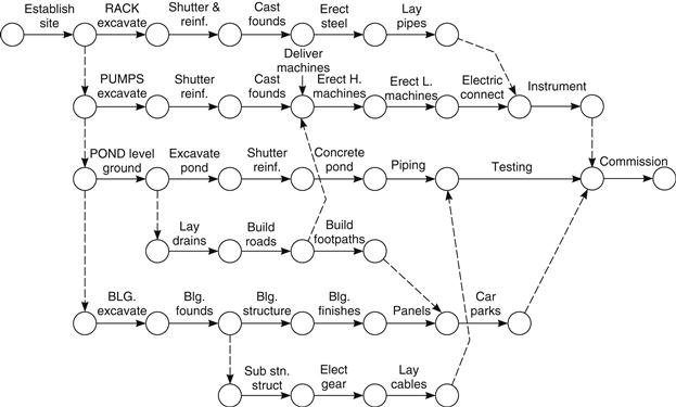
Geographical Proximity
It may be considered useful to group together activities that are geographically close to each other without further segregation into types or trades. This is shown in Figure 20.3.
Advantages:
Operational Systems
Here the network consists of all the activities associated with a particular system such as the boiler plant, the crude oil loading, and the quarry crushing and screening. A typical system network is shown in Figure 20.4.

Advantages:
Stages of Completion
If particular parts of the site have to be completed earlier than others (i.e., if the work has to be handed over to the client in well-defined stages), it is essential that each stage is programmed separately. There will, of course, be interfaces and links with preceding and succeeding stages, but within these boundaries the network should be self-contained.
Advantages:
(a) Attention is drawn to activities requiring early completion;
(b) Predictions for completion of each stage are made more quickly;
(c) Resources can be deployed more efficiently;
(d) Temporary shut-off and blanking-off operations can be highlighted.
In most cases a site network is in fact a combination of a number of the above subdivisions. For example, if the boiler plant and water treatment plant are required first to service an existing operational unit, it would be prudent to draw a network based on operational systems but incorporating also stages of completion. In practice, geographical proximity would almost certainly be equally relevant since the water treatment plant and boiler plant would be adjacent.
It must be emphasized that the networks shown in Figures 20.1 to 20.4 are representative only and do not show the necessary inter relationships or degree of detail normally shown on a practical construction network. The oversimplication on these diagrams may in fact contradict some of the essential requirements discussed in other sections of this book, but it is hoped that the main point, i.e., the differences between the various types of construction network formats, has been highlighted.
Banding
If we study Figure 20.1 we note that it is very easy to find a particular activity on the network. For example, if we wanted to know how long it would take to excavate the foundations of exchanger B, we would look down the column EXCAVATE until we found the line EXCHANGER B, and the intersection of this column and line shows the required excavation activity. This simple identification process was made possible because Figure 20.1 was drawn using very crude subdivisions or bands to separate the various operations.
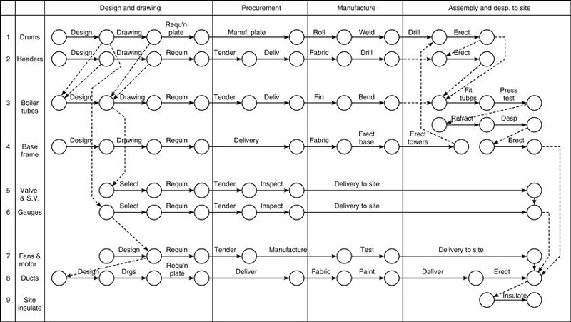
For certain types of work this splitting of the network into sections can be of immense assistance in finding required activities. By listing the various types of equipment or materials vertically on the drawing paper and writing the operations to be performed horizontally, one produces a grid of activities that almost defines the activity. In some instances the line of operations may be replaced by a line of departments involved. For example, the electrical department involvement in the design of a piece of equipment can be found by reading across the equipment line until one comes to the electrical department column.
The principle is shown clearly in Figure 20.5, and it can be seen that the idea can be applied to numerous types of networks. A few examples of banding networks are given below, but these are for guidance only since the actual selection of bands depends on the type of work to be performed and the degree of similarity of operation between the different equipment items.
| Vertical listing | Horizontal listing |
| (Horizontal line) | (Vertical column) |
| Equipment | Operations |
| Equipment | Departments |
| Material | Operations |
| Design stages | Departments |
| Construction stages | Subcontracts |
| Decision stages | Departments |
| Approvals | Authorities (clients) |
| Operations | Department responsibilities |
| Operations | Broad time periods |
It may, of course, be advantageous to reverse the vertical and horizontal bands; when considering, for example, the fifth item on the list, the subcontracts could be listed vertically and the construction stages horizontally. This would most likely be the case when the subcontractors perform similar operations since the actual work stages would then follow logically across the page in the form of normally timed activities. It may indeed be beneficial to draw a small trial network of a few (say, 20–30) activities to establish the best banding configuration.
It can be seen that banding can be combined with the coordinate method of numbering by simply allocating a group of letters of the horizontal coordinates to a particular band.
Banding is particularly beneficial on master networks which cover, by definition, a number of distinct operations or areas, such as design, manufacture, construction, and commissioning. Figure 20.5 is an example of such a network.