
Network Applications Outside the Construction Industry
Abstract
To show that networks, whether in AoA or AoN format, can be successfully used in applications outside the construction industry, the following examples have been given: Bring a new product onto the market, Moving a factory, Centrifugal pump manufacture, Plan a mail order company, Manufacture a package boiler, Manufacture of a cast machine part.
Keywords
Non- construction based networks; Marketing new product; Factory move; Centrifugal pump manufacture; Mail order campaign; Package boiler manufacture; Cast machine part manufacture
Chapter Outline
Bringing a New Product onto the Market
Planning a Mail Order Campaign
Most of the examples of network analysis in this book are taken from the construction industry, mainly because network techniques are particularly suitable for planning and progressing the type of operations found in either the design office or on a site. However, many operations outside the construction industry that comprise a series of sequential and/or parallel activities can benefit from network analysis – indeed, the Polaris project is an example of such an application.
The following examples are included, therefore, to show how other industries can make use of network analysis, but as can be seen from Chapter 26, even the humble task of getting up in the morning can be networked. When network analysis first became known, one men’s magazine even published a critical path network of a seduction!
Bringing a New Product onto the Market
This operations involved in launching a new product and required careful planning and coordination. The example shows how network techniques were used to plan the development, manufacture, and marketing of a new type of water meter for use in countries where these are installed on all premises.
The list of operations are first grouped into five main functions:
| A | Management |
| B | Design and development |
| C | Production |
| D | Purchasing and supply |
| E | Sales and marketing |
Each main function is then divided into activities that have to be carried out in defined sequences and by specific times. The management function would therefore include the following of product:
| A–1 | Definition of product | – size, range, finish, production rate, etc. |
| 2 | Costing | – selling price, manufacturing costs. |
| 3 | Approvals for expenditure | – plant materials, tools and jigs, storage advertising, training, etc. |
| 4 | Periodic reviews | |
| 5 | Instruction to proceed with stages |
The design and development function would consist of:
| B–1 | Product design brief |
| 2 | Specification and parts list |
| 3 | Prototype drawings |
| 4 | Prototype manufacture |
| 5 | Testing and reports |
| 6 | Preliminary costing |
Once the decision has been made to proceed with the meter, the production department will carry out the following activities:
| C–1 | Production planning |
| 2 | Jig tool manufacture |
| 3 | Plant and machinery requisition |
| 4 | Production schedules |
| 5 | Materials requisitions |
| 6 | Assembly-line installation |
| 7 | Automatic testing |
| 8 | Packing bay |
| 9 | Inspection procedures |
| 10 | Labour recruitment and training |
| 11 | Spares schedules |
The purchasing and supply function involves the procurement of all the necessary raw materials and bought-out items and includes the following activities:
| D–1 | Material enquiries |
| 2 | Bought-out items enquiries |
| 3 | Tender documents |
| 4 | Evaluation of bids |
| 5 | Long delivery orders |
| 6 | Short delivery orders |
| 7 | Carton and packaging |
| 8 | Instruction leaflets, etc. |
| 9 | Outside inspection |
The sales and marketing function will obviously interlink with the management function and consists of the following activities:
| E–1 | Sales advice and feedback | |
| 2 | Sales literature | – photographs, copying, printing, films, displays, packaging. |
| 3 | Recruitment of sales staff | |
| 4 | Sales campaign and public relations | |
| 5 | Technical literature | – scope and production. |
| 6 | Market research |
Obviously, the above breakdowns are only indicative and the network shown in Figure 29.1 gives only the main items to be programmed. The actual programme for such a product would be far more detailed and would probably contain about 120 activities.

The final presentation for those who prefer it could then be in bar chart form covering a time span of approximately 18 months from conception to main production run.
Moving a Factory
One of the main considerations in moving the equipment and machinery of a manufacturing unit from one site to another is to carry out the operation with the minimum loss of production. Obviously, at some stage manufacturing must be halted unless certain key equipment is duplicated, but if the final move is carried out during the annual works’ holiday period the loss of output is minimized.
Consideration must therefore be given to the following points:
1. Identifying equipment or machines which can be temporarily dispensed with;
2. Identifying essential equipment and machines;
3. Dismantling problems of each machine;
4. Re-erection on the new site;
6. Transport problems – weight, size, fragility, route restrictions;
10. Readiness of new premises;
13. Announcement of move to customers and suppliers;
14. Communication equipment (telephone, e-mail, fax);
By collecting these activities into main functions, a network can be produced that will facilitate the organization and integration of the main requirements. The main functions would therefore be:
| A | Existing premises and transport; |
| B | New premises – commissioning; |
| C | Services and communications; |
| D | Production and sales; |
| E | Manpower, staffing. |
The network for the complete operation is shown in Figure 29.2. It will be noticed that, as with the previous example, horizontal banding (as described in Chapter 19) is of considerable help in keeping the network disciplined.

By transferring the network onto a bar chart, it will be possible to arrange for certain activities to be carried out at weekends or holidays. This may require a rearrangement of the logic, which, though not giving the most economical answer in a physical sense, is still the best overall financial solution when production and marketing considerations are taken into account.
Centrifugal Pump Manufacture
The following network shows the stages required for manufacturing centrifugal pumps for the process industry. The company providing these pumps has no foundry, so the un-machined castings have to be bought in.
Assuming that the drawings for the pump are complete and the assembly line set up, a large order for a certain range of pumps requires the following main operations:
1. Order castings – bodies, impellers, etc.;
2. Order raw materials for shafts, seal plates, etc.;
3. Order seals, bearings, keys, bolts;
4. Machine castings, impellers, shafts;
9. Issue installation and maintenance instructions and spares list.
Figure 29.3 shows the network of the various operations complete with coordinate node numbers, durations, and earliest start times. The critical path is shown by a thickened line and total float can be seen by inspection. For example, the float of all the activities on line C is 120 – 48 = 72 days. Similarly, the float of all activities on line D is 120 – 48 = 72 days.
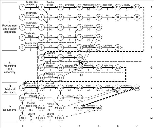
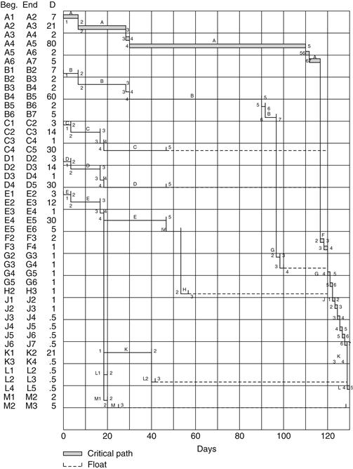
Figure 29.4 is the network redrawn in bar-chart form, on which the floats have been indicated by dotted lines. It is apparent that the preparation of documents such as maintenance manuals, spares lists, and quotes can be delayed without ill effect for a considerable time, thus releasing these technical resources for more urgent work such as tendering for new enquiries.
Planning a Mail Order Campaign
When a mail order house decides to promote a specific product, a properly coordinated sequence of steps has to be followed to ensure that the campaign will have the maximum impact and success. The following example shows the activities required for promoting a new set of record albums and involves both the test campaign and the main sales drive.
The two stages are shown separately on the network (Figure 29.5) since they obviously occur at different times, but in practice intermediate results could affect management decisions on packaging and text on the advertising leaflet. At the end of the test shot management will have to decide on the percentage of records to be ordered to meet the initial demand.

In practice, the test shot will consist of three or more types of advertising leaflet and record packaging, and the result of each type will have to be assessed before the final main campaign leaflets are printed.
Depending on the rate of return of orders, two or more record-ordering and dispatch stages will have to be allowed for. These are shown on the network as B1 and B2.
Manufacture of a Package Boiler
The programme in this example covers the fabrication and assembly of a large package boiler of about 75,000 kg of superheated steam per hour at 30 bar g and a temperature of 300 °C. The separate economizer is not included.
The drum shells, drum ends, tubes, headers, doors, and nozzles are bought out, leaving the following manufacturing operations:
1. Weld drums (longitudinal and circumferential seams);
3. Weld on nozzles and internal supports;
5. Stress relieve top and bottom drums;
6. Bend convection bank tubes;
7. Fit and expand tubes in drums – set up erection frame;
8. Weld fins to furnace tubes; pressure test;
12. Weld and drill headers; stress relieve;
There are four main bands in the manufacturing programme:
| A | Drum manufacture; |
| B | Panel and tube manufacture; |
| C | Assembly; |
| D | Insulation and preparation for dispatch. |
The programme assumes that all materials have been ordered and will be available at the right time. Furthermore, in practice, sub-programmes would be necessary for panel fabrication, which includes blast cleaning the tubes and fin bar, automatic welding, interstage inspection, radiography, and stress relieving. Figure 29.6 shows the main production stages covering a period of approximately seven months.

Manufacture of a Cast Machined Part
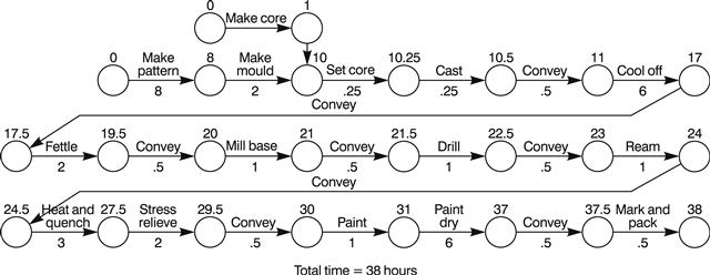
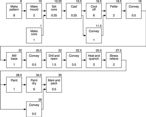
The casting, machining, and finishing of a steel product can be represented in network form as shown in Figure 29.7. It can be seen that the total duration of the originally planned operation is 38 hours, but the aim was to reduce this manufacturing period to make this product more competitive. By incorporating the principle, that efficiency can be increased if some of the operations on a component can be performed while it is on the move between workstations, it is obviously possible to reduce the overall manufacturing time. The obvious activities that can be carried out while the component is actually being transported (usually on a conveyor system) is cooling off, painting, and paint drying. As can be seen from Figure 29.8 such a change in the manufacturing procedure saves three hours.

Any further time savings now require a reduction in duration of some of the individual activities. The first choice must obviously be those with the longest durations, i.e.,
These operations require new engineering solutions. For example, in (1), the pattern may have to be split, with each component being made by a separate pattern maker. It may also be possible to subcontract the pattern to a firm with more resources. Activity (2) can be reduced in time by using forced-draught air to cool the casting before fettling. Care must, of course, be taken not to cool it at such a rate that it causes cracking or other metallurgical changes. Conversely to (2), the paint drying in (3) can be speeded up by blowing warm air over the finished component. If the geographical layout permits it, it may be possible to take the heated air from the cooling process, pass it through a filter, and use it to dry the paint!
Further time reductions are possible by reducing the machining time of the milling and drilling operations. This may mean investing in cutters or drills that can withstand higher cutting speeds. It may also be possible to increase the speed of the different conveyors, which, even on the revised network, make up one hour of the cycle time.
For those planners who are familiar with manufacturing flow charts it may be an advantage to draw the network in precedence (AoN) format (see Chapter 19). Such a representation of the initial and revised networks is shown in Figure 29.9 and 29.10, respectively.

It is important to remember that the network itself does not reduce the overall durations. Its first function is to show in a graphic way the logical interrelationship of the production processes and the conveying requirement between the manufacturing stages. It is then up to the production engineer or controller to examine the network to see where savings can be made. This is, in fact, the second function of the network – to act as a catalyst for the thought processes of the user to give him the inspiration to test a whole series of alternatives until the most economical or fastest production sequence has been achieved.
The use of a PC at this stage will, of course, enable the various trial runs to be carried out quite rapidly, but, as can be seen, even a manual series of tests takes no longer than a few minutes. As explained in Chapter 21, the first operation is to calculate the shortest forward pass – a relatively simple operation – leaving the more complex calculations of float to the computer when the final selection has been made.