
Chapter 15
Versioning
Efficient versioning and configuration management are always important in software development projects. In this chapter we discuss only those MDSD-specific characteristics of this topic.
15.1 What Is Versioned?
In an MDSD project, the following aspects must be managed or versioned:
- The (generic) generation tools. Currently, these tools are often still in development themselves – because of this, it makes sense to have them under version control.
- The generator configuration, the generative part of the domain architecture. This includes the DSL/profile definition, metamodel, templates, and transformations.
- The non-generative part of the domain architecture, the MDSD platform.
- The application itself: models, specifications, and (in most cases) manually-developed code.
The generated code ideally is not versioned, because it is reproducable from the model at any given time, and thus does not constitute a real program source. Of course, this idea can be applied sensibly only if the manually-created and the generated code are separated structurally in the file system. This is one reason why we value this separation (see Section 8.2.6). In practice, it is not always 100% possible or useful, so we sometimes need a more complex procedure for such cases. We discuss this later in this chapter.
One of the goals of model-driven development is the development of several applications based on the same domain architecture. It is therefore essential to separate the platform and the generator configurations from the applications completely.
15.2 Projects and Dependencies
Figure 15.1 provides an overview of a proven project structure. The dashed-lined arrows indicate the dependencies. The main goal is that the domain architecture must be kept clear of application-specific artifacts.
Figure 15.1 Projects and their dependencies.

All the projects shown in Figure 15.1 are managed in the version control system. The tools and the domain architecture are checked in completely, but not the applications: the generated code that is created as the result of running the generator should not be checked in.
It is important to manage the dependencies of the various projects, including their versions. For an application project, it is essential to specify on which version of the domain architecture the project depends. If the underlying platform evolves, you might have to co-evolve the domain architecture, and maybe even the application projects. A framework metaphor is useful to clarify this: imagine the domain architecture as a framework. If you evolve the framework you have to adapt its client applications. These are the same dependencies, so the same methods are applied in the evolution of a domain architecture.
It is worth mentioning that this view can also cascade. For example, it makes sense to version the MDSD platform and the generator configuration in a domain architecture separately, especially when the platform is reused in other domain architectures. On top of this, one will want to version reusable transformation modules (cartridges) separately, and a powerful platform may decompose into a number of decoupled frameworks. In an even more advanced scenario, a functional/professional MDSD platform might have been created with the aid of an architecture-centric domain architecture. These dependencies must be recognized and considered, both in versioning and in the context of architectural dependency management.
15.3 The Structure of Application Projects
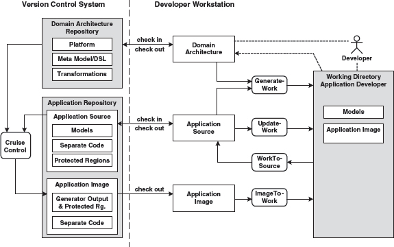
Figure 15.2 shows how an application project can be structured at the highest level and how the generator and compiler work with it.
Figure 15.2 Projects, artifacts, and repositories.

The models of the application, as well as the manually-created code, are located in the application repository. The generator creates the generated code, including configuration files and so on, supported by the generator configuration. The latter is located in the domain architecture repository. The application is next generated with the help of the build script (in most cases this is also generated). This step uses the manually-created code of the application and the platform, the latter taken from the domain architecture repository.
15.4 Version Management and Build Process for Mixed Files
A complete separation of generated and non-generated code is not always possible or sensible. Examples include:
- Custom code in J2EE deployment descriptors.
- Custom code in JSP files.
- Custom code in property files or other configuration files.
In general, these are locations where the target language does not provide sufficient delegation mechanisms.
In these cases one would as a rule work with mechanisms outlined in the case study in Chapter 3: protected regions that can be defined in the generator templates. As a consequence, markings are created in the generated code that are used by the generator during iterative regeneration, to find and preserve the manually-created code contained in it. These markings are hidden syntactically from the compiler or interpreter of the target language by labeling them as comments.
Obviously the use of such protected regions leads to files in which generated and non-generated code is mixed. The problem here is that these files can usually only be versioned as a whole. This results in redundant code being checked in, because the generated code (without the contents of the protected regions) is, after all, not source – the source would be the (partial) model from which the code was generated.
These redundancies can lead to inconsistencies during development in a team. The inconsistencies will become increasingly problematical as the team grows larger: for example, assume that developer A changes something in the model or the architecture while developer B is programming domain logic contained in a file whose generated portion is affected by A’s changes. This situation can cause a problem or conflict when checking in either A or B, because the data is no longer up-to-date. The reason for this is a redundancy in the repository. The objective must be to avoid this redundancy and for example to manage the contents of the protected regions in isolation: the generator must allow this. On the other hand, an isolated protected region is usually of little help to the application developer, because they need the context of the generated code as guidance and to execute the compile-run cycle.
In this situation we need a procedure that avoids redundancy in the repository and offers the developer their familiar, file-oriented view. Figure 15.3 shows such an approach.
Figure 15.3 Version management and build process for mixed files.
The real (that is, non-generated) application sources are managed in the application repository. Manually-created, application-specific source code that is not organized in protected regions is labeled separate code here. In addition, one can automatically – and frequently – create an application image, for example via CruiseControl [CRUI], that contains the generated as well as the manually-created code. Automated tests can then also be initiated on the server.
The developers can now use the well-known check in and check out processes of version management to achieve synchronization with the repositories or modules. The actual application development takes place in a separate work directory. The synchronization between this work directory and the (local) directories that are also controlled during versioning takes place for example via the following scripts or Ant tasks:
- GenerateWork. This script applies the domain architecture on the application model and integrates the checked-out handwritten code from separate files and protected regions with generated code through a generator run. In other words, it produces a complete source code image of the application in the developer’s working directory from scratch.
- UpdateWork. Other than with GenerateWork, no generation takes place here. Only the handwritten code is updated
- WorkToSource. Changes to the working directory are reduced to changes of real sources (generated code is not source) and made available to the version management system, so that check-in can take place in a way that is compatible with the structures in the version control system.
- ImageToWork The result of this script is not very different from GenerateWork. It refreshes the complete source code image in the working directory from the version control system, where it was previously built by a continuous integration server such as CruiseControl. This saves local processing power by delegating a complete build to the server side. Obviously only checked-in content is involved here, in contrast to GenerateWork.
Merge conflicts between developers are exclusively detected using application sources in the repository.
It should be emphasized again that a separation between generated and non-generated code is preferable, in our opinion, and should in any case be attempted.
15.5 Modeling in a Team and Versioning of Partial Models
Big systems must be partitioned. Their constituent parts or subsystems are developed more or less independently of each other. Interfaces define how the systems will interact. Regular integration steps bring the parts together. Such an approach is especially useful if the parts are developed in different locations or by different teams. Of course this primarily affects the development process and communication in the team, possibly also the system architecture. This section casts light on various aspects of this process in the context of versioning.
15.5.1 Partitioning vs. Subdomains
First it is important to point out the difference between partitioning and the use of subdomains (see Figure 15.4):
Figure 15.4 Technical subdomains contrasted with partitioning in a financial example.

- (Technical) subdomains isolate various aspects of the whole system. Each subdomain has its own metamodel and a DSL. The different metamodels are conceptually unified via gateway metaclasses. In the context of an enterprise system, these could be, for example, the subdomains business processes, persistence and GUIs.
- In contrast, partitioning describes the definition of partial systems. For reasons of efficient project organization or complexity, a large number of technically-similar requirements is broken down into separate parts that can be integrated with interfaces.
15.5.2 Various Generative Software Architectures
If different (versions of) generative architectures are used in different partitions of a project, the question arises of whether the generated artifacts will work together. In general, this means that an integration should take place at the level of the generated code. As an example, assume we work with different versions of generative infrastructures that all create parts of a comprehensive J2EE application. Since all generated artifacts must be J2EE-compliant in such a scenario, integration can take place at the level of the finished applications: it is not mandatory that all parts work with the same domain architecture. Such an approach is not ideal, of course, since overall system-wide constraints checking is not possible.
15.5.3 Evolution of the DSL
The DSL typically continues to be developed in the course of one (or more) projects. The knowledge and understanding of the domain grows and deepens, so the DSL will evolve. To make life simpler, one must make sure that the DSL remains backwards-compatible during its evolution.
The approach to versioning in Section 15.5.2 is one way of accomplishing that. Another option is to modify the generator configuration in such a way that it supports different versions of the DSL and metamodel. This should be considered particularly if you work with different versions of the DSL in parallel, for example when application developers switch to a new version of the domain architecture at the end of an iteration. Now a newer – in most cases more powerful – version of the domain architecture is available, while the application models are still using the previous version. In this case, you must provide a migration path that requires as little change as possible on the model from the application developer’s viewpoint. The new features of the DSL should be offered to the developers, not forced on them. Older features might also become deprecated: the generator could issue warnings when such features are used.
In practice, the support of domain architecture versions using generator configurations is not as complicated as it may sound at first. After all, the generator configuration is implemented by the developers of the domain architecture. They define the metamodel and the concrete syntax, as well as the code to be generated. They can, for example, place a version number in the models1 that determines how the generator interprets the model or what code it generates. You can also implement implicit rules: if a certain attribute in the model does not exist, a specific default value is then used. Another example is the validation of attributes of entities. Let’s assume you have a metamodel that contains the concept of an entity. An entity owns a number of attributes. The following listing shows an example model rendered in XML:
<Entity name="Person">
   <Attribute name="name" type="String" label="Name"/>
   <Attribute name="firstname" type="String" label="Firstname"/>
</Entity>
Typically you want to check the attributes for correctness. For this purpose, you can state various constraints. Initially, you might implement this as follows, by simply annotating a named constraint:
<Attribute name="name" type="String" label="Name" constraint="notNull"/>
This asserts that the attribute cannot be left empty. In the course of the project, you might learn that you need more than one constraint, which cannot be expressed adequately with XML attributes. Instead of changing everything, you can now allow the additional constraints as additional XML elements – the old attribute variant can remain:
<Attribute name="name” type="String” label="Name” constraint="notNull">
   <Constraint name="startsWithLetter"/>
</Attribute>
Now you may find out that you need an optional Boolean expression. This can for example be formulated using the target language:
<Attribute name=“age” type=“int” label=“Age”
      constraint=“notNull">
  <Constraint>
    1 <= age <= 110
  </Constraint>
</Attribute>
If this flexibility is still not enough, you can also state a class name in the target language while the respective class implements a validator interface defined by the platform:
<Attribute name=“age” type=“int” label=“Age”
        constraintChecker=“person.AgeChecker”/>
If you continue to develop your DSL in such a way that you keep the old features and add new ones, an evolution of the DSL is easily accomplished in everyday project work. Such mechanisms let you cover an astonishingly large number of cases. Of course this approach increases the complexity of the generator configuration. You should also make sure that outdated features are removed over time. A controlled use of deprecated lets you sort out old features as the project progresses. The generator can easily create a file that logs which features are still in use. This will help you to remove features from the generator configuration that are no longer used – a kind of garbage collection.
15.5.4 Partitioning and Integration
Assume that different teams need the same interfaces, perhaps because one team implements a component that uses code from another team. Figure 15.5 illustrates this:
Figure 15.5 Access to shared model elements.

When your work is model-driven, it is mandatory that at least the model of the interface is available in both models, as shown in Figure 15.6. However, this approach is not ideal, because information is duplicated in the two models, leading to consistency concerns. Depending on the tools, other options exist.
Figure 15.6 Duplication of shared model elements.

Integration in the Model
If the modeling tools support it, you should make sure that the interface only exists in one place and is referenced from both models. From the generator’s view, this results in one consistent model – see Figure 15.7:
Figure 15.7 Sharing of the interface.
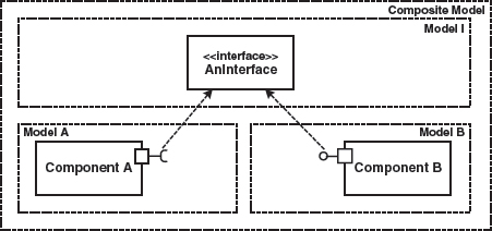
Whether this approach can be realized or not depends on the modeling tools. Among UML tools, repository-based tools that support distributed modeling are ideal.
Integration in the Generator via Model Synchronization
If the modeling tool does not offer adequate integration options, integration can also take place at the generator level. The generator reads several input models that each contain specific model elements, as can be seen in Figure 15.8.
Figure 15.8 Duplication of shared model elements and resolution by the generator.
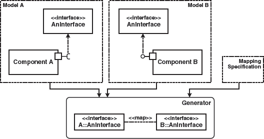
In this case, it is the generator’s task to solve the possible consistency problem:
- The mapping can either be carried out explicitly via a mapping specification, or simply based on identical names.
- Should both model elements (defined by the mapping as identical) differ content-wise, either an error can be reported or an adaption take place. Again, this can be automated to a certain extent.
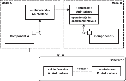
Integration in the Generator via References (Proxy Elements)
A further integration alternative is the use of references, as explained in Section 8.3.4. Figure 15.9 once more illustrates the principle: the interface AnInterface is only present in one model. The other models merely contain references to the interface. Dereferencing can take place via names and is done automatically by the generator.
Figure 15.9 Application of reference model elements to realize commonly used model elements.
1 A portable, tool-independent option of placing versioning information in the UML model allows the model elements to be enriched with the respective tagged values.