Chapter 12
The MDA Standard
This chapter describes important aspects of the MDA, although we do not address all details here, because external literature [Fra02], as well as other resources and the standard itself are available.
12.1 Goals
Model Driven Architecture (MDA) is a term with several different meanings. In the context of this chapter, when we speak of MDA we mean the standardization initiative of the OMG in respect to MDSD. Since MDA does not yet cover the whole MDSD spectrum, one can also think of it as a specific flavor of MDSD.
MDA is a young standard established by the Object Management Group [OMG]. The OMG was founded in 1989 and is an open consortium currently of about 800 companies worldwide. The OMG creates manufacturer-independent specifications to improve the interoperability and portability of software systems. Traditionally the OMG is a platform for middleware and tool manufacturers, serving the synchronization and standardization of their fields of activity. CORBA (Common Object Request Broker Architecture) and IDL, UML (Unified Modeling Language), MOF (Meta Object Facility), and XMI are popular results of this process. MDA is the OMG’s new flagship.
According to the OMG’s directive, the two primary motivations for MDA are the interoperability (independence from manufacturers through standardization) and portability (platform independence) of software systems – the same motivations that resulted in the development of CORBA. In addition, the OMG postulates that the system functionality specification should be separated from the implementation of its functionality on any given platform. From this perspective, the MDA pursues the goal of providing guidelines and standards that will lead to a respective structuring of specifications in the form of models. Last but not least, this approach promises improved maintainability of software systems through a separation of concerns as well as manageability of technological changes.
12.2 Core Concepts
This section looks at the core building blocks of MDA. These are UML 2.0, the Meta Object Facility, XML Metadata Interchange, the three kinds of models (PIM/PSM/PDM), Multi-Stage Transformations, Action Languages, the various core models, model marking, and Executable UML.
12.2.1 UML 2.0
From the MDA perspective UML is central, because many tools are or will be based on UML and profiles. To ensure that this will actually work, the OMG has recently made a few adaptations in the context of UML 2.0 that we introduce briefly here1.
- Infrastructure. Internally, the UML is no longer loosely based on the MOF: the complete UML standards document contains definitions of UML language constructs (that is, of the metamodel) via MOF models. UML is defined formally. This is – as should be clear now – a prerequisite for MDSD, particularly for model transformation and code generation. The OCL also now uses the MOF as its meta meta model: it was necessary to extend the MOF to this end. UML and OCL are now based on the same meta meta model. This makes them conceptually compatible at their cores.
- Extension, profiles, stereotypes. The definition and in part also the notation of profiles and stereotypes – that is, the UML’s native extension mechanism – have been reworked. We will not address this issue here, since it has already been explained in Chapter 6.
Even though formally all MOF-based models can be used in the context of MDA, the UML and corresponding profiles for modeling in the MDA field primarily will prevail, as can be seen from the core models mentioned below. In [Fra02] David Frankel discusses the advantages and disadvantages of the UML in this context. Let’s first look at the advantages:
- Separation of concrete and abstract syntax
- Extensible (via profiles)
- Platform-independent
- Standardized
- Pre- and post-conditions and invariants are possible via OCL (design by contract2)
On the other hand, numerous disadvantages still exist that mainly apply to UML 1.x. Much has been improved with the introduction of UML 2:
- UML is big and badly partitioned
- There is no conceptual support of viewpoints
- Components and patterns receive only little support (improved in UML 2)
- The Relationship model is vague
- It suffers from limited expressiveness of profiles, or generally limited means of adaptation of the metamodel
- UML and MOF are not (yet) correctly fine-tuned to each other (improved in UML 2)
- Diagram interoperability is missing (improved in UML 2)
- There is no abstract syntax for OCL (improved in UML 2)
12.2.2 MOF – The Meta Object Facility
The Meta Object Facility (MOF, see Chapter 6) constitutes the core of the MDA. It describes the meta meta model on which MDA-conforming tools are based – or should be based. The definition of custom DSLs or metamodels should use the mechanisms of the MOF, or extend UML via profiles, which in effect constitutes a ‘lightweight’ metamodel extension. As we have already pointed out, UML is defined via the MOF. The MOF itself uses UML’s concrete syntax, which can cause confusion3. We have implicitly used the MOF’s mechanisms many times in this book. Whenever we extended the UML metamodel, we automatically used the MOF.
The MOF is not only important as a formal basis of metamodels, it is also of concrete relevance for the construction of MDA tools such as repositories, modeling tools, code generators, and so on. Generic tools need a solid basis: this can only be the meta meta model. Similarly, to guarantee the portability of data used in tools, one must agree on a meta meta model. Thus it is essential for the OMG’s standardization efforts and the tool market to define the meta meta model completely, formally, and inherently correctly.
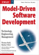
Figure 12.1 shows a part of the MOF.
Figure 12.1 A part of the MOF.
The MOF also has a few disadvantages. One can argue about whether the following aspects should be part of the MOF or not. For example, the MOF does not offer any help in defining a concrete syntax for DSLs or for versioning issues, and the composition of metamodels from partial metamodels is not addressed.
Essential MOF and Complete MOF
Several implementations of the MOF have been created. However, they all only implemented a relevant practical subset of the MOF. Perhaps the most influential implementation was EMF, the Eclipse Modelling Framework [EMF] and it’s eCore meta meta model. Implementation of EMF in turn had an influence on the standardization of MOF 2.0. As a consequence of that influence, the OMG identified a subset of MOF called the essential MOF (eMOF) during the standardization of MOF 2.0 in 2003 that would be sufficient for most meta meta model implementations. Consequently, EMF’s eCore is now compliant with the OMG EMOF standard. You can find a more thorough discussion of eCore (and thus EMOF) in the tools chapter (Section 11.3.1).
Consequently the counterpart of the eMOF is the CMOF. It is used for more complex metamodels such as UML. For example, it combines mechanisms to extend packages by importing, merging, or combining them. It also combines more powerful reflective features.
12.2.3 XMI
XMI stands for XML Metadata Interchange and is an XML mapping for MOF – not just a DTD/schema for UML, as it is often incorrectly stated4. Currently, XMI is the basis for interoperability between different MDA tools because (real, database-based) MOF repositories are yet not widely in use. Since the release of version 2.0, XMI also allows the serialization of diagram layout information, which is mandatory for a practical and useful model exchange between modeling tools, not only for code generation, if you don’t want to rely on the auto-layout mechanisms of the established tools, which are usually poor.
At present there are still many incompatibilities between the XMI formats of different tools, which complicates model exchange between modeling tools. However, the use of XMI as a basis for code generators is not a serious problem in practice, since all popular generators support parsers for the various XMI dialects.
There are two flavors of XMI. The first is a completely generic one that can store all MOF-based models via a generic DTD. The document structure is defined at the MOF level, causing the XMI documents to become rather verbose. A positive fact is that it can be generically applied to all MOF-based models. However, its ability to be read by humans or its suitability for XSLT-based transformations is rather limited.
The XMI standard, however, encompasses the option of generating a DTD or a schema specifically for a given metamodel based on the MOF. As a consequence, documents are only able to store instances of this particular metamodel, but the resulting file is more compact and concrete, because the structures are represented at the metamodel level and not at that of the meta meta model. For obvious reasons, most tools use the first approach for exchange.
Note that a simplified XMI mapping (XMI 2.1) was defined as part of the MOF 2.0 EMOF definition. This should provide better interoperability between tools in the future.
12.2.4 PIM/PSM/PDM
The OMG has a concrete concept of what the MDA should represent. The OMG is not concerned with software system families, the involvement of domain experts, or increased agility in software development, but mainly with platform independence of the application logic. Due to the fact that technological solutions – as well as the business logic – continue to develop quickly yet independently of each other, it is pivotal for reasons of longevity to be able to specify the application logic independently of an implementation platform: in other words, to be able to specify its essence. For this purpose, the OMG considers MOF- or UML-based modeling to be the best solution, because it allows the fully-automated generation of implementations for different platforms via transformers. The platform-independent model (PIM) plays a central role here in describing the business logic undiluted by technical concerns.
A platform-specific model (PSM) is created from the PIM via model transformation. The PSM is, as its name indicates, platform-specific for J2EE, .NET, or other implementation platforms. Further transformations can create increasingly specific models, until eventually the source code for a platform is generated, which is turned into an executable artifact via compilation and packaging.
This discussion emphasizes that both PIM and PSM are relative concepts. A PSM may be specific for J2EE, but still independent of a specific application server. It thus constitutes a PIM in respect to the concrete application server platform.
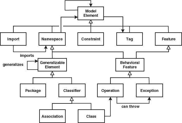
Figure 12.2 shows a taxonomy of the models that play a central role in MDA. (See also [Fra02]).
Figure 12.2 Classification of models in the context of the MDA.
A further important type of model exists in the MDA, the platform description model (PDM). This is the metamodel of the target platform. Due to the fact that model transformations are always defined as transformation rules between metamodels, it is essential to define the target platform via a metamodel as well. The source models use a domain-specific metamodel anyway – possibly a standardized core model (see below). In the context of architecture-centric MDSD, modeling builds directly on the PDM, the architecture metamodel of the target platform.
12.2.5 Multi-stage Transformations
In the examples and best practices described in this book, we have in most cases generated the source code for a certain platform directly from (PIM) models. We did this mainly for pragmatic reasons: model transformation tools that support multi-stage transformations for large systems in a manner that is suitable for everyday use do not yet exist.
The MDA pursues the goal of obtaining source code via several subsequent model-to-model transformations. This clearly has advantages given that the right tools are available. The example in Section 11.2.3 shows why, and also clarifies why one tries to do as much as possible at the model level in MDA and to leave the information in model form as long as possible. The transformation engines are defined based on the MOF. As long as we deal with MOF-based metamodels such tools can be used, but as soon as we enter the ‘lowlands’ of programming, they aren’t very useful anymore. One would have to define classical programming languages via the MOF, with the result that the transformations would become very complex compared to simple templates.
In some cases it is necessary to configure the intermediate products manually to control their further transformation stages. The OMG calls such a configuration model markings. Model markings cannot be annotated directly in the PIM, because this would involve the risk of losing platform independence. For consistency reasons, it is also critical not to modify the intermediate models. We suggest the use of external model markings, as explained in Section 8.3.5.
12.2.6 Action Languages
At some point the justifiable objection that today you cannot model a complete software system via UML (or other MOF-based languages) may have come to mind while reading this book. This is partially true. Yet we have already shown that you can model domains to a large extent if you limit the domain sufficiently, strongly standardize its concepts, and define a suitable DSL. Many aspects will of course remain unresolved or impracticable: specifically, a way of specifying algorithmic behavior is still missing.
To address this problem, the OMG defines the action semantics with UML 2.0, which can also be used with other MOF-based languages. Action semantics support modeling of procedural behavior. Note that the OMG only defines only the abstract syntax, not a concrete syntax. The semantics are described verbally. It is therefore up to the tool manufacturers to define their own textual or graphical notations. It is thus possible to represent the same behavior both textually and graphically.
The action semantics comprise the following elements:
- Variables (instance handles): assigning, reading, also for sets of variables (sets, bags, sequences)
- The usual arithmetic and logical operations
- Typical features of sequential programming languages such as switch, if, for, statements, the block concept
- Instance creation, destruction of instances
- Class extents that can be prompted with SQL-like queries
- Navigation across associations
- Creation of links (instantiation of associations) and the deletion of links
- Generation of signals, including parameters
- Definition of functions with input and output parameters, and ways of calling them
- Timers
Action semantics do not contain structural constructs such as classes, attributes, and relationships. These are already defined in the structural part of the model. Action semantics merely define ‘behavioral building blocks’ that only make sense in connection with other (partial) models. As a consequence, action semantics segments are always associated with elements of the regular UML model, for example with the operations of classes, or onEntry actions in state machines.
Here is a simple example of the use of action languages. Figure 12.3 shows the class diagram, which serves as a basis for the example. We use the syntax that is used in the tool iUML by Kennedy Carter [IUML].
Figure 12.3 A simple model to illustrate action semantics.

First, we implement a ‘main program’ that works with instances of classes from Figure 12.3 and creates an instance of the class Vehicle. Then we assign a value to the make and the model.
myVWBus = create Vehicle with plate = “HDH-GS 142”
myVWBus.make = “Volkswagen”
myVWBus.model = “Transporter T4 TDI”
The with clause assigns values to the identifying attributes (see the «id» stereotype) as early as during object creation, similar to passing constructor parameters in OO languages. Then we can define an instance of Person that will subsequently become the driver.
We can now call the operation drive() to let the driver drive the vehicle.
[actualDriver] = drive[aVehicle] on john
What is still missing, of course, is the implementation of the operation drive(). The least it must do is to instantiate the association R1 – that is, to create a link between the two relevant objects.
link this R1 aVehicle
This establishes the bidirectional association between the Vehicle and a driver. Now you can ask the car who is currently driving it. This corresponds with the implementation of the drive() operation of the class Vehicle.
theCurrentDriver = this.R1."driver”
Now we briefly introduce the query operations. Let’s assume that we want to find all the individuals in the system:
{allPersons} = find-all Person
The braces state that allPersons is a set of objects instead of just one. It’s also possible to limit such a search. For example, all vehicles of the brand Audi can be looked for:
{audis} = find Vehicle where make = “Audi”
One could criticize the fact that action semantics are just another programming language. In principle, this is correct, but it misses the point:
- One doesn’t have to deal with platform specifics such as memory management, the definition of a link between two EntityBean instances, or the use of relational keys.
- We are dealing with ‘semantic building blocks’ here. The concrete syntax can look different. In principle, the same could be accomplished with traditional languages, but this is not common.
- Action semantics are totally integrated in the model: the concluding example clarifies this.
Let’s assume we are dealing with the trivial model in Figure 12.4. To the right we can see a few lines of action language.
Figure 12.4 Another example of a model.

During the mapping to a programming language – that is, during implementation code generation – the following approximate code is generated:
| Line 1 | Creation of a new instance of A, creation of variable a. |
| Line 2 | Creation of a new instance of B, creation of variable b. |
| Line 3 | Now things become more interesting: the attribute theB is assigned a pointer to b. Since the association is bidirectional, b.theA will also automatically point to a. This is something the programmer need not explicitly program – the generator can do this automatically using the information in the class diagram. |
| Line 4 | Due to the fact that B is compositionally associated with A, the generator can create code that will delete instance b when a is deleted. |
The information for code generation is also taken from the structure diagram. The developer only has to write the link… statement in ASL: the – potentially significantly more complex – implementation code is generated automatically.
Let’s once more address the abstraction effect of action semantics. This textual representation says nothing about its realization, of course. If the respective system is implemented with EJB, for example, you would generate different code than you would were you generating the implementation for some embedded system.
12.2.7 Core Models
To be able to benefit as much as possible from the MDA, as many aspects as possible must be standardized. This includes platforms — already done via J2EE, .NET, CORBA or Web Services, at least on the technical level — and transformation languages, which happens in the context of QVT (see Chapter 10). To allow users to model the application logic independently of the platform, it is also necessary to standardize the metamodel for specific domains. Thus it not only becomes possible to standardize the transformation languages, but also to capture reusable transformation rules in transformation libraries. The developer models their application via the standardized UML profile or metamodel for the respective domain, and commercial or Open Source transformation modules generate the platform-specific code from it.
These standardized metamodels are called core models by the OMG in the context of the MDA. Various core models are being developed5 currently that are at present all defined as UML profiles. Among these are:
- UML profile for CORBA, which defines the mapping of PIMs to CORBA.
- UML profile for CCM, which defines the mapping to CCM, the CORBA component model.
- UML profile for EDOC, which defines the metamodel for the definition of PIMs for distributed enterprise systems.
- UML profile for EAI, which defines the metamodel for PIMs for EAI applications and other loosely-coupled systems.
- UML profile for Quality of Service (QoS) and Fault Tolerance, for real-time and safety-critical systems.
- UML profile for Schedulability, Performance and Time, which defines a metamodel for PIMs whose real-time properties can be analyzed quantitatively.
- UML Testing Profile, which supports automated testing in MDA-based systems.
The current status of the various profiles can be looked up at [OMGP].
12.2.8 Controlling the PIM to PSM Transformation
In some cases the transformation engine cannot transform a model because the information in the source model is not specific enough. For example, the target metamodel can offer different ways of realizing a construct of the source metamodel. In [Fra02] David Frankel describes four alternatives way of proceeding in such a case:
- You can encode into the transformation the fact that a particular alternative shall always be used.
- The developer can define which of the alternatives shall be used manually.
- Developers can state directly in the PIM which alternatives should be used in the PSM as model markings – see below.
- The decision criteria that let the transformer decide which alternative should be used can be abstracted into the PIM (more about this later).
Model Markings
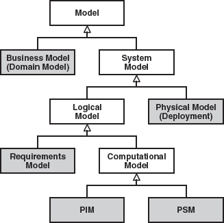
The MDA proposes the concept of model markings. Model markings are additional information in a transformation’s source model that control the transformation. These annotations depend typically on the target metamodel. Figure 12.5 illustrates the principle.
Figure 12.5 An example of model markings.

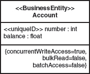
J2EE again serves as an example here. In the PIM we define a BusinessEntity called Account. In J2EE, BusinessEntities can be represented in two different ways: either as EntityBeans, or as Stateless Session Beans that process data transfer objects. One could mark the source model as shown in Figure 12.6.
Figure 12.6 An example of an entity with EJB-specific markings.

It is important to ensure that the source model itself is not changed: instead, a ‘reference copy’ is defined that contains additional information. Figure 12.7 illustrates this idea.
Figure 12.7 The relationship between PIM and marked PIM.
The marked PIM only contains model elements of the original PIMs that should be marked, or rather, only the additional markings themselves. This means that the marked PIM does not need to be adapted manually if the PIM is changed6.
Decision Criteria in the PIM
There is another option that allows you to work mostly without markings if you are prepared to accept other consequences. This mechanism requires you to extend the source metamodel in such a way that enough information is present in the model for the generator to choose between the different alternatives. Figure 12.8 shows what this could look like:
Figure 12.8 Entity with target-platform-independent markings.
The decision about which implementation alternative to use in which case in J2EE can now be delegated to the J2EE transformations. Of course, the metamodel must be extended, and this is not always possible. However, the metamodel is not extended using the concepts of the target metamodel, but with general information that can be used by the transformer. This constitutes an enrichment of the source metamodel, rather than a ‘pollution’ of it with target metamodel-specific constructs.
12.2.9 Executable UML
The term Executable UML is often heard in the context of MDA. This is not a formal standard, but a collective term for various endeavors that all pursue the goal of establishing UML as a fully-fledged programming language. To this end, UML must be purged of all redundancy and ambiguities, resulting in executability of UML diagrams: the smaller the metamodel of the modeling language (here UML), the easier it is to implement a compiler or an interpreter for it. Another necessary ingredient of executable UML is an action language (see Section 12.2.6), which is necessary to define complete implementations of software systems.
It is important to understand that – contrary to the MDSD approach – executable UML is not a domain-specific profile of UML. The idea is rather to define a universal, UML-based programming language.
Further information about executable UML can be found in Steve Mellor’s book [Mel02] or in the documentation section of Kennedy Carter’s iUML [IUML].
1 Much more than we describe here has actually been added. Here we only focus on those aspects that are directly relevant to MDA.
2 Design by contract is well-known term in computer science that describes the idea that operations define what they expect to be true when called, and that they define what they guarantee to be true after their execution.
3 More precisely, the core of UML (that is, the classifier package) can be applied on all metalevels since the introduction of UML 2.0. Thus it also constitutes the core of the MOF.
4 Typically XMI is specifically used for the serialization of UML models.
5 If this looks familiar to you it is probably because, prior to the introduction of MDA, attempts were made to standardize profiles for certain domains.
6 This clarifies how important it is for MDA that the modeling tools provide the according powerful repositories and functionalities. Most of today’s modeling tools have not reached this level yet.