
Chapter 3
Case Study: A Typical Web Application
After we have established the foundations for MDSD in general, and Architecture-Centric, Model-Driven Software Development (AC-MDSD) in particular, we can now proceed to a hands-on case study to familiarize ourselves with AC-MDSD in practice.
3.1 Application Development
First, we assume the application developer’s position and presuppose the existence of a generative software architecture, as described in Section 2.5. This will typically be created iteratively and incrementally in parallel with application development. We will discuss the methodology required for this purpose in greater detail in Chapter 13.
We should mention that this is a role-based view. However, we will not say anything about the allocation of roles to people yet, since this is a matter of project organization, which is covered in Chapter 19. Here we focus primarily on categorizing the various activities to help an understanding of the subject matter. Based on an example application, we explain the most important steps, then proceed to describe the relationship between application development and the generative architecture.
An iteration in application development begins with the creation or extension of an application design, in this example using a UML tool. The application design’s XMI1 representation, exported from the UML tool, is transformed into an implementation skeleton via an MDSD generator. The actual business logic is programmed manually and integrated into the generated infrastructure code. To this end, we use protected regions, also known as protected areas. Syntactically, these are comments in the target language, but are interpreted by the MDSD generator. Each protected region within the generated code possesses a globally unique identifier disguised as a comment, and is thus uniquely linked to a model element. In this way the generator can protect the contents of these regions, insofar as it re-inserts their contents at the correct locations in the generated code during iterative regeneration. This procedure is also quite robust with respect to renamings in the model, because the protected regions’ IDs are generated from UUIDs2 of the model (more precisely, from the XMI format), rather than from names of model elements such as class names or something similar. The content of its protected regions will be deleted only if you delete a model element.
Protected regions are not always the best means for integrating generated and manually programmed code, but this is not our concern yet.
3.1.1 The Application Example
The following example has been taken from an MDA/MDSD tutorial, and has been presented as a ‘hands-on’ session with great success at various conferences (JAX, OOP, and others). The application was created to illustrate a holistic software development approach, ranging over business process analysis, architecture-centric design, and model-driven code generation, to the implementation of the business logic, while being based on a simple but non-trivial example. The analysis model was taken from tutorial material from oose.de GmbH, and the generative software architecture was built by b+m Informatik AG.
The example describes the development of an information system for a car-sharing company. Figure 3.1 shows the use-case overview of the fictitious application ‘Car-Sharing 1.0’.
Figure 3.1 Use case overview of the car-sharing application.

Car-Sharing Version 1.0 implements the system use case ‘Make car reservation’ and allows car reservations as well as car management. The members of the car-sharing community are registered in the system for authorization and – later – billing purposes. The main purpose of the system is the electronic execution of car reservations through call-center agents.
The architecture of the car-sharing application is a classic three-tier architecture, consisting of a presentation layer, a process layer, and a persistence layer – see Figure 3.2. It is based on the J2EE framework.
Figure 3.2 Car sharing architecture.

The presentation layer uses the MVC pattern based on the Servlet Model 2 architecture à la Struts [STRT]. All HTTP requests from the browser are intercepted centrally by a FrontController, then evaluated and dispatched to the respective view to be displayed. The FrontController delegates the evaluation and processing of triggered GUI actions, as well as the evaluation of guards in the navigation sequence to the according SubController. The SubController provides the data required by a View’s display in the form of a ViewModel. For the purposes of flow control, this layer uses the Struts framework. Data exchange with the process layer takes place via ValueObjects. The process layer offers the presentation layer’s controllers stateless transactional services in the form of methods on ProcessObjects. These process objects allow controllers to read the view-relevant data and to store newly-received data. At the same time, entities located in the persistence layer are protected from being directly accessed by objects in the presentation layer.
The persistence layer uses a persistent business object model (BOM) that is implemented using Java Entity Beans. Persistence is handled by the CMP mechanism (Container Managed Persistence) in combination with a relational database. The target platform and runtime environment of the application are built exclusively from Open Source software: a Tomcat Web server [TOMC], the EJB 2.0-compliant application server JBoss [JBOS], and the HyperSonic SQL [HSQL] database. The runtime environment’s central element is the Struts framework, which controls the application’s processes. In addition, the runtime environment is completed by some super and helper classes.
The creation of the car-sharing application’s design in the form of a PIM is conducted with the help of a design language (UML profile) which describes architecture concepts. In the UML profile we can find the concepts that were laid out in the conceptual architecture overview in a simplified form (for example EntityObject, ValueObject and so on). We discuss the exact profile definition later. Transformation to the target platform (the platform binding) is achieved via a set of generator templates that generate the required source code from the model. The design language and the platform binding, in the form of templates, make up the generative software architecture (Section 2.5), which can be seen in Figure 3.3.
Figure 3.3 Generative software architecture and runtime environment.

3.1.2 MDSD Tools
To apply AC-MDSD in practice we need a UML modeling tool and an MDSD generator. The UML tool must be able work with UML profiles. At present, no mainstream UML tool exists that is able to evaluate modeling constraints, that is, able to check the assertions made on the metalevel in the form of OCL expressions3. Checking constraints therefore needs to be supported by the MDSD generator.
The generator tool must read the models provided by the respective UML tool and use them as input for generation. Today, most UML tools are able to save models in XMI format, but XMI quality varies. Thus the MDSD generator should offer predefined and customizable adapters for different modeling tools.
A more detailed discussion of tools and requirements can be found in Chapter 11.
In our scenario, we use the UML tool Poseidon UML Community Edition from Gentleware [POSE], whose XMI output is transformed into source code by the openArchitectureWare generator framework [OAW] via generator templates. This source code is then further modified in the Eclipse IDE [ECLI]. The generator framework is supplemented with an Eclipse plug-in, so that its use in an integrated development environment is feasible. It also meets the requirements stated above.
The following examples outline the developer’s activities at the various levels of application programming that occur in the course of the design/generate/build cycle.
3.1.3 Example 1: Simple Changes to Models
The first example describes a simple change to the static class model of the car-sharing application and the execution of one cycle of design, generate and build. Since the JSPs required for the car-sharing application are completely generated from the information in the class that has the «Presentation» stereotype, it is a good idea to change something in the presentation layer (see Figure 3.4).
Figure 3.4 Transformation of UserRegistration model to the concrete dialog UserRegistrationView.

The left part of Figure 3.4 shows the presentation class UserRegistration, and the right-hand side shows the dialog (JSP) that is generated from it, after HTML rendering. The methods of the Presentation class have as their counterparts the Continue buttons in the browser’s JSP presentation. The renaming of the method Finish to Exit in the UserRegistration class results in a change of the respective button’s label, as you can see from the dialog. Besides the JSP, the Struts ActionForm, which constitutes a View Model, is completely generated from the presentation class.
The following code shows the generated JSP UserRegistration.jsp.
…
<html:form action="<%= (String) request.getAttribute(“FormAction”) %>“ method=“Post”>
  <table border=“0” cellspacing=“0” cellpadding=“0” >
  <tr>
   <td><bean:message
key=“de.amg.carsharing.user.presentation.UserRegistration.userid”/> </td>
   <td>
    <html:text property=“userid”/>
   </td>
   </tr>
  <tr>
    <td><bean:message
key=“de.amg.carsharing.user.presentation.UserRegistration.password”/> </td>
    <td>
     <html:password property=“password”/>
    </td>
  </tr>
  <tr>
   <td>
    <input type=“hidden” name=“registration.jsp.Event” value=“Continue”>
    <input type=“submit” name=“Event” value=“Continue”/>
   </td>
   <td>
    <input type=“hidden” name=“registration.jsp.Event” value=“Exit”>
    <input type=“submit” name=“Event” value=“Exit”/>
   </td>
  </tr>
  </table>
</html:form>
…
The following listing shows the form class behind it:
  package de.amg.carsharing.user.presentation;

  import org.apache.struts.action.ActionForm;
  public class UserRegistrationForm extends ActionForm
  {
   private String userid;
   private String password;
   public String getUserId()
  {
     return userid;
  }
  public void setUserId(String aUserId)
  {
     userid = aUserId;
  }
  public String getPassword()
  {
     return password;
  }
  public void setPassword(String aPassword)
  {
     password = aPassword;
  }
}
Where simple changes during development are concerned, we work exclusively at the model level. After such changes have been made, the model is exported to XMI format. The generator interprets the XMI and generates the corresponding sources. Building as well as deployment both take place in the IDE or via Ant [ANT].
It is clear that the model here plays the role of source code – all information regarding the change is kept in the model. It is therefore advisable to integrate the model into the application’s release management in addition to the actual sources.
3.1.4 Example 2: Model Changes and Protected Regions
The second example illustrates how individual parts of business logic in protected regions can be supplied. For this purpose, we look at how a parameter that is required for making reservations is determined in the process layer and made available to the presentation layer.
Figure 3.5 shows the part of the model that is needed in the process layer. Here, the MakeReservationPO gets the getReservationParameter() method, which returns ReservationParameterVO. The ReservationParameterVO serves as a data container to enable passing of data from the process layer to the presentation layer. During generation, all classes, Java interfaces and deployment descriptors necessary for the execution of MakeReservationPO in a Session Bean are generated from this model. Additionally, a MakeReservationBusinessDelegate is generated that is based on the business delegate pattern from the J2EE core patterns [CORE]. The Reservation-Para meterVO is 100% generated, whereas for the method getReservationParameter() only the method signature is generated. The implementation must be added manually in the IDE. This is done in protected regions, as the following code excerpt illustrates:
Figure 3.5 MakeReservation process view.

public ReservationParameterValueObject
    getReservationParameter()
   throws RemoteException {
   // PROTECTED REGION ID(12Operation_MethodBody) START
   ReservationParameterValueObject vo = null;
   try
   {
    CarSharingModuleComponent component =
      new CarSharingModuleComponentImpl();
    StationHome home = component.getStationHome();
    Collection stations = home.findByAll();
    Collection colStations = new ArrayList();
    for (Iterator i = stations.iterator();
            i.hasNext(); ) {
      Station station = (Station) i.next();
      colStations.add(station.getName());
    }
    Collection colCarCategories = new ArrayList();
    colCarCategories.add(CarCategory.COMPACT);
    colCarCategories.add(CarCategory.VAN);
    colCarCategories.add(CarCategory.SPORT); colCarCategories.add(CarCategory.LUXURY);
    vo = new ReservationParameterValueObject( colStations, colCarCategories);
  }
  catch (Exception e) {
    e.printStackTrace();
    throw new RemoteException(“Error: “+
        “Registration parameter search failed”, e);
  }

  return vo;

  // PROTECTED REGION END
}
The decision as to whether protected code regions are required or not must be made at the architecture level when the generator templates are created (see Section 3.2). Additions or changes outside these protected areas are not allowed, because they would undermine the clear separation between modeling and programming on one hand, and between application and architecture modeling on the other: design changes must be made in the design (the application model) and architectural changes – that is, systematic changes to the generated code – must be made in the generative architecture. The generator framework ensures this: changes that are made outside protected regions will get lost in the course of iterative regeneration. This is not intended to restrict the freedom of application developers, but guarantees consistency, as well as regular communication between application and architecture development. The definition of this boundary between generated and non-generated code is pivotal and its handling requires some experience. This subject is described in more detail in Chapter 7.
3.1.5 Example 3: Working with Dynamic Models
Besides the options for generation of source code based on static models, as shown in the previous examples, dynamic models such as activity diagrams and state diagrams can also be used for code generation. This example describes how this can work. Figure 3.6 shows an activity diagram before and after a change in the navigation order of the resulting application. In the new version, the step leading to the identification of the calling member must be carried out before a user registration can take place. (Whether this makes sense or not is open to dispute.)
Figure 3.6 Change in the navigation order.

Since we chose Struts as the control flow framework for our example, the necessary flow control configurations must be generated based on the activity diagram. The following excerpt from the Struts configuration shows what this looks like:
<!-- ControllerState “UserRegistration” -->
<action
  path=“/ UserRegistration_a64aa2a7d0162ba7ffb_Init”
  type=“de.amg.carsharing.user.
          presentation.UserRegistrationController”
  name=“UserRegistrationForm”
  input=“/UserRegistration.jsp”
  scope=“request”
  parameter=“UserRegistration_Init,a6488aa27d162ba7ffb”>
    <forward name=“Ok”
          path=“/UserRegistration.jsp”
          contextRelative=“true”
    />
</action>
  <action
  path=“/UserRegistration_a64aa2a7d0162ba7ffb_Exit”
  type=“de.amg.carsharing.user.
          presentation.UserRegistrationController”
  name=“UserRegistrationForm”
  input=“/UserRegistration.jsp”
  scope=“request”
  parameter=“UserRegistration_Exit, a6488aa27d162ba7ffb “>
    <forward name=“UserRegistration_To_Exit”
          path=“/MemberIdInput_a6affa_Init.do”
    />
    <forward name=“Continue”
          path=“/SelectCategory_a64aac9_Init.do”
    />
    <forward name=“Error”
          path=“/UserRegistration_a64aa30f0fbfb_Init.do”
    />
  </action>
The following XML fragment is an extract from the corresponding Struts config.xml, which controls the acquisition of the member ID4.
<!-- ControllerState “MemberIdInput” -->
<action
  path=“/MemberIdInput_a64aa3a062ba7ffa_Init”
  type=“de.amg.carsharing.member.
        presentation.MemberIdentificationController”
  name=“MemberIdentificationForm”
  input=“/MemberIdentification.jsp” scope=“request”
  parameter=“MemberIdInput_Init,a60f06b7f”>
    <forward name=“Ok”
        path=“/MemberIdentification.jsp”
        contextRelative=“true”
    />
</action>
The control flow can be generated completely from the application design. Further manual manipulations of the Struts configuration are not required. Our experience shows that this is particularly advantageous, because activity diagrams also document the navigation extremely well and can thus be used for discussion with domain experts.
3.1.6 Interaction Between Development and Architecture
Good coordination between application development and architecture is the key to success in MDSD projects. Development of the generative architecture is not finished when the generative software architecture has been delivered. As the application development steps described in our examples show, in most cases requirements for change of the generative software architecture will emerge in the course of the project. On one hand, additional protected code regions are needed to allow individual adaptations. On the other hand, new architecture patterns are identified that must be generatively supported. The team will arrive at an optimal, sustainable solution that meets the requirements only if it manages to accept and incorporate feedback from application development into the generative software architecture. In this respect, the generative software architecture evolves like a framework. Similarly, it must be versioned and made accessible to the projects that use it. We will take a closer look at these topics in the third part of this book.
To examine your own ideas for improvement of the generative software architecture in use, you can test it locally in a ‘sandbox’. The code outside the protected regions will remain unchanged until a regeneration occurs. If the change yields the desired result, it can be made accessible to the entire project through an adaptation of the generative software architecture. The advantage of such an approach is that the generative software architecture is always available in a well-defined and consistent state.
3.1.7 Intermediate Result
When you assume the role of the developer you gain more time to deal with essential tasks – the realization of the project-specific business logic. Tedious copy and paste work for the development of technical infrastructure code that is totally meaningless for business-related programming is taken on by a MDSD generator or the generative software architecture. Correction of errors in technical code is much easier and can be carried out more efficiently compared to non-generative approaches. A bug in the infrastructure code need only be fixed in one place, in the transformation rule of the generative software architecture, similarly to bug-fixing in a framework. After regeneration, all flawed code fragments are replaced with corrected ones.
Because we integrate manually-written business logic code into the generated skeleton, we however lose our application’s complete platform independence and automatic portability. Quite clearly, the contents of the protected regions possess dependencies on the programming language Java and the Struts framework. There are patterns (such as BusinessDelegate, which has been used here) that help to reduce these dependencies, yet we are nowhere near a realization of the OMG’s vision of executable models. Here, the different goals become clear (see Section 2.5): AC-MDSD is pragmatic and emphasizes the enhancement of development efficiency, quality, maintainability and reusability, while MDA emphasizes portability and interoperability.
3.2 Architecture Development
The previous section examined AC-MDSD from the application development perspective. In this context, we assumed the existence of a UML profile (design language), a platform (J2EE, Struts, persistence layer and so on) as well as a generative software architecture that works for us. Now we will look at these artifacts in detail.
One of the key concepts is redundancy avoidance. Redundancy (artifacts that occur multiple times in different instantiations) cannot be found only on the EJB level, but also in all other layers of mainstream software architectures: flow control (such as Struts), presentation (such as JSPs and ActionForms), controllers, legacy integration and so on. It is our goal to delegate this redundancy as completely as possible into a generative software architecture that ‘knows’ all the construction principles and programming models from various layers, not just single parts or aspects. The benefit of this approach will be an enormous increase in application development productivity, as the examples in Section 3.1 demonstrate.
Such a generative software architecture goes far beyond simple generator tools such as XSLT or XDoclet and does not depend on a specific application. It is reusable and supports an entire family of software systems with the same technological properties. The car-sharing application and an insurance application could be among such families as long as they share the same underlying technological principles. In this section we are going to create a manufacturing process for applications that will allow us to automate application development to a great extent based on models. This is similar to the concept of production lines in automotive engineering. The architecture development aspect of our MDSD process deals with the creation of such software ‘production lines’. This concept is elaborated in Section 13.5.
3.2.1 The UML Profile
First, we need an architecture-centric UML profile that allows us to create formal MDSD models. Let’s take a look at the model in Figure 3.7.
Figure 3.7 Architecture-centric design for UserRegistration.
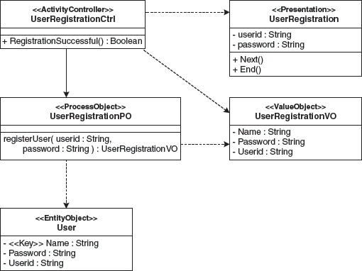
The domain-related meaning of this model is clear: The class UserRegistrationCtrl, being one step in the control flow, is able to activate a presentation in which a user’s ID and password can be entered and committed to the system. For authentication against the system, the controller uses the service userRegistration() of UserRegistrationPO.
The ProcessObject gets the entity representing the user based on the user ID, which constitutes the user’s identifying characteristic, and validates the supplied password. If registration is successful, the service issues the controller a UserRegistrationVO with the respective access data.
For modeling purposes, a design language is used that captures the architectural concepts used in the application. The focus of this design language is on architectural reusability, and results in an architecture-centric design, completely abstracting from technological details. The model can be transformed into source code for various target platforms via suitable rules.
We have already familiarized ourselves with the most important elements of the UML profile in the left column of Figure 3.3. The transformations in the generator are used to achieve the binding to the platform used in the car-sharing application, shown in the right column of Figure 3.3.
Figure 3.8 shows a section of the formal UML profile definition:
Figure 3.8 UML profile definition for the design language.

This profile represents a specialization of the standard UML metamodel (Chapter 6) on the class, attribute, and operation level, leading to a special language profile for the specific requirements found in the car-sharing’s application three-tier architecture.
The UML extension mechanism’s stereotype and tagged value are used here. For example, the classes that are assigned the stereotype «Presentation», such as UserRegistration, are responsible for the presentation and input of data. Classes labeled «EntityObject», such as User, constitute the application’s persistent business data types, and offer mechanisms for identification and querying. Design constraints (modeling rules) are also an important part of the profile, and can be formulated with the help of the Object Constraint Language.
Ideally, the profile definition, including the constraints, would take place in the UML tool and also be interpreted by it, so that exactly those tagged values defined for a certain stereotype are allowed, and the modeling rules (constraints) of the profile are checked. Unfortunately, many commonly-used UML tools do not yet possess these features, so that the formal UML profile definition still has the character of documentation.
3.2.2 Transformations
After we have defined a UML profile, we can now tackle the actual code generation. This is not a simple task. Fortunately, some partial tasks are of a more general nature, and there are MDSD tools that will do the work for us. This includes the neutralization of the UML tool’s XMI output, template expansion control, input/output stream handling, and scanning and persistence of protected code regions for business logic implementation. Most MDSD generators are frameworks and use a template language to describe transformations from model to code in a straightforward way.
Using XSLT in this context, one very soon realizes its limitations, particularly when the style sheet directly transforms the UML tool’s XMI output. Here, the XMI structures are so deeply entangled and indirectly referenced that XSLT stylesheets very soon become incomprehensible and therefore unmaintainable. The power of a programming language is also missing, and even protected code segments are difficult to realize and unwieldy. Sadly, no standard for MDA (or MDSD) generators or transformations is currently in existence, so the market offers many different approaches with various features. In the following sections we use the Open Source generator framework openArchitectureWare and the car-sharing example to demonstrate how metaprogramming in the context of the generative software architecture works in detail.
Metamodel/Profile Implementation
To enable the generator framework to generate the implementation skeleton for the target platform, it requires a Java implementation of the applied UML profile (see Section 3.2.3). The openArchitectureWare framework makes dealing with this task much easier, as it features a Java implementation of the UML class diagram and activity diagram elements that can be specialized via Java inheritance. Hence we must create a Java class of the same name for each stereotype in the profile, which in turn must inherit from the metaclass to which the respective stereotype will be applied, for example:
public class EntityObject extends Class
{}
public class Key extends Attribute
{}
Class and Attribute are not classes from the java.lang.reflect package, but – as already stated – metaclasses supplied by the openArchitectureWare framework.
The generator framework can instantiate this specialized metamodel – at the beginning of a generator run, it creates an instance of the metaclass EntityObject for each model element that has the «EntityObject» stereotype. Each single element of the input design model (classes, associations, attributes, operations, parameter, activities, transitions) is exactly represented by a Java object of the respective type in the generator’s JVM. Non-stereotyped elements will, of course, lead to the instantiation of the corresponding UML metaclass. As a consequence, the metamodel implementation will be instantiated that is, a design model will be transformed into a Java object graph that is ready to be accessed by the generator templates.
Besides the representation of stereotypes, the specialized classes have other important tasks in openArchitectureWare:
- Tagged values. A stereotype-specific tagged value in the UML profile is simply mapped to a string attribute of the same name of the corresponding Java metaclass.
- Service methods for generation. To simplify template programming and to prevent the template language from becoming a full-blown programming language, helper methods needed for code generation are programmed in Java as public methods of metaclasses. These can then be called from the templates as metaclass properties.
The following listing shows this next step5:
public class EntityObject extends Class
{
  /** set contains all Key-attributes of this EntityObject */
  protected ElementSet KeyList = null;
  /** returns set with all Key-attributes of this EntityObject */
  public ElementSet Key() throws DesignException
  {
    if (KeyList == null) {
      KeyList = new ElementSet();
      for (int i=0; i < Attribute.size(); i++){
       if (Attribute().get(i) instanceof Key) {
        KeyList.add(Attribute().get(i));
       }
      }
     }
     return KeyList;
    }
}
Attribute is inherited from Class here and constitutes the Java representation of the meta-relationship between classes and their attributes: in other words, you can learn which attributes the designer has modeled on the current Class via this API.
The template language of openArchitectureWare does not differentiate between access to attributes and access to methods of a metaclass – they are just properties. Methods hide attributes of the same name. The Key property defined here returns all of the EntityObject’s attributes that have the stereotype «key» applied to them. This allows elegant generation of the PrimaryKey class in the template, for example.
If the UML tool used does not support design constraints, they can be specified in the metamodel implementation: the generator automatically calls the respective operation prior to actual generation. After instantiation of the metamodel implementation, the generator tests all constraints by calling the CheckConstraints() operation of all model elements. As you can see in the next listing, this is how it can be ensured that, for each EntityObject, at least one Key is defined.
// EntityObject.CheckConstraints() defines the
// DesignConstraints for Elements with
// stereotype <<EntityObject>>
public String CheckConstraints() throws DesignException {
  if(Key().isEmpty())
    throw new DesignException(“Constraint violation:
        “+No Key found for EntityObject ‘” +
        this.Name() + “’”);
    return “”;
}
In case of a modeling error, descriptive error reports are created instead of an incomprehensible generator exception. This sort of feature is indispensable for productive use of MDSD in real-life projects.
Template Programming
The platform-specific implementation skeleton is generated by templates. Templates are very similar to generated code and can therefore be derived easily from a reference implementation. When templates are created, the constant parts of the reference implementation are copied into the template definitions as plain text and – with the aid of the template language’s control structures – combined with the properties read from the metamodel. In this way, for example, all classes and descriptors of the car-sharing application’s EntityBeans, with their properties for deployment, persistence, and relationships, are completely generated from classes labeled EntityObject, except for the EQLs for business logic-related finders.
We use the template for the generation of the naming entry for an Entity Bean in the platform-specific deployment descriptor jbossDD.xml as a simple example here:
«DEFINE DeplDescr FOR EntityObject»
  «FILE FullPathName“/“Name“jbossDD.xml”»
   <entity>
    <ejb-name>«Name»EJB</ejb-name>
    «IF needsRemote»
      <jndi-name>
        «FullPackageName».«Name»RemoteHome
      </jndi-name>
    «ENDIF»
    <local-jndi-name>
      «FullPackageName».«Name»Home
    </local-jndi-name>
   </entity>
  «ENDFILE»
«ENDDEFINE»
The output for the User class from our sample is written to the file UserjbossDD.xml and looks like this:
<entity>
    <ejb-name>UserEJB</ejb-name>
    <local-jndi-name>
      de.amg.carsharing.user.entity.UserHome
    </local-jndi-name>
</entity>
This brief template example already hints at the simplicity and conciseness of the template language. Only the identifiers in uppercase are elements of the template language. The other identifiers inside the «» brackets are properties of the metamodel. The remainder are expanded into the target file as static text strings. The section of the metamodel implemented in Java that is relevant for this template is shown in Figure 3.9:
Figure 3.9 The relevant section of the metamodel implemented in Java.

The class EntityObject corresponds with the design language’s stereotype of the same name. The other classes are part of the core metamodel of class diagrams (see Section 3.2.3). The design of the example in Figure 3.7 would deliver exactly one instance of the class EntityObject. The entity instance with the name User would have three associated attribute instances with the names Name, Password and UserID.
The set property Key provides, as we have seen, a collection of key instances of the associated attributes. The Boolean property needsRemote lets you inquire whether the entity is callable remotely, in which case corresponding remote interfaces must be generated for the existing platform. The string properties of the super class JavaObject, FullPackageName and FullPathName, traverse the design’s package hierarchy and return target language-conforming strings for the generation of Java import statements or file names, including their paths. Viewed from the template’s perspective, these are reusable services. The new super class has been inserted because the properties not only make sense for EntityObject, but also for ProcessObject, Value Object and other metaclasses. However, it is abstract and therefore cannot be instantiated directly.
Even this small example proves that metamodels are actually a pivotal issue in MDSD. For this reason, we have dedicated the whole of Chapter 6 to it.
The DeplDescr template is defined in a special template file, a simple text file with the suffix .tpl, with the aid of a DEFINE block (DEFINE … ENDDEFINE). It relates to a class of the metamodel (EntityObject) via FOR EntityObject. When a property is accessed, Java-side inheritance can be used so that all properties (for example FullPackageName) of JavaObject and its super classes Class, Type and Element are at its disposal.
The FILE block (FILE … ENDFILE) enables direct expansion of templates into a file, while the file name in the example is created dynamically through a combination of string properties and string constants. In the metamodel implementation, FullPathName is a method, and Name is an attribute.
Conditional expansion of parts of the template is supported via the IF … ENDIF block. For our example this means that either a remote or a local home interface can be generated alternatively into the jboss.xml deployment descriptor.
A particularly useful feature of this template language is its support of polymorphism: at generator runtime, template definitions of the same name are bound via the dynamic type of the model element, similar to methods in Java. This is one of the most important OO concepts and serves to avoid ‘type switches’ (using instanceof) that are hard to maintain and often distributed all over the code.
The entire template language of the openArchitectureWare framework consists of less than thirty constructs.
3.2.3 The Mode of Operation of the MDSD Generator
Figure 3.10 shows how the openArchitectureWare framework processes a generative software architecture.
Figure 3.10 How the openArchitectureWare framework works.

The components and their purposes are as follows:
- The generative software architecture contains all the necessary modules for use by the generator.
- Design language. A UML profile is often used as the design language: stereotypes, tagged values, and constraints serve to extend the standard UML with domain-specific concepts6.
- UML design. The UML design is the model of a concrete application of the software system family. The design language is used for modeling.
- XMI input. The UML design is exported to an XMI representation via the modeling tool. The design’s XMI representation can be processed by the generator. Each model element must be assigned a UUID (universally unique ID).
- Metamodel implementation (in Java). The MDSD generator features a freely-configurable metamodel. This is implemented in Java, which means that precisely one Java class exists in the metamodel for each standard UML element and for each stereotype in the design language. This enables the generator framework’s instantiator to use the XMI input information to instantiate the metamodel using reflection APIs. For this purpose, it uses an instantiation rule that defines which XMI element is mapped to which metamodel class. From this point on, the UML design is available as a Java object graph in the heap of the generator’s JVM. The objects of this graph are simply instances of the metamodel’s classes: this technique is comparable to the DOM tree that is instantiated when XML documents are parsed – compiler builders speak of an ‘abstract syntax’. The instantiated metamodel constitutes the generator backend interface and shields the templates from the complex XMI structures. At the same time, it supports the Java-based development of helper methods for the generation and testing of the modeling rules of the UML profile.
- Templates. The openArchitectureWare framework uses a template language that, together with the metamodel implemented in Java, constitute an object-oriented generator: the metamodel’s constructs translate themselves. The template language allows a simple and elegant formulation of the desired transformations based on the metamodel – see the examples in this section. The templates are dynamically connected with the instantiated Java metamodel via the generator backend and control the actual source code generation.
- Generator backend. The backend interprets the templates and performs the file handling, as well as the scanning of protected regions and the preservation of contents, the existing manually-written code, in the newly generated skeleton. To ensure that nothing gets lost, for example when renaming classes in the design, the generator uses the UUIDs in the XMI representation to identify the protected regions.
- Instantiation rule. This generator allows the mapping between XMI representation and metamodel to be defined in the form of a XML file. Thus XMI formats, for example from different UML tools, and the metamodel can vary independently of each other. In principle, it is even possible to process non-UML XML inputs. Due to the abstract syntax concept (the metamodel), the templates are not affected by a change of the concrete input format. • Runtime system. Logically, the runtime system or the platform are part of the generative software architecture, since it does not depend on a concrete application. However, each generated application uses the runtime system. In other words: the generated code – method calls, extends or implements relationships and so on – depends on the platform.
A more elaborate version of this process is described in Section 11.1.2.
3.2.4 Bootstrapping
Some kind of bootstrapping process is required to create the metamodels, templates, and profiles described above initially. It is not sensible – and difficult – to begin a project with the development of the templates before a target software architecture is present. Instead, the code to be generated later should be ‘handmade’ first, to act as a blueprint from which the templates will subsequently be extracted. A runnable reference implementation provides the basis for this. Static code fragments can be transferred to the templates one for one. The variable parts of the code are worked out with the help of the template language based on the metamodel. Thus the creation of templates becomes a task that deals essentially with the elegant replacement of text, and no longer with the definition of architectural concepts. This differentiation simplifies the execution of both subtasks.
Chapter 13 details the process-related aspects of Model-Driven Software Development further.
3.2.5 Adaptations of the Generative Software Architecture
Changes and extensions to the functional requirements will be necessary in the course of an application’s lifecycle, but requirements relating to architectural aspects of the application will also change, for example due to the software’s use on a different application server, or migration to a new version of EJB or Struts. Whereas in a non model-driven scenario all affected classes must be manually adapted, the use of an MDSD generator allows these changes to be made in one place only. The transformation is adapted accordingly in the templates, and the new infrastructure code is regenerated. Manual adaptations are required exclusively in the protected regions of the source code, and only if the structural change affects the programming model – that is, the way in which the manually-developed code interacts with the generated code.
Even a small excerpt from the example used here demonstrates clearly how the developer’s work can be simplified. If the structure of descriptors changes because of a new version of the EJB component model, or because another application server is used, only the template shown below needs to be adapted, rather than all of the application’s *jbossDD.xml files for all EntityObject classes. If we assume a migration of the JBoss container to the container of a Bea Web-logic server, for example, the «EntityObject» User in our example would require, among other things, the following descriptor:
<weblogic-enterprise-bean>
   <ejb-name>UserEJB</ejb-name>
  <entity-descriptor>
   <persistence>
    <persistence-use>
     <type-identifier>
      WebLogic_CMP_RDBMS
    </type-identifier>
    <type-version>6.0</type-version>
    <type-storage>
       META-INF/weblogic-cmp-rdbms-jar.xml
     </type-storage>
    </persistence-use>
   </persistence>
  </entity-descriptor>
  <local-jndi-name>
    de.amg.carsharing.user.entity.UserHome
  </local-jndi-name>
</weblogic-enterprise-bean>
To propagate these changes for all classes of type EntityObject, we change the template for the generation of the descriptor files as described in the following listing, then re-run the generator.
<<DEFINE DeplDescr FOR EntityObject>>
<<FILE FullPathName“/“Name“weblogic-ejb-jarDD.xml”>>
  <weblogic-enterprise-bean>
   <ejb-name><<Name>>EJB</ejb-name>
      <entity-descriptor>
   <persistence>
    <persistence-use>
     <type-identifier>
      WebLogic_CMP_RDBMS
     </type-identifier>
     <type-version>6.0</type-version>
            <type-storage>
      META-INF/weblogic-cmp-rdbms-jar.xml
     </type-storage>
    </persistence-use>
   </persistence>
     </entity-descriptor>
  <<IF needsRemote>>
   <jndi-name>
      <<FullPackageName>>.<<Name>>RemoteHome
    </jndi-name>
  <<ENDIF>>
  <local-jndi-name>
    <<FullPackageName>>.<<Name>>Home
  </local-jndi-name>
 </weblogic-enterprise-bean>
<<ENDFILE>>
<<ENDDEFINE>>
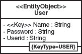
The architectural aspects’ requirements can not only necessitate changes to existing structures, but can also require extensions. To explain the necessary steps for the extension of a generative software architecture, a tagged value for business classes should be introduced. This tagged value should be labeled KeyType and can either have the value USER or SYSTEM. Via KeyType, the type of the business class’ unique key can be determined. In the case of KeyType==SYSTEM an attribute and a unique key are generated, otherwise, for KeyType == USER, the key is determined through identification of an attribute with the stereotype «Key». In the example provided in Figure 3.11, the business class User possesses the KeyType == USER and the attribute Name labeled as «Key».
Figure 3.11 Extended EntityObject User.
Due to the extension of the profile element «EntityObject», the modeling constraint must be adapted accordingly: «Key» attributes must and may only be defined in the case of KeyType == USER. Figure 3.12 shows the respectively adapted formal profile definition with tagged value and OCL constraint.
Figure 3.12 Profile definition with constraints.

In our generative software architecture’s implementation, the metamodel’s tagged value is introduced into the class EntityObject as a property, which is set by the generator framework during instantiation of the metamodel. Thus the implementation of the CheckConstraints() method must be extended respectively:
public class EntityObject extends JavaObject {
  public String KeyType = “USER”; //TaggedValue Default
  …

  // EntityObject.CheckConstraints()
  // defines the DesignConstraints for
  // Elements with stereotype <<EntityObject>>
  public String CheckConstraints()throws DesignException {
    if( Key().isEmpty() &&
      KeyType.equals(“USER”)) {
     throw new DesignException(“Constraint “+
        +“violation: No Key found for “+
        +“EntityObject ‘” + this.Name() + “’”);
     }
    return “”;
  }
  …
}
The higher expressive power of the UML profile is also reflected by the templates. Here, the following transformations must take place, depending on the KeyType, as indicated below for the Entity Bean class:
<<IF KeyType == “SYSTEM”>>
  // init-method
  private void init() {
    long time;
    time = System.currentTimeMillis();
    setImplId(String.valueOf(time) + “+” +
            System.identityHashCode(this));
  }
  public <<Name>>PK ejbCreate() throws CreateException {
    init();
    …
<<ELSE>><<REM KeyType==“USER”>>
  public <<Name>>PK ejbCreate(
      <<EXPAND Attribute::Signature FOREACH Key
                  USING SEPARATOR “, “>>)
      throws CreateException {
    <<FOREACH Key AS CurKey EXPAND USING SEPARATOR “
”>>
     setImpl<<CurKey>>(<<CurKey.asPARA>>);
    <<ENDFOREACH>>
    …
<<ENDIF>>
You can see what the generated Entity Bean class looks like in the implementation directly from the template. Depending on the KeyType, either the «Key» attributes will be set in the constructor, or a system-side ID is assigned.
As we have shown, changes and extensions of architectural aspects need only be made in a single place in the generative software architecture, rather than in many distributed places in the applications’ code.
3.2.6 The Boundary of Infrastructure Code
Up to this point we have shown which tasks must be taken on in the context of architecture development and how the infrastructure code is defined. But how can the manually-developed code – typically, the business logic – be implemented within this skeleton, and how can we maintain it if iterative regeneration and structural changes occur? There are various approaches to the integration of generated infrastructure code and manually-written business code, and we expand on these in Chapter 9.
The MDSD generator used in this example supports protected regions: that is, it is possible to designate certain areas of code in which developers implement the business logic. To preserve the code during regeneration, it is necessary to mark these areas as unique. To this end, the relevant protected regions are assigned unique, constant IDs from the model, the UUIDs from the UML tools’ XMI output. The definition of a protected region of the template might look like this:
<<PROTECT CSTART “//” CEND “” ID Id“Operation_MethodBody”>>
  //add custom initialization here …
<<ENDPROTECT>>
This leads to the following generator output:
  // PROTECTED REGION ID(12aaaeOperation_MethodBody) START
   ReservationParameterValueObject vo = null;
   try {
    CarSharingAutoModuleComponent component =
      new CarSharingModuleComponentImpl();
    …
  } catch ( … ) { … }
  return vo;
// PROTECTED REGION END
3.2.7 Structuring Metaprograms
The templates introduced here – together with the properties of the metamodel implemented in Java – constitute one possible implementation technique for MDSD transformations, in this case distributed across two languages. We are effectively dealing with metaprograms here, since they serve the creation of programs. It should be kept in mind, however, that metaprograms are programs too. This means that on this (meta-)level software is also created in real-life projects – software that must be structured so that it can grow iteratively and incrementally.
Here, mechanisms such as those we know from object-orientation are required. For example, construction of components is desirable. There might for example be a need to switch the component for the generation of the Entity layer to facilitate a migration from EJB 1.1 to EJB 2.0. Inheritance and polymorphism are useful allies here too. The availability of such features says a lot about how good your MDSD tool really is.
More information on this topic can be found in Chapter 11, as well as in the second case study in Chapter 16.
3.3 Conclusion and Outlook
The practicability of the OMG–MDA approach is often partially met with skepticism, which may not be totally unfounded. There are quite a few people who consider MDA to be merely a ‘discipline for theorists’. However, the pragmatic version of architecture-centric MDSD introduced here has proved its practical value over many years and in projects of differing scope and size, and early adopters have come to use this approach productively.
Some think the introduction of generative approaches will limit their personal freedom, or they fear being locked in by the generator supplier. Such prejudices typically emerge due to bad experiences with CASE approaches, or through missing or bad information. The approach itself does not require the assignment of roles to specific people, it merely describes the tasks that come with certain roles, such as developer and architect. The allocation of roles is the sole responsibility of the team or project management.
Besides a suitable methodology, the availability of tools that support realization of the required concepts is significant for the successful use of AC-MDSD. In our view, this support is not yet optimal. Better support on the UML tool side through distributed modeling, profiling, generator integration and OCL constraint support on the metalevel are particularly desirable. However, there are promising attempts to provide for example debugging or traceability at the metalevel as part of MDSD generators.
Architecture-centric MDSD is not the only MDSD variant. For example, profiles for business-related domains focus on much narrower application domains, yet their generation potential is usually much higher (often 100%). We deal with this more comprehensive topic in the remaining parts of this book. However, we want to point out that the tools introduced in this chapter can also be used for this purpose, especially as they do not depend on a concrete domain.
1 XMI: XML Metadata Interchange. A MOF–XML mapping that is used mostly to serialize UML models in XML form. Almost all UML tools support XMI.
2 Universal unique identifiers for model elements.
3 OCL: Object Constraint Language, part of UML.
4 The config.xml file is used to configure pages and page flow in the Struts framework.
5 For common constraints, for example like those in the following listing, openArchitectureWare offers predefined helper functions. To keep our example simple, we do not use these here. The second case study in Chapter 16 illustrates this approach.
6 Any other modeling languages can also be used.