Chapter 2
MDSD – Basic Ideas and Terminology
This chapter introduces the most important basic concepts of Model-Driven Software Development, as well as the motivation for them. We prefer the abbreviation MDSD for Model-Driven Software Development over the less-precise variant ‘MDD’ (Model Driven Development). The first abbreviation has become more popular in the software modeling community over the past two years.
The Object Management Group’s Model Driven Architecture (MDA) is both a flavor and a standardization initiative for this approach. Our focus here is its practicability in software projects. In many respects our concepts and experiences are congruent with those of OMG’s MDA vision, but in other respects they differ. We point out the latter and discuss them. Apart from this, the MDA terminology, due to its standardization and pervasiveness, is extremely useful for providing an introduction to this topic, and this is exactly how you should approach the second part of this chapter: MDA provides the basic terminology for MDSD. The chapter’s third part introduces the concepts that have been missing until then and which are required to understand the case study.
2.1 The Challenge
In the twenty-first century software is all around us. The software industry has become one of the largest on the planet, and many of today’s most successful businesses are software production companies or offer services in the software field.
Software is today a relevant part of the machinery of all technology-based and many service-based businesses. High software development costs have significant economic impact, and bad software design, which impairs the productivity of users, can have even more serious consequences.
Many manufacturers of business software are so involved in dealing with the constantly-changing implementation technologies that productivity effort and risk management fall behind. Neither off-shoring, nor the newest generation of infrastructure software such as integrated development environments (IDEs), EAI1 or BPM2 tools and middleware, are much use here. In most cases, productivity problems are the result either of insufficient consistency or openness in the application architecture, or of inadequate management or dependencies between various software components and unsuitable software development processes.
2.1.1 Historical View
The nineteen-nineties were mainly influenced by two software development paradigms. At the beginning of the nineties, these were Computer Aided Software Engineering (CASE) and fourth-generation languages (4GLs). In the second half of that decade, Object-Orientation entered the mainstream.
CASE methods and the corresponding tools were expensive, and proprietary approaches collided with a growing awareness of open standards. Many companies had bad experiences with some manufacturers, so eventually not only the tools but also the model-based software development approach were dumped. Object-orientation did not keep all of its promises, but it did become the foundation of component technologies, and object-oriented languages successfully replaced the previous generation of programming languages.
With the departure of 4GLs and CASE, OO modeling tools became the center of tool manufacturers’ attention, resulting in the Unified Modeling Language (UML) notation standard and in tools based on a ‘round-trip’ philosophy. This enables smooth switching between UML models and the corresponding implementation code. Superficially, UML tools impress with their ability to keep models and code synchronized. However, on closer inspection one finds that such tools do not immediately increase productivity, but are at best an efficient method for generating good-looking documentation3. They can also help in understanding large amounts of existing code.
2.1.2 The Status Quo
The boundaries between modern UML tools and Integrated Development Environments (IDEs) are disappearing. For example, some UML tools have ‘comfortable’ code editors and integrated compilers, while traditional IDEs are equipped with UML modeling components. Software development tools, meanwhile, provide increasingly smart wizards that support users in the application of design patterns, the creation of user interfaces, and the generation of code skeletons for use with popular frameworks.
Although this approach constitutes an improvement compared to older UML tools that were only able to generate empty class skeletons, they strongly resemble CASE tools, as they are similarly inflexible. If, for example, a design pattern changes, today’s UML tools are unable to transfer the effects automatically and iteratively to the source code of an application system without losing the abstraction.
Eventually, the weaknesses of mainstream IDEs and UML tools led to the formation of the OMG’s MDA initiative. Appropriate tools allow users to define precisely how UML models are to be mapped to combinations of company-specific implementation technology. Unfortunately, in this context some traditional CASE tool manufacturers have spotted a second opportunity to offer their tools in a new package, as commercial MDA products. The tools cannot however be customized to meet individual requirements or customer needs, as they still adhere to the ‘one size fits all’ dogma. Most tools listed on the OMG’s Web pages, however, actually deserve the label ‘MDA tool’. In parallel with the progress in the field of software development tools, a significant evolution has also taken place in the field of software development methods, which has hardly been addressed yet in MDA.
The rapid adoption of agile approaches demonstrates an increasing resistance to traditional software development methods, which usually require a large amount of manually-created prose text documents. Today it is openly acknowledged that traditional methods required the production of such documentation, but in practice this cannot be reconciled with the market’s demand for lower software development costs. Admittedly, agile methods such as Extreme Programming (XP) [Bec00] alone do not offer sufficient guidance for the creation of high quality software, and they do not scale to more complex projects. The odd misbelief that they can compensate for a development team’s lack of analytical abilities or software design experience is particularly problematic.
2.2 The Goals of MDSD
Before we proceed to discuss the concepts and terminology of MDSD, we want to make a few comments on the goals of MDSD. However, we can only touch on how these can be achieved here.
- MDSD lets you increase your development speed. This is achieved through automation: runnable code can be generated from formal models using one or more transformation steps.
- The use of automated transformations and formally-defined modeling languages lets you enhance software quality, particularly since a software architecture – once it has been defined – will recur uniformly in an implementation.
- Cross-cutting4 implementation aspects can be changed in one place, for example in the transformation rules. The same is true for fixing bugs in generated code. This Separation of Concerns [Lad03] promises, among other things, better maintainability of software systems through redundancy avoidance and manageability of technological changes.
- Once they have been defined, architectures, modeling languages and transformations can be used in the sense of a software production line for the manufacture of diverse software systems. This leads to a higher level of reusability and makes expert knowledge widely available in software form.
- Another significant potential is the improved manageability of complexity through abstraction. The modeling languages enable ‘programming’ or configuration on a more abstract level. For this purpose, the models must ideally be described using a problem-oriented modeling language.
- MDSD offers a productive environment in the technology, engineering, and management fields through its use of process building blocks and best practices. It thus contributes to meeting the goals described here.
- Finally, based on the OMG’s focus and history, the organization’s primary motivations for MDA are interoperability (manufacturer-independence through standardization) and portability (platform-independence) of software systems. These goals that can be met only if a standardization – such as the OMG’s MDA effort – is achieved. The same motivation has already led to the definition of CORBA5. To achieve these goals, the OMG aims at separating the specification of a specific functionality from its implementation on a specific platform. The MDA serves the purpose of providing guidelines and standards that should lead to a corresponding structuring of system specifications in the form of models.
Most of the goals presented here are not new. On the contrary, they represent something like the IT industry’s ‘Holy Grail’: no-one is inclined to believe in beneficial promises anymore, and rightly so. But if you take a look at the history of IT or computer science, you can see that an ongoing evolution is taking place. High-level languages, object-orientation and component systems were milestones on the road toward meeting these goals – and MDSD is another. This paradigm takes us a small – or even a big – step closer to these goals.
2.3 The MDSD Approach
Each software has its inherent construction paradigms, expressed in the source code – an inner structure. How sound and how pronounced this structure is directly influences development speed, quality, performance, maintainability, interoperability, and portability of the software. Those are extremely important key economic factors.
The problem is that it is difficult to recognize the actual construction paradigms on a programming language level, because their abstraction level is much lower. To put it differently, the much-treasured inner structure is present in a cloudy, distributed, and of course also a strongly individualized form. It is no longer directly represented in the system itself. Its quality varies, depending on the skills and interpretation of the developers.
The idea of modeling is not exactly new, and is used mostly for sophisticated development processes to document a software’s inner structure. Developers then try to counteract the inevitable consistency problems with time-consuming reviews. In practice, these reviews and also the models are among the first victims when time presses - from a pragmatic point of view, even rightly so. Another approach is ‘round-trip’ or reverse engineering, which most UML tools offer, which is merely source code visualization in UML syntax: that is, the abstraction level of these models is the same as for the source code itself6. Visually it may be clearer, but the essential problem remains the same.
Model-Driven Software Development offers a significantly more effective approach: Models are abstract and formal at the same time. Abstractness does not stand for vagueness here, but for compactness and a reduction to the essence. MDSD models have the exact meaning of program code in the sense that the bulk of the final implementation, not just class and method skeletons, can be generated from them. In this case, models are no longer only documentation, but parts of the software, constituting a decisive factor in increasing both the speed and quality of software development. We emphasize ‘model-driven’ as opposed to ‘model-based’ to verbally highlight this distinction.
The means of expression used by models is geared toward the respective domain’s problem space, thus enabling abstraction from the programming language level and allowing the corresponding compactness. All model-driven approaches have this principle in common, regardless of whether the domain is labeled ‘software architecture’, ‘financial service systems’, ‘insurances’, or ‘embedded systems’. To formalize these models, a higher-level Domain-Specific Modeling Language (DSL) is required. From this ‘bird’s eye view’, it doesn’t matter whether this is a UML-based language or not.
Besides formal and abstract models, ‘semantically rich’, domain-specific platforms make up the second foundation pillar: prefabricated, reusable components and frameworks offer a much more powerful basis than a ‘naked’ programming language or a technical platform like J2EE. First and foremost, this means that the generator, which is supposed to transform the formal model, will be simplified once the generated code can rest on APIs of significantly higher quality. The introduction of reusable frameworks, super classes, and components to avoid code redundancy is not a new idea, but in the context of MDSD they serve additionally to intercept the model transformation half-way in the form of a well-formed platform, which causes a significant complexity reduction of the code generators7.
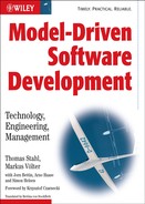
Figure 2.1 shows the relationships in application development with MDSD.
Figure 2.1 The basic ideas behind Model-Driven Software Development.

Let’s take a look at an existing application or a reference implementation (the upper left corner of the diagram). These are unique items with individual structures. We can restructure the code of these application in our minds so that three parts can be separated8 (the lower left corner): a generic part that is identical for all future applications, a schematic part that is not identical for all applications, but possesses the same systematics (for example, based on the same design patterns), and finally an application-specific part that cannot be generalized. At this point, we won’t make any statements about the significance of each part: in extreme cases, the application-specific part can even be empty. Model-Driven Software Development aims to derive the schematic part from an application model. Intermediate stages can occur during transformation, but in any case DSL, transformation, and platform will constitute the key elements. They must only be created once for each domain, for example ‘enterprise software architecture’ or ‘inventory system for insurance’ (lower right).
2.4 Basic Terminology
This section introduces the most important concepts and terms of the MDA standard, to establish the basic terminology for MDSD.
Domain-related specifications are defined in Platform-Independent Models (PIMs). To this end, a formal modeling language is used that is specific to the concepts of the domain to be modeled. In most cases, one would use UML that has been adapted via profiles to the respective domain, not least because of its tool support (see Section 6.5). These domain-specific descriptions are completely independent of the later implementation on the target platform. Such target platforms can be, for example, CORBA, J2EE, .NET or proprietary frameworks/platforms. Figure 2.2 illustrates this basic principle.
Figure 2.2 The basic principle of MDA.

Via model transformation, usually automated with tools, Platform-Specific Models (PSMs) are created from the Platform-Independent Models. These Platform-Specific Models contain the target platform’s specific concepts. The implementation for a concrete target platform is then generated with another tool-supported transformation based on one or more PSMs (see Figure 2.3).
Figure 2.3 PIM, PSM and transformation.

It is important to note that a PIM and a PSM are relative concepts – relative to the platform. In the example shown above, the EJB-PSM is specific to the EJB 2.0 platform, yet it is independent regarding its concrete, application server-specific realization.
Let’s look at another example. Figure 2.4 shows a small part of a PIM. It shows a class model with two domain classes: Customer and Account. Both classes have the «Business Entity» stereotype, and both have an attribute that is assigned the stereotype «UniqueID». The method findByLastName features the stereotype «Query» under Customer.
Figure 2.4 An example that illustrates the relationship between PIM, PSM and code.

The annotation of stereotypes on UML model elements allows us to change or specify the meaning of an element. A class with the stereotype «Business Entity» is not just a simple class, but is rather a self-contained entity in business applications. What this means in practice is determined by transformations that define how a stereotype such as «Business Entity», for example, is mapped to an existing platform such as J2EE.
Such an extension of the standard language vocabulary of UML through stereotypes is called a (UML) profile. It is a standard mechanism specified by the OMG to ensure openness, and is used here to define a formal modeling language. This formalization is mandatory for transforming a UML model into an MDA model. The concepts «Business Entity», «UniqueID», and «Query» are completely independent of the target platform. Dependency occurs through the transformation from PIM to PSM. Here, we find the stereotypes that are specific to J2EE: «EJBEntityBean», «PrimaryKeyField», and «EJBFinderMethod». These are also originally concepts that acquire their meaning through transformations, in this case transformations into the Java programming language.
The transformation eventually turns the PSM into source code, in which the concepts described here can be found in their concrete manifestation.
2.4.1 An Overview of MDA Concepts
The Model
A model is an abstract representation of a system’s structure, function or behavior. MDA models are usually defined in UML9. In principle, the MDA formally considers even classic programming languages as MDA modeling languages that in turn maintain relationships with a platform. Without a doubt this is correct, but we think that this approach occasionally hampers the elucidation of concepts, so from now on we will keep the terms model and modeling language clearly separate from the terms program and programming language.
UML models are not per se MDA models. The most important difference between common UML models (for example analysis models) and MDA models is that the meaning (semantics) of MDA models is defined formally. This is guaranteed through the use of a corresponding modeling language which that is typically realized by a UML profile and its associated transformation rules. We discuss these mechanisms in greater detail later in this chapter. All in all, this means that the mapping of a model to an existing platform is clearly defined.
The Platform
At first the MDA says nothing about the abstraction level of platforms. Platforms can build on each other, for example an Intel PC is a platform for Linux. Similarly, CORBA, J2EE, or Web Services are possible platforms for an e-business system, and C++ is a possible platform for CORBA. A well-defined application architecture, including its runtime system, can also be a platform for applications. We consider the latter idea to be one of the key concepts for Model-Driven Software Development and discuss it in greater detail later on.
UML Profiles
UML profiles are the standard mechanism for expanding the vocabulary of UML. They contain language concepts that are defined via basic UML constructs such as classes and associations, stereotypes, tagged values, and modeling rules (constraints) – see Figure 2.5.
Figure 2.5 Use of a UML profile.

A UML profile is defined as an extension of the UML metamodel. A metamodel defines, among other things, the basic constructs that may occur in a concrete model. Conceptually, a model is an instance of a metamodel. Accordingly, the UML metamodel contains elements such as Class, Operation, Attribute, or Association. The metamodel concept is one of the most significant concepts in the context of MDSD. For this reason, we dedicate a whole chapter to it, Chapter 6. However, at this stage we are content just to gain an intuitive understanding. The relationship between the metamodel and profile is clarified in Figure 2.6, using a simplified example – a UML profile for Enterprise Java Beans (EJB).
Figure 2.6 UML metamodel and UML profile for EJB (section of).

In the UML profile, the standard UML concepts Attribute, Class and Operation are supplemented by the specific concepts PrimaryKeyField, EJBEntityBean and EJBFinderMethod. In addition, a new UML 2.0 language construct, an extension, is used. This is indicated by the filled-in inheritance pointer. To avoid confusion, we made these larger.
Additional extensions are defined through tagged values and modeling guidelines in the form of constraints. A constraint is usually annotated as a comment for the respective model elements: we use the formal constraint language OCL here. Tagged values are rendered as attributes of the stereotype.
A UML profile therefore offers a concrete notation for referencing metamodels from a model, and determines whether a certain model is ‘well-formed’, that is, valid or not. In short, it defines a formal modeling language as an extension of UML.
Further details of these relationships are elaborated on in Chapter 6.
PIM and PSM
The separation of Platform-Independent Model (PIM) and Platform-Specific Model (PSM) is a key concept of the OMG’s MDA. The background to this is as follows: concepts are more stable than technologies, and formal models are potentially useful for automated transformations. The PIM abstracts from technological details, whereas the PSM uses the concepts of a platform to describe a system (see Figure 2.7). The reverse route – the extraction of a PIM from a PSM – is extremely hard to automate, and in some cases impossible. That usually requires manual, intellectual work, which is somewhat awkwardly termed Refactoring in the MDA specification. (The meaning of Refactoring leans more toward equivalence transformations – see [Fow99].)
Figure 2.7 The relationship between PIM, PSM and platform.

Transformations
Transformations map models to the respective next level, be it further models or source code. In terms of the MDA, transformations must be definable flexibly and formally based on an existing profile. This is a prerequisite for the desired automation of the transformation via generators.
Most of the currently-available MDA/MDSD tools define their transformation rules not between two metamodels, but instead for example use templates for the direct generation of source code, without the programming language’s metamodel being formally known to the generator. However, generators exist that attach the transformation rules to the UML profile or, respectively, its corresponding metamodel. Such approaches are absolutely workable in practice, and are described in Chapters 3 and 9. The advantage of a transformation based on two metamodels (source and target) is mostly the elegant mapping from one metamodel to another. We doubt whether this paradigm is feasible for the generation of source code in practice, however.
Current generators solve this problem in a different way, through the use of proprietary transformation languages. In this context, JPython, TCL, JSP, XSLT, or custom script/template languages are used10. The generator templates defined with these languages principally work like macros and use the models as input data. As a consequence, at present no interoperability for model transformations exists: standardization is on its way, however – see Section 10.5.
Chapter 12 provides a deeper insight into the MDA standard.
2.5 Architecture-Centric MDSD
In this section we want to supply the foundations that can enable you to understand the later case study: one flavor of MDSD that is termed Architecture-Centric MDSD (AC-MDSD). The approaches described here have evolved in the course of many years’ practical experience with many projects, and particularly focus on practical usability.
2.5.1 Motivation
In contrast to the primary goals of the OMG for MDA, interoperability and software portability, AC-MDSD aims at increasing development efficiency, software quality, and reusability. This especially means relieving the software developer from tedious and error-prone routine work. Today developers are confronted with extremely complex software infrastructures: application servers, databases, Open Source frameworks, protocols, interface technologies and so on, which all need be connected to create robust and maintainable high-performance software. Due to increasing complexity in this field, the discipline of software architecture assumes more and more importance.
The existence of a software infrastructure also implies the existence of corresponding infrastructure code in the software systems using it. This is source code, which mostly serves to establish the technical coupling between infrastructure and applications to facilitate the development of domain-specific code on top of it. The J2EE/EJB programming model is a prime example in this context: home and remote interfaces, Bean classes, descriptors – technical code that admittedly contains domain-related information such as method signatures, but which also exhibits a high degree of redundancy. After they have built four or five Enterprise Beans manually, if not before, a J2EE developer will long for a generator to create this type of infrastructure code – and can get this kind of support, typically in the shape of a preprocessor or an IDE wizard.
At best, some infrastructure components will bring their own ‘helpers’ for the generation of their own infrastructure code. The problem here is that these tools do not ‘know’ each other, which is why they fall short of the possibility of a holistic and architecture-centric approach, as we will see in the case study.
Ergo, the goal of AC-MDSD must be integrated automation of infrastructure code generation and, as a consequence, the minimization of redundant infrastructure code in application development.
When we talk about infrastructure code, we are not talking about peanuts: measurements [Chapter 18] show that between 60% and 70% of modern e-business applications typically consists of infrastructure code.
2.5.2 Generative Software Architectures
As the adjective architecture-centric already implies, software architecture plays the central role in the MDSD flavor discussed here. Actually, a holistic, generative approach for the creation of infrastructure code can only work on the basis of a thoroughly worked-out and formalized software architecture.
You can imagine this as follows: the more and the better a software architecture has been elucidated, the more schematic the source code of applications using this architecture will become. If the architecture’s definition consists only of slides representing the system infrastructure (databases, application server, mainframes, networks and so on) and maybe additionally the most important layers, it is likely that two developer teams will realize the same application in entirely different ways – including the implementation of the software architecture: two unique applications will be created.
If we assume however that a team of architects does some groundwork and develop some sort of technical reference implementation that shows the concrete realization of the most important software architectural aspects at the source code level, application developers can use this reference as a blueprint. Since the same technical realizations – notwithstanding domain variations – recur in development practice (for example use of a specific interface technology or an MVC pattern), the majority of the workload would be copy and paste programming. Of course, this sort of programming is much more efficient than individually thought-out code created from scratch.
In essence, the more of a software architecture’s definition has been fleshed out in source code, the more schematic and repetitive the application development process will become. Schematic programming means mostly copy and paste, followed by modifications that depend on the domain context. This part of the work is clearly non-intellectual. If we pursue this train of thought, it is not too far-fetched to leave the tedious and error-prone copy/paste/modify job to a generator, which ultimately leads to a generative software architecture. Here, all implementation details of the architecture’s definition – that is, all architectural schemata – are incorporated in software form. This requires a domain model of the application as its input, and as output it generates the complete infrastructure code of the application – the very code that otherwise would need to be generated via a tedious copy/paste/modify process. To this end, the model only needs to have specific annotations that reference the architectural concepts defined as part of the generative software architecture.
Usually an architecture-centric UML profile is used for modeling in AC-MDSD. Thus a formal, architecture-centric application design is created. The model-to-code transformations are defined typically in the form of generator templates, so that the complete infrastructure code can be generated automatically from the architecture-centric design model. It is important to note that the model must already contain all relevant information for the generation of the infrastructure code – it is just a lot more abstract and more compact than the expanded code. The templates can use the entire infrastructure’s power and base the generated code on this platform, as described in Section 2.3, simplifying the templates. Since the generation of the code is motivated by technical and architectural concerns, a ‘semantic gap’ remains: developers must manually create the application’s actual domain code, that is, the actual, domain-specific functionality that is not infrastructure code.
There are various techniques for the integration of generated and manually-created code. We look at them in detail in Chapter 8 and Chapter 9. Figure 2.8 illustrates these correlations. They are explained further in the next chapter’s case study, using a practice-oriented, realistic example.
Figure 2.8 The principle of architecture-centric MDSD.

A generative software architecture is a powerful means to achieve the goals we listed in Section 2.2. Its most important advantages are higher development speed and software quality, better maintainability, and practical reusability – reusability within one application, but of course even more beyond the boundaries of a single application. A generative software architecture can support an entire group or family of architecturally-similar applications – a software system family. In effect, AC-MDSD deals with the creation of generative software architectures for software system families, instead of creating unique products.
2.5.3 Architecture-Centric Design
The defined design language (typically a UML profile) contains the software system family’s architecture concepts in the shape of a ‘platform-independent’11 abstraction. Designers use this design language to create the domain’s application design in the form of PIMs. Other than when dealing with the OMG–MDA vision, they will in most cases deliberately forego the transformation of these PIMs into explicitly visible, platform-dependent UML models (PSMs) when working with AC-MDSD.
Practical project experience has hitherto proved that this simplification is usually more useful than the additional degrees of freedom gained with PSMs. As a consequence, one need not control, manipulate, and enrich the various intermediate transformation results with specific information12. This not only allows for a more efficient development, but also avoids potential consistency problems: a manual change of an intermediate model might result in an inconsistency with higher abstraction levels that is not automatically correctable.
Similarly, we forego reverse engineering from the source code to the PIM, which in general is not feasible anyway. A model that has been created ‘backwards’ from source code is naturally as little abstract as the source code itself. Only its presentation is different, perhaps providing better understandability for some purposes. For specific arbitrary sections of source code, a PIM from which the program could be derived via transformation13 may not exist – especially if the PIM modeling language focuses on a specific domain such as software architecture for e-business systems. In the context of MDA specifications, this fact is more or less ignored by the OMG however.
Some members of the MDSD tool-builders community anticipate tool-supported wizards or some similar solution that will at least enable semi-automated reverse engineering. In our opinion this is a concession rather than a goal-oriented concept14 – at least where newly developed software is concerned. Admittedly, this view may first be perceived as being disadvantageous, depending on your personal work preferences, but in truth it is an advantage, as we will learn later on. Basically, AC-MDSD builds on forward engineering.
This forward-engineering based, generative approach allows us to derive conclusions about generated applications from the ‘hard facts’ of architecture-centric models. A generative architecture can guarantee a loose coupling of components or the absence of access paths between different application layers. For example, it can ensure that a presentation layer, such as a Web user interface, cannot access a database’s SQL interface directly.
At this point it’s important to note that forward engineering is not to be mistaken for a waterfall approach to development. It merely means that design changes must be made to the model instead of the source code, which of course does not mean that the whole application must be modeled at once. We concede that forward engineering does not exclude such an approach, but this does not mean that it is mandatory. In fact, we favor an iterative, incremental process [Oes01].
Let’s now examine an example of such a PIM, shown in Figure 2.9. This model does not reveal anything about the technologies that were used – the technological realization of such models is defined only once it is mapped to a concrete platform. A formal UML design language is created through the semantic enrichment of the model with stereotypes, tagged values, and constraints. For AC-MDSD, the abstraction level of this language lies on the level of architectural concepts, which is why we speak of architecture-centric design. In other words: the domain of AC-MDSD is software architecture.
Figure 2.9 An example of architecture-centric design.

The domain-related meaning of the diagram in Figure 2.9 is fairly obvious: at its core is an activity, a module for superordinate process models that is able to carry out an action for the creation of a customer-specific account overview. The customer entity serves as input, which is transmitted to the activity. Besides two domain-related attributes, the customer entity possesses an identifying characteristic (a key) and is able to calculate the total balance by adding balances of the associated accounts. The activity, or respectively its action, uses a presentation with three domain-related attributes to display the result.
A standard Java code generator would ignore the annotated stereotypes and generate the signatures of four simple Java classes. In AC-MDSD, the realization of the model on the programming language side is realized by a mapping to a concrete platform. This is illustrated by the two examples that follow.
For an EJB-Based Architecture with HTML Clients
Activity classes are stateless session Beans that implement the interfaces of a server-side process engine. Each action is declaratively transactional. The entity classes are Beans with corresponding local interfaces. Attributes of the type key constitute the primary key classes. For public attributes, getter and setter methods are applied. Container Managed Persistence (CMP) is used for persistence. The necessary descriptors can be deduced from the model. For associations, access methods are available that are based on the associated model’s finder methods. The presentation classes specify JSP models that serve to fill JSP/HTML pages. The presentation implementations are activated by a FrontController framework.
For a C++/CORBA-Based Client-Server Architecture
For each activity class there is an IDL interface. All attribute and parameter types of the design are mapped to corresponding IDL types. A suitable C++ skeleton exists. The activity classes implement the interfaces to a specific workflow system. Actions (action operations) are transactions on an Object Transaction Monitor (OTM). All entity classes are non-distributable C++ classes: their instances are submitted to a RDBMS via object-relational mapping. Attributes of the type key serve as primary keys. The presentation classes are Java Swing GUIs that implement the interfaces of a specific client-framework.
By means of this simple example of a model we can easily recognize the main advantages of this approach: architecture-centric models are compact, sufficiently rich in information and do not contain any superfluous details that would impede portability and lower their degree of abstraction. They are therefore more concise and easier to maintain. Moreover, they are better suited for enabling discussions with other project members, as they are not polluted with technical details.
2.5.4 Development Process
Generative software architectures and architecture-centric design can only be applied effectively when the development methodology is adequately adapted. This extremely important issue is not in the focus of the MDA’s attention. We dedicate the whole of Chapter 13 to this issue, which illuminates MDSD from a process point of view. Since we are dealing with the special case of architecture-centric design here, preparing the foundations for the following case study, we highlight only a few aspects here.
Separation Between Architecture Development and Application Development
We have already seen that a generative software architecture leads to a modularization of application development: UML profile, generator templates, and infrastructure components on one hand, architecture-centric design, generated infrastructure code, and manually-implemented code on the other.
Quite clearly, the applications depend on the generative software architecture, but not vice versa. This leads us to the consideration of splitting the creation of these artifacts into two separate paths: as in framework development, one team can handle the creation of the generative software architecture (the architecture development track) while another team deals with application development (the application development track). The dependencies must be alleviated by a suitable synchronization of the iterations, or through release management – more about this topic can be found in Chapter 13. Regardless of the question of whether one wants to assign different people to the two paths or not, we are obviously dealing with substantially different activities here, so that a role-oriented view makes sense:
- Architects develop the generative software architecture.
- Designers create the application’s architecture-centric model.
- Developers program the application logic and integrate it in the generated infrastructure code.
The Importance of the Reference Implementation
A practical generative software architecture is not realized out of the blue – a blueprint is needed for the code to be generated. This blueprint is called a reference implementation. We are referring to a runnable sample that is as concise as possible with respect to actual domain functionality, but which shows the semantics of the architecture-centric UML profile constructs on the source code level. In the next step, generator templates can be derived from such a reference implementation. We will concretize these in the course of a case study, as well as discussing them in greater detail in Chapter 13.
2.5.5 The Properties of Architecture-Centric MDSD
Before we get started with the case study in the next chapter, we’ll briefly summarize the properties of architecture-centric MDSD. Methodological aspects come to the fore here: AC-MDSD supports individual architectural requirements. Its focus is clearly the engineering principle and not the integrated development environment (CASE or MDA tool/IDE). In other words, nothing will be generated that hasn’t been verified before via a reference implementation. Therefore, we can skip questions that often emerge in the context of generative approaches, such as “How good is the runtime performance of the generated code?” or “How good is the quality of the generated source code?” The generated code is as good (or as bad) as the reference implementation from which the generator templates are derived.
- Software system families instead of unique items. AC-MDSD not only aims at increasing efficiency and quality when developing one-off applications, it also aims at the reuse of generative software architectures for architecturally-similar applications that therefore constitute software system families. This aspect is not explicitly a main concern of the MDA.
- Architecture-centric design. Other than the MDA, we (usually) work without platform-specific models. Instead we apply platform-independent models in architecture-centric design. This approach, which on one hand poses a limitation, clearly leads to optimization on the other. The maintenance effort for intermediate results is reduced and consistency problems are avoided.
- Forward engineering. Contrary to the MDA vision, we deliberately avoid round-trip engineering. Since architecture-centric MDSD models require real abstractions, reverse engineering is either not possible, or does not make sense. Design changes have to be made to the actual design – that is, the model. Thus the model will always be consistent with the generated source code.
- Model-to-model transformation for modularization only. We use a PIM that is as abstract as possible, but ideally is directly (and of course iteratively) transformable into source code. The ‘transformation gap’ can be modularized via model-to-model transformations, but intermediate models occurring en route are implementation details that are invisible to the application developer.
- Source code generation without explicit use of the target metamodel. The generation of programming language source code is essential for AC-MDSD (Chapter 9). However, we believe that model transformations as they are currently being discussed in the context of the MDA standardization are only helpful for model-to-model transformations. The generation of architecturally-motivated infrastructure source code in this manner is very cumbersome, whereas the use of generator templates is proven and can be handled very intuitively. The source metamodel (that is, that of the design language) is very useful for the generation of source code in order to structure the transformation rules, as our case study will demonstrate.
- No 100% generation. As a rule, ‘only’ 60% to 80% of software is generated from architecture-centric models. We think that 100% generation is possible, and wise, in only very few exceptional cases15. Architectural infrastructure code of an application is 100% generated, but the individual/domain-related aspects are supplemented in the target language.
- Software architecture becomes manageable. Generative software architecture is per se formal and up-to-date. The developers cannot leave the frame of the infrastructure code that has been set, either accidentally or on purpose. This is clearly an advantage as far as quality is concerned. Developers and designers can immediately detect all changes in the architecture and can handle them in the right place – that is, centrally in the generative software architecture, instead of distributed all over the application. Technical and domain-related aspects are clearly separated. Therefore AC-MDSD makes sure the architecture is really used consistently in an application, and helps to realize architectural changes that cut across the system. This again supports the scalability of the development process. In other words, AC-MDSD is a very useful and powerful instrument for software architecture management.
So where do we go from here? After you have established a stable AC-MDSD infrastructure, it is often useful to cascade additional MDSD-layers on top of it. This approach, called cascaded MDSD, is explained in Section 8.2.
1 EAI = Enterprise Application Integration
2 BPM = Business Process Management
3 They offer a different graphical view of the code, but no real abstraction.
4 Aspects that cannot be easily located in a single module.
5 CORBA: Common Object Request Broker Architecture (an OMG standard)
6 In the meantime, UML tools have been improved to handle the J2EE programming model and can thus represent an EJB Bean through a UML class. However, abstraction cannot be taken any further than that, because the tool does not ‘know’ the application architecture’s concepts. Unique mapping to the source code is also impossible.
7 The transformations become less complex because they don’t have to generate code that runs on low-level platforms, but can assume that there is a platform that provides basic services. This reduces the complexity of the transformation, since the ‘abstraction gap’ is reduced.
8 Where appropriate through refactoring.
9 According to the standard with MOF-based models – see Chapter 6.
10 These languages are themselves domain-specific languages for the domain of defining code-generation templates.
11 Platform-independence is a relative term. Here, it refers to the independence of standard software platforms like J2EE.
12 We are not against the modularization of transformations through successive execution here, yet we do not favor explicitly visible and manipulable intermediate results.
13 Mathematicians would say that the mapping of a PIM model to a programming language is not surjective.
14 In the context of adaptation of legacy software for MDSD, reverse engineering can make sense, quasi as bootstrapping.
15 This statement is valid for AC-MDSD only, not for MDSD in general.