Chapter 13
MDSD Process Building Blocks and Best Practices
13.1 Introduction
This chapter introduces important proven process building blocks that enable and support the successful use of Model-Driven Software Development in projects. We abstract from the architecture-centric case outlined in Chapters 2 and 3. The techniques that were used partly intuitively in those chapters are explicitly elaborated, generalized, and detailed in this chapter.
Most processes and practices can quite easily be transferred to general – that is, non architecture-centric – MDSD. Techniques that only make sense in architecture-centric cases, or that require a specific interpretation, are explicitly marked as such. We are going to build on the MDSD terminology defined in Chapter 4, so we recommend that you read that chapter first.
We do not intend to introduce a self-contained and complete development process – enough literature is already available, ranging from agile to heavyweight. Instead, we are going to focus on those process-related aspects that are specifically relevant in the context of MDSD. This also means that there is a certain degree of freedom over how formally these best practices are applied in concrete projects.
We recommend that the best practices are embedded into an iterative-incremental, and in particular, agile development process. MDSD does not conflict with the latter, but is in fact well suited to enhance its advantages. Theoretically, MDSD can even be combined with a waterfall development process. However, the well-known risks of waterfall approaches remain, which is why we – quite independently of MDSD – do not recomment using them.
13.2 Separation Between Application and Domain Architecture Development
13.2.1 The Basic Principle
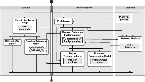
In the case study in Chapter 3 we saw the advantages that are gained from the separation of domain-related application development and technical infrastructure. We are able to formalize and generatively support the software architecture completely independent of the concrete application. In our example, we obviously dealt with the architecture-centric case: the domain was software infrastructure for e-business applications. A domain architecture with a correspondingly architecture-centric DSL (UML profile), a corresponding platform (J2EE and Struts), and suitable generator templates was developed. If we now generalize the principle, we get Figure 13.1.
Figure 13.1 Domain-related analysis and domain architecture as a basis for formal modeling.

One of the most important basic ideas behind MDSD is that the formal modeling step implies two prerequisites that are not without reciprocity, but which can for the most part be developed in parallel:
- The functional/professional requirements for an iteration or an increment of the concrete application must be known.
- The formal language to be used for modeling (the DSL) must be defined. In addition, for automatic further processing, the language must be bound to the concrete MDSD platform in the shape of transformation rules. This is what the term domain architecture sums up (Chapter 4).
As its name indicates, the domain architecture formalizes and supports a domain. In principle, this domain is independent of a single application (unique product), or in other words, it covers a software system family.
The activity diagram in Figure 13.1 should not be misunderstood as a waterfall process. It primarily shows the basic principle on which each iteration is based.
Formal modeling serves to connect the concrete application’s concepts with the concepts provided by the domain architecture – more precisely, the functionality is expressed in the language (DSL) provided by the domain architecture. The formal model is then transformed with the generator’s support and mapped to the platform. We have already seen how this can look in an architecture-centric case, and an example from the embedded systems domain is given in Chapter 16. In the case of the insurance domain, the DSL could contain constructs relevant for the insurance domain, for example by supporting effective modeling of insurance products. In consequence, the platform would consist of prefabricated domain-specific components such as tariff calculator or contract data entry, and the transformations would for example generate configurations for the domain-specific components from the insurance product model, which would then be evaluated at runtime. An insurance application could thus be created 100% automatically from the model. In contrast to the architecture-centric case, this use case does not require any manual coding.
The basic principle introduced above suggests that one should also apply the separation between application and domain architecture development for the process and organizational level, as well to maximize the positive effects. Accordingly, we suggest a separation of the (domain) architecture development thread and the application development thread.
13.2.2 Domain Architecture Development Thread
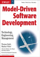
There are several artifacts and activities that are necessary or helpful for the creation of a domain architecture. The MDSD architecture development thread aims at reusability as well as at quality and efficiency enhancement. From a process perspective, it is the central aspect of MDSD. Figure 13.2 therefore first zooms in on the creation of a domain architecture activity, as discussed in the previous section.
Figure 13.2 Creation of a domain architecture.
The partitions displayed in the diagram divide the activities into the categories domain, transformation, and platform. In each category, artifacts of the domain architecture are produced (shown in light gray). Only the normal case scenario with the most important dependencies is shown here, because – in our experience – including everything else would obscure the essential issues. In particular, no iteration cycles are shown.
At the beginning of a project, a complete iteration though the stages shown in Figure 13.2 can take several weeks, compared to a couple of hours or even minutes in the course of the project, depending on the scope of the extensions or modifications. Parts of the domain architecture might already be present at project start-up, or a derivative of an existing domain architecture might be created.
At the beginning of a project we recommend an elaboration phase in which the architecture development thread is initially run completely, as a kind of bootstrapping activity for the project. This can be omitted if the project is conducted on familiar territory, for example if it is part of an existing software system family.
The following sections list the most important steps (actions/activities) and result types in detail.
Prototyping
A platform that is supposed to be used often already exists at the beginning of a project, such as J2EE or specific frameworks. One goal of the MDSD architecture development thread is to merge these artifacts with a semantically-rich and domain-specific MDSD platform (Section 7.6). To this end, it always makes sense first to gather experience with a prototype as a proof of concept. Among other things, this prototype can also be considered a first step towards the MDSD platform.
Developing the Platform
We defined the term MDSD platform in Chapter 4 and explained its constructive aspects in Chapter 7. The term runtime system is used synonymously. Runtime system components are ideal candidates for re-use, even across the boundaries of software system families.
As we have seen, the platform constitutes the foundation on which to base generated and non-generated code, and for keeping transformations simple. The generative portion of the domain architecture has a dependency on the runtime system components (platform) used, but the opposite is not true.
Development of the platform should also progress iteratively. Refactoring techniques (see [Fow99]) can be applied beneficially in this context.
It should also be observed that the border between platform and generated code can change in the course of the domain architecture’s evolution, in either direction. Chapter 7 elaborated the criteria for this.
Creating a Reference Implementation
The reference implementation is merely an intermediate result of the MDSD architecture development thread, but a very important one when it comes to the creation of a domain architecture.
The reference implementation should not be misinterpreted as a simple, isolated example from which one can derive suggestions for implementation if necessary. It can be created from a prototype, but serves a more significant purpose: together with the reference model/design, it demonstrates the application and realization of the DSL belonging to the domain. This two-part reference exemplifies the transition from model to implementation on the respective platform. For a new software system family, the reference implementation is first created manually. Later, the transformations are derived from it. The generative implementation of the reference model, possibly plus the manually programmed domain logic, must then result in a complete, executable reference implementation.
The full added value of a reference implementation will only be obtained from the interplay between the reference implementation and a reference model (and thus a DSL – see below). The concrete functional content of a reference implementation per se is irrelevant – only the domain matters. Yet as a rule a more or less sensible use case is implemented, if only in a minimalistic form. Sufficient coverage of the DSL’s constructs and their combinations is much more important. At the same time, the reference implementation demonstrates the use of the MDSD platform and its API.
For a new software system family, the reference implementation is first created completely by hand, but as soon as automatic transformations are available, the reference implementation is reduced to manually-programmed domain logic, if it exists. The rest of the application can then be generated from the reference model.
If you already have a number of applications in a specific domain and want to switch to a model-driven development process, the domain architecture can also be extracted from the existing applications, as long as the implementations are well-structured. This is often not the case with typical legacy applications, however.
It is also important to note that the domain architecture’s evolution, and particularly the early stage of bootstrapping (such as DSL definition and stabilization), will usually have repercussions for the reference implementation, and maybe also for the platform. This is completely normal in the context of iterative-incremental software development: a strict waterfall model would most likely be counterproductive here.
Domain Analysis/Design
This activity primarily serves to find the domain’s metamodel and a suitable, concrete DSL. Here we only list the best practices for constructing a DSL.
An architecture-centric DSL is also called a design language. The use of UML as its basis is typical (but not mandatory) for such a design language, as the case study in Chapter 3 shows in depth. UML is completely unusable for some aspects, however, such as for example the modeling of a GUI layout, so that one may have to use another notation. Ultimately the concrete syntax always assumes a less important role than the abstract syntax (see Chapter 4 and Section 11.2.2).
The following rules should be observed when designing any DSL:
- The DSL should be as abstract and as free of any technical terms that constitute an implementation detail of the MDSD platform as possible. This measure leads to models whose technical realization will only be recognized in the context of a platform binding. This simplifies subsequent migration or other architectural changes. Such DSLs are also reusable for various software system families. We have sometimes intuitively labeled such models platform-independent (PIM), but this expression is relative (see Chapter 4): typically, models are independent of an industry standard platform such as J2EE, but dependent on the concepts of the MDSD platform of the domain architecture, because the DSL precisely serves the purpose of enabling the use of these concepts on the model level.
- If possible, the DSL should cover all relevant concepts of the domain with language elements. Ideally, all schematically-implementable code fragments of the reference implementation should be covered by constructs of the DSL. Our case study exemplifies this: The stereotypes «Entity», «ProcessObject», «Presentation», «SystemUseCase», «Activity Controller», «ControllerState» and so on name and cover precisely the architectural concepts of our example domain architecture.
- The DSL should be as compact as possible and not have any redundancy. It can also possess dynamic constructs, for example to render business processes and controller logic in the shape of activity or state diagrams.
- The DSL must make the well-formedness of models verifiable. It must be guaranteed that all modeling notations offered by the base language are excluded, in case they are not legal for the DSL, especially if the DSL is a specialization of a more general language, such as a UML profile as a specialization of the UML.
With the conception of the DSL, the architect inevitably also draws the dividing line between generated code and domain logic – and thus the degree of freedom of the developers. One extreme is the attempt to expand the DSL to such an extent that manual programming is no longer needed (see Chapters 4 and 7). These days, this approach – if applied in the extreme – is neither practicable nor useful for typical business applications in the context of architecture-centric development.
The pivotal question here is which implementation aspects should be covered by an architecture-centric DSL and which should not. The following questions can serve as a guideline:
- Does the reference implementation feature code fragments with copy-paste characteristics that have not been generated yet?
- Would modeling of these aspects be simple and compact, or would it in contrast require even more effort and be more comprehensive than manual coding?
This important assessment requires some experience and sensitivity toward the subject matter.
The DSL must be documented in order to be usable. This includes the following aspects:
- The concrete syntax, for example a UML profile or an XML schema.
- The abstract syntax, for example as a MOF diagram – see Chapter 6.
- The static semantics — that is, constraints or modeling rules: which constructs are not allowed, which are mandatory. In the case of a UML-based modeling language, this is a part of the profile (see Chapter 3).
- The semantics — the meaning of the language constructs in textual form. The semantics are formally defined by the reference implementation and the transformation rules, so their definition is geared to a concrete platform. To avoid this, and to increase its reusability, the semantics should be described in as general a form as possible, using the architectural concepts rather than the platform itself.
- An example model, for example, the reference design (see the next section)
The definition of an adequate modeling language is certainly one of the greatest challenges in MDSD. Section 13.5 offers a couple of concrete tips. Some practical experience, or an existing basis such as the UML profile from this book’s first case study, are required. From that point on the modeling language can undergo evolutionary development. For example, it is typical for it to take a while before one notices that the original design of specific modeling constructs is not sufficiently abstract and needs to be generalized. Refactoring is therefore a strong ally at this metalevel. Admittedly, fundamental changes in the abstract syntax – of the actual language structure – and the semantics can bring about extensive changes of existing transformation rules. In contrast, language extensions are uncritical. During the elaboration phase an adequate emphasis should be put on the DSL, so that the transformation rules are only derived when reference implementation and reference design are coherent.
As a rule, modeling languages are not created in a vacuum. To get a feel for whether the chosen constructs are adequate and ergonomic, you have to use the language in practice. This purpose is being served by the reference design.
Creating the Reference Model/Design
The reference model is an instance of the DSL, in that it expresses a domain example via the means of the DSL.
The interplay with the reference implementation is important: the reference model and the reference implementation together exemplify the syntax and semantics of the DSL, and thus make concrete the concept of the domain architecture in detail.
Documenting the Programming Model
The definition of a programming model is only relevant if the domain architecture contains ‘semantic gaps’, meaning that a code framework emerges via the model transformation that must be supplemented by the application developer in a programming language to enable the creation of a runnable application.
We established the term programming model in Chapter 7. CORBA, for example, defines an abstract interface definition language (IDL) with mappings to various programming languages such as C++ and Java. The programming model of the respective language mapping then defines naming conventions for the mapping of IDL constructs to language constructs such as classes, attributes, and methods. These conventions are obeyed by the IDL compiler (generator), which generates the respective signatures and skeletons. Generation from the IDL definition creates a well-defined API that allows application developers to program the application logic. The programming model defines specific idioms and patterns that describe how to treat the respective architecture correctly – not all rules can be automatically checked by the compiler or the runtime system.
In the context of MDSD, the programming model describes the application developer’s view of the domain architecture. The goal is among others to make it transparent to the developer which programming language-related artifacts are created from the DSL’s constructs that are relevant to them. An association in the model, for example, can mean a set of access operations, such as getElementAt(), addElement(), removeElement() and so on, on the implementation level. From the developer’s viewpoint, the implementation is irrelevant: they only needs the signatures. These will then constitute the programming model of the DSL association construct.
The programming model is quite easily to document in table form. The table contains – besides the respective construct of the DSL – a reference to an adequate excerpt of the reference model and the reference implementation. Opinions over the need for explicit documentation of the programming model vary, but the deliberate definition in the form of MDSD transformation and platform API is necessary. The reference implementation constitutes an implicit documentation. However, if the programming model contains ‘do’s’ and ‘don’ts’ that cannot be enforced or controlled via tools, explicit documentation is mandatory.
It turns out that a tutorial in the form of a walkthrough that explains to developers how to develop concrete applications using the DSL is most appropriate. Such a tutorial should cover the DSL as well as other aspects of the programming model, including the code that needs to be written manually, or how to operate/integrate the generator tool.
The initial programming model and its documentation are typically constructed in the course of the elaboration phase. The programming model is also subject to iterative improvements, of course.
Deriving Transformations
This activity formalizes the mapping of a DSL to a platform and programming model, to the extent that an automatic transformation can transform a given application model into an implementation or a skeleton.
In our case study a set of generator templates was created in this step. The templates were derived from the reference implementation with the help of the reference model. The generator framework used in the case study in Chapter 3 relocates part of the metaprogramming to the creation of a DSL’s metamodel, implemented in Java. From the process viewpoint, this separation is merely an implementation detail and thus irrelevant.
If the domain logic of an application cannot entirely be expressed by the DSL, techniques for the integration of generated and non-generated code are needed (see Chapter 7).
Creating a DSL Editor
Not all DSLs are UML profiles, so that a standard tool can be applied, with varying degrees of effectiveness. In the case of highly-specialized domains it is common practice and advisable to create a specific tool for defining DSL-conforming models, for example to further increase the ergonomics and therefore the efficiency of the MDSD approach. It comes down to a question of the cost-value ratio, which can only be answered for each individual case. This topic is considered further in Section 13.5.
13.2.3 Application Development Thread
This section deals with the viewpoint of the application developer’s who works with a given domain architecture (see Figure 13.3).
Figure 13.3 Activities in the application development thread.
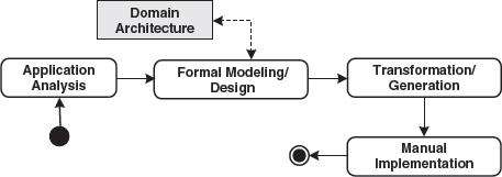
Here too the simple, normal case without iteration cycles is shown. One cycle can take anything from a couple of days to only minutes, depending on the intensity of the single steps.
Formal Modeling/Design
The analysis and architectural threads meet in this step: the functional requirements are now expressed in the domain architecture’s language – the DSL. The reference model serves as an orientation guide in this context. This step constitutes a real gain of information and insight and therefore cannot be automated.
A working feedback loop to the architecture development thread should be established here, because deficiencies or errors in the DSL are regularly discovered, especially in the early stages of a domain architecture. It is also typical that the potential for further automation to be discovered during application development, which leads to extension or even generalization of the DSL.
Generation
This step can be executed purely mechanically. No information gain occurs when compared to the formal model: it is transformed automatically into a form suitable for the MDSD platform via the domain architecture’s transformations. During this process integration points for manually-programmed domain logic can emerge in defined locations. These can be protected regions, whose content remains intact during iterative regeneration, or implementation classes to which the implementation framework delegates (Section 8.2.6).
Manual Implementation
Domain logic that cannot be expressed in the DSL must be added manually after generation has taken place. In our case study, these are exactly the contents of the protected regions in the implementation skeleton.
Repercussions for the domain architecture can occur even during implementation. The project’s organization must allow for the necessary feedback loops.
Organizational Aspects
The separation between application development and domain architecture development should ideally be supported not only by a suitable process structure, but also by adapting the organizational structure of a team, project, or company. These are treated in Chapters 19 and 15.
13.3 Two-Track Iterative Development
We have now discussed the separation of roles and artifacts between application development and domain architecture development. This section is about the synchronization of both threads. There is obviously a dependency from application development to domain architecture development – in the same way that you might depend on the development of a framework that you use. From a requirements management viewpoint, this means that the application development team assumes the customer’s role for domain architecture development.
When developing the domain architecture, you should simultaneously also develop at least one application based on that domain architecture as if it were a separate project. In practice, this means that in one iteration the application developers always use the domain architecture developed in the last iteration, so that they are always one iteration ahead of the application developers. Make sure that the application developers always provide feedback to the domain architecture developers.
New versions of the domain architecture are always integrated at the beginning of an iteration. To reach a sufficient level of agility during the development process, iterations should not take longer than a maximum of four to six weeks. Ideally and to simplify matters, we recommend that a fixed timeframe is set for all iterations (timeboxing). This leads to a regular development rhythm that the teams will get used to.
Figure 13.4 Iterative two-track development.

Note that the incremental, iterative process based on synchronized timeboxes does not exclude a domain analysis prior to entering the iterative cycle. On the contrary, a good understanding of the basic concepts of the domain is actually needed. As soon as application development is under way, further domain analysis takes place iteratively – as part of the architecture development thread that is now delegated to a project of its own.
Infrastructure teams (the domain architecture developers) sometimes show a tendency to jump at interesting technologies to impress the world – of course with the best intentions – with some new ‘silver bullet’. This risk is alleviated most efficiently by the formation of an architecture group that consists of representatives from the application development team (see Chapter 19). Such a group is entitled to determine the functionality and features of infrastructure development via scope trading from iteration to iteration, and decides over the acceptance of infrastructure functionality via the validation of (domain architecture) iterations. This guarantees that the developed domain architecture constitutes real added value for application development and actually supports application developers in their everyday work.
Timeboxing with a fixed budget, scope trading, and validation of iterations are agile techniques that support iterative requirements management and can be particularly helpful in combination with two-track, iterative development for MDSD. Here, we only want to sum up the basic ideas in a few sentences, because these topics are in principle independent of MDSD.
A fixed budget is available for each timebox. At the beginning of each iteration, the features and priorities for the iteration are negotiated with stakeholders, for example customers and end users, in a scope-trading workshop. For reasons of risk minimization, architectural aspects must be considered as well. The timebox budget must not be exceeded. Within the timebox, the feature set remains constant, so that developers can pursue their goal of delivering software that can be validated at the end of the timebox. The validation at the end of an iteration conducted by the stakeholders decides which features meet the requirements and which features must be reengineered. New requirements that have been recognized in the meantime are reprioritized on an equal footing with unfulfilled requirements.
Further sources dealing with these topics can be found on the Web at http://www.mdsd.info.
In the context of MDSD these practices can be especially helpful for establishing a working feedback loop between application development and domain architecture development. In this context the application developers serve as a representative team of scope trading stakeholders in domain architecture development.
13.4 Target Architecture Development Process
Best practices for the domain architecture development process are one thing. Other important concerns are:
- How do you come up with a reasonable target architecture?
- How do you make it ‘ready for MDSD’?
- How do you implement it in non-trivial projects?
The following sections provide some help in this area: they deal with process best practices, with a focus on the target architecture – which of course is reflected by the domain architecture at the metalevel too. In other words, it’s a relevant perspective for all activities in the architecture development thread introduced above. Many of the following statements and suggestions concerning target architecture development are independent of MDSD, but some of them are MDSD-aware, as we will see.
Software architecture is generally too technology-driven. You hear statements such as “We have a Web Service architecture”. This statement is not very informative, because it describes only one aspect of the overall system (its communication), and because Web Services are a particular implementation technology for that aspect. There is much more to say about the architecture, even about its communication aspects, than just a realization technology. The same is true of ‘EJB architectures’ or a ‘thin-client architecture’. Too early a commitment to a specific technology usually results in blindness to the concepts and too tight a binding to the particular technology. The latter in turn results in a complicated programming model, bad testability, and no flexibility to change the technology as QoS requirements evolve. It obscures really important issues.
Another problem is the ‘hype factor’. While it is good practice to characterize an architecture as implementing a certain architectural style or pattern [POSA1], some of the buzzwords used today are not even clearly defined. A ‘service-based architecture’ is a classic. Nobody knows what this really is, and how it is different from well-designed component-based systems. There are many such misunderstandings. People say ‘SOA’, and others understand ‘Web Service’! Also, since technologies are often hyped, a hype-based architecture often leads to too early – and wrong – technology decisions.
Another problem is what we usually call industry standards. A long time ago, the process of coming up with a standard was basically as follows: try a couple of alternatives, see which one is best, set up a committee that defines the standard based on previous experiences. The standard is therefore usually close to the solution that worked best. Today this is different. Standards are often defined by a group of (future) vendors. Either they already have tools, and the standard must accommodate all the solutions of all the tools of all the vendors in the group, or, there is no practical previous experience and the standard is defined from scratch. As a consequence of this approach, standards are often unusable because there was no previous experience, or overly complicated (because it must satisfy all the vendors). Thus, if you use standards for too many aspects of your system, your system will be complicated!
Finally, there’s politics.
All these factors, taken together, prevent people from thinking about the really relevant aspects of an architecture. In our opinion these include architectural patterns, logical structures (architectural metamodels), programming models for developers, testability, and the ability to realize key QoS concerns.
The following sections sketch what we consider a reasonable approach to software architecture – that is, MDSD-target-architecture. It also paves the way for automation of many aspects of software development, a key ingredient to MDSD and product-line engineering.
We are not the only ones seeing this problem in current software architecture, of course. There are good architectural resources that you should definitely read, such as [POSA1], [POSA2], and [POSA3], as well as [JB00], [VSW02] and [VKZ04].
13.4.1 Three Phases
The development of a software architecture, especially one that can be used in the context of MDSD, should be executed in three phases. In each of these phases certain core artifacts are created – these are highlighted in smallcaps in the following:
- Elaboration. In the first phase, the elaboration, you define a technology-independent architecture. Based on it, you define a workable programming model for the developers that work with the architecture. To let developers run their applications locally, a mock platform is essential. Finally in this phase, you define one or more technology mappings that project the technology-independent architecture on a particular platform that provides the required/desired QoS features. A vertical prototype verifies that the system performs as desired – here is where you run the first load tests and optimize for performance – and that developers can work efficiently with the programming model.
- Iteration. The second phase iterates over the steps in the first phase. While we generally recommend an agile approach, we emphasize the fact that you typically don’t get it right first time. You usually have to perform some of the steps several times, especially the technology mapping and the resulting vertical prototype. It is important that you do this before you dive into Phase 3, automation.
- Automation. The third phase aims at automating some of the steps defined in the first phase and refined in the second phase, making the architecture useful for larger projects and teams. First, you will typically want to generate glue code to automate the technology mapping. Also, you might often notice that even the programming model involves some tedious repetitive implementation steps that could be expressed more briefly with a dslbased programming model. Finally, model-based architecture verification helps to ensure that the architecture is used correctly even in large teams.
In the following sections we outline each of these steps, while an example of this approach is given in the case study in Chapter 17.
13.4.2 Phase 1: Elaborate
The best practices of this phase are relevant for the activities of prototyping, document programming model and platform development of our domain architecture development thread.
Technology-Independent Architecture
How do you define a software architecture that is well-defined, long-lived and feasible for use in practice? The architecture has to be reasonably simple and explainable on a beer mat. You want to make sure that the architectural concepts can be communicated to stakeholders and developers. Implementation of functional requirements should be as efficient as possible. The architecture must survive a long time, longer than typical hype or technology cycles. The architecture might also have to evolve with respect to QoS levels such as performance, resource consumption, or scalability.
To achieve these goals, define the architectural concepts independently of specific technologies and implementation strategies. Clearly define concepts, constraints, and relationships of the architectural building blocks – a glossary or an architectural metamodel can help here. Define a technology mapping in a later phase to map the artifacts defined here to a particular implementation platform. Use well-known architectural styles and patterns here. Typically these are best practices for architecting certain kinds of systems independently of a particular technology. They provide a reasonable starting point for defining (aspects of) your system’s architecture.
If you use less complicated technology, you can focus more on the structure, responsibilities, and collaborations among the parts of your systems. Implementation of functionality becomes more efficient, and you don’t have to educate all developers with all the details of the various technologies that you’ll eventually use.
However, the interesting question is: how much technology is in a technology-independent architecture? For example, is AOP1 ok? In our opinion, all technologies or approaches that provide additional expressive concepts are useful in a technology-independent architecture. AOP is such a candidate. The notion of components is also one such concept. Message queues, pipes and filters, and, in general, architectural patterns are also useful.
When documenting and communicating your technology-independent architecture models are useful. We are not talking about formal models as they’re used in MDSD – we’ll take a look at these later. Simple box and line diagrams, layer diagrams, sequence, state or activity charts can help to describe what the architecture is about. They are used for illustrative purposes, to help reason about the system, or to communicate the architecture. For this very reason, they are often drawn on beer mats, flip charts, or with the help of Visio or PowerPoint. While these are not formal, you should still make sure that you define what a particular visual element means intuitively – boxes and lines with no defined meaning are not very useful, even for informal diagrams.
Programming Model
Once you have defined a technology-independent architecture and your architecture is rolled out, developers have to implement functionality against it. The architecture is a consequence of many non-functional requirements and the basic functional application structure, which might make the architecture non-trivial and hard to comprehend for developers. How can you make the architecture accessible to (large numbers of) developers?
To make sure that it’s benefits can actually materialize, you want to make sure the architecture is used correctly. You have developers of differing qualifications in the project team. All of them have to work with the architecture. You want to be able to review application code easily and effectively. Your applications must remain testable.
To achieve all this, define a simple and consistent programming model. A programming model describes how an architecture is used from a developer’s perspective. It is the ‘architecture API’. The programming model must be optimized for typical tasks, but allow for more advanced applications if necessary. Note that a ‘how to’ guide that walks developers through the process of building an application is a main constituent of a programming model.
The most important guideline when defining a programming model is usability and understandability for the developer. This is the reason why the documentation for the programming model should always be in the form of tutorials or walkthroughs, not as a reference manual! Frameworks, libraries, and – as we’ll see in dsl-based programming model on page 270 – domain-specific languages are useful here.
Sometimes it is not possible to define a programming model completely independently of the platform on which it will run (see the next section, technology mapping). Sometimes the platform has consequences for the programming model. For example, if you want to be able to deploy something as an Enterprise Bean, you should not create objects yourself, since this will be done later by the application server. There are a couple of simple guidelines that can help you to come up with a programming model that stands a good chance of being mapped to various execution platforms:
- Always develop against interfaces, not implementations
- Never create objects yourself, always use factories
- Use factories to access resources (such as database connections)
- Stateless design is a good idea in enterprise systems
- Separate concerns: make sure a particular artifact does one thing, not five.
A good way to learn more about good programming models and technology-independent architecture can be found in Eric Evans wonderful book on domain-driven design [Eva03].
One of the reasons why a technology decision is made early in the project is political pressure to use a specific technology. For example, your customer’s company might already have a global lifetime license for IBM’s Websphere and DB2: you therefore have no option but to use those. You might wonder whether the approach based on a technology-independent architecture and explicit technology mappings can still work. If the imposed technology is a good choice, the benefits of the approach described here still apply. If the technology is not suitable (because it is overly complicated or unnecessarily powerful), life with the technology will be easier if you isolate it in the technology mapping.
Technology Mapping
Your software has to deliver certain quality of service (QoS) levels. Implementing QoS as part of the project is costly. You might not even have the appropriate skills in the team. Also, your system might have to run with different levels of QoS, depending on the deployment scenario. You don’t want to implement the advanced features that enable all the non-functional requirements yourself. You want to keep the conceptual discussions, as well as the programming model, free from such technical issues.
Therefore, map the technology-independent architecture to a specific platform that provides the required QoS. Make the mapping to the technology explicit. Define rules about how the conceptual structure of your system (the metamodel) can be mapped to the technology at hand. Define those rules clearly to make them amenable for glue code generation.
Decide about standards usage here, not before. As mentioned, standards can be a problem, but they can also be a huge benefit. For issues that are not related to your core business, using standards is often useful. But keep in mind: first solve the problem, then look for a standard, not the other way around. Make sure programming model hides the complexity too.
Use technology-specific design patterns here. Once you decided on a specific platform, you have to make sure you use it correctly. A platform is often not easy to use. If it is a commonly-used platform, though, platform-specific best practices and patterns should be documented. Now is the time to look at these and use them as the basis for the technology mapping.
Let’s recap: the technology-independent architecture defines the concepts that are available to build systems. The programming model defines how these concepts are used from a developer’s perspective. The technology mapping defines rules about how the programming model artifacts are mapped to a particular technology.
The question is now, which technology should you chose? In general this is determined by the QoS requirements you have to fulfill. Platforms are good at handling technical concerns such as transactions, distribution, threading, load-balancing, failover, or persistence – you don’t want to have to implement these yourself. So always use the platform that provides the services you need, in the QoS level you are required to deliver. Often this is deployment-specific.
Sometimes you have to decide on your platform based on politics, of course. If a company builds everything on Oracle and Websphere, you’ll have a hard time arguing against these. However, the process based on this and the two aforementioned best practices, technology-independent architecture and programming model, IS still useful, because it allows you to understand the consequences of not using the ideal platform. You might have to use a compromise, but at least you will know that it is one!
Mock Platform
Based on the programming model, developers now know how to build applications. In addition to that, developers have to be able to run (parts of) the system locally, at least to run unit tests. How can you ensure that developers can run ‘their stuff’ locally without caring about the technology mapping and its potentially non-trivial consequences for debugging and test setup? You also want to ensure that developers can run their code as early as possible. You want to minimize dependencies of a particular developer on other project members, specifically those caring about non-functional requirements and the technology mapping. You have to make sure developers can efficiently run unit tests.
Define the simplest technology mapping that could possibly work. Provide a framework that mocks or stubs the architecture as far as possible. Make sure that developers can test their application code without caring about QoS and technical infrastructure.
This mock platform is essential in larger and potentially distributed teams to allow developers to run their own code without caring too much about other people or infrastructure. This is essential for unit testing! Testing one’s business logic is simple if your system is well modularized. If you stick to the guidelines given in the programming model (interfaces, factories, separation of concerns) it is easy to mock technical infrastructure and other artifacts developed by other people.
Note that it’s essential that you have a clearly-defined programming model, otherwise your technology mapping will not work reliably. Also, the tests you run on the mock platform will not find QoS problems – QoS is provided by the execution platform.
Vertical Prototype
Many of the non-functional requirements your architecture has to realize depend on the technology platform, which you selected only recently in the technology mapping. This aspect cannot be verified using the mock platform, since it ignores most of these aspects. The mapping mechanism might even be inefficient. How do you make sure you don’t run into dead-ends? You want to keep your architecture as free of technology-specific concerns as possible. However, you want to be sure that you can address all the non-functional requirements. You want to make sure you don’t invest into unworkable technology mappings.
Thus, as soon as you have a reasonable understanding of the technology-independent architecture and the technology mapping, make sure you test the non-functional requirements. Build a vertical prototype: an application that uses all of the above and implements it only for a very small subset of the functional requirements. This specifically includes performance and load tests.
Vertical prototypes are a well-known approach to risk reduction. In the approach to architecture suggested here, the vertical prototype is even more critical than in other approaches, since you have to verify that the programming model does not result in problems with regard to QoS later. You have to make sure the various aspects you define in your architecture really work together.
13.4.3 Phase 2: Iterate
Now that you have the basic mechanisms in place, you should ensure that they actually work for your project. Therefore, iterate over the steps given above until they are reasonable stable and useful.
Then, roll out the architecture to the overall team if you have larger project teams. If you want to start a model-driven development process, continue with Phase 3.
13.4.4 Phase 3: Automate
The best practices of this phase are relevant for the activities derive reference implementation/model, derive transformations and domain analysis/design of the domain architecture development thread.
You have a technology-independent architecture. You want to automate various tasks of the software development process. To be able to automate, you have to codify the rules of the technology mapping and define a dsl-based programming model. For both aspects, you have to be very clear and precise about the artifacts defined in your technology-independent architecture. Automation cannot happen if you can’t formalize translation rules. An architectural definition based on prose is not formal enough: you want to be able to check models for architectural consistency.
Therefore, define a formal architectural metamodel. An architectural metamodel formally defines the concepts of the technology-independent architecture. Ideally this metamodel is also useful in the transformers/generators that are used to automate development.
Formalization is a double-edged sword. While it has some obvious benefits, it also requires a lot more work than informal models. The only way to justify the extra effort is by gaining additional benefits. The most useful benefit is for the metamodel not to just collect dust in a drawer, but really to be used by tools in the development process. It is therefore essential that the metamodel is used, for example as part of the code generation in dsl-based programming models and architecture-based model verification.
Glue Code Generation
The technology mapping – if sufficiently stable – is typically repetitive and thus tedious and error-prone to implement. Also, often information that is already defined in the artifacts of the programming model have to be repeated in the technology mapping code (method signatures are typical examples). A repetitive, standardized technology mapping is good, since it is a sign of a well-though-out architecture. Repetitive implementations always tend to lead to errors and frustration.
To take care of these issues, use code generation based on the specifications of the technology mapping to generate a glue code layer, and other adaptation artifacts such as descriptors, configuration files, and so on. To make that feasible you might have to formalize your technology-independent architecture into an architectural metamodel. To be able to get access to the necessary information for code generation, you might have to use a dsl-based programming model.
Build and test automation is an established best practice in current software development. The natural next step is to automate programming – at least those issues that are repetitive and governed by clearly-defined rules. The code and configuration files that are necessary for the technology mapping are a classic candidate. Generating these artifacts has several advantages. First of all, it’s simply more efficient. Second, the requirement to ‘implement’ the technology mapping in the form of a generator helps to refine the technology mapping rules. Code quality will typically improve, since a code generator doesn’t make any accidental errors – it may well be wrong, but then the generated code is typically always wrong, making errors easier to find. Finally, developers are relieved from having to implement tedious glue code over and over again, a boring, frustrating, and thus error-prone task.
DSL-based Programming Model
You have defined a programming model. However, your programming model is still too complicated, with a lot of domain-specific algorithms implemented over and over again. It is hard for your domain experts to use the programming model in their everyday work. The glue code generation needs information about the program structure that is hard or impossible to derive from the code written as part of the programming model. The programming model is still on the abstraction level of a programming language. Domain-specific language features cannot be realized. Parsing code to gain information about what kind of glue code to generate is tedious, and the code also does not have the necessary semantic richness.
Define domain-specific languages that developers use to describe application structure and behavior in a brief and concise manner. Generate the lower-level implementation code from these models. Generate a skeleton against which developers can code those aspects that cannot be completely generated from the models.
A DSL-based programming model marks the entrance into the Model-Driven Software Development arena. Defining DSLs for various aspects of a system and then generating the implementation code – fitting into the programming model defined above – is a very powerful approach. On the other hand, defining useful DSLs, providing a suitable editor, and implementing a generator that creates efficient code is a non-trivial task. So this step only makes sense if the generator is reused often, and the ‘normal’ programming model is so intricate, that a DSL boosts productivity, or if you want to do complex model-based architecture validation.
The deeper your understanding of the domain becomes, the more expressive your DSL can become (and the more powerful your generators need to be). To manage the complexity you should build cascades of DSL/generator pairs. The lowest layer is basically the glue code generator: higher layers provide more and more powerful dsl-based programming models.
Model-based Architecture Validation
You now have all the artifact in place and you roll out your architecture to a larger number of developers. You have to make sure that the programming model is used as intended. Different people might have different qualifications. Using the programming model correctly is also crucial for the architecture to deliver its QoS promises. Checking a system for architectural compliance is critical. However, using only manual reviews for this activity does not scale to large and potentially distributed teams. Since a lot technical complexity is taken away from developers (it is in the generated glue code) these issues need not be checked. Checking the use of the programming model on the source-code level is complicated, mostly as a consequence of the intricate details of the programming language used.
Make sure critical architectural issues are either specified as part of the dsl-based programming model, or the developers are restricted in what they can do by the generated skeleton into which they add their 3GL code. Architectural verifications can then be done at the model level, which is quite simple: it can be specified against the constraints defined in the architecture metamodel.
This is where you want to arrive. In larger projects you have to be able to verify the properties of your system, from an architectural point of view, via automated checks. Some of them can be done at the code level, by using metrics and so on. However, if the system’s critical aspects are described in models, you have much more powerful verification and validation tools at hand.
It is essential that you can use the architecture metamodel to verify models/specifications. Good tools for Model-Driven Software Development such as the openArchitectureWare generator [OAW] can read (architecture) metamodels and use them to validate input models. In this way a metamodel is not ‘just documentation’, it is an artifact used by development tools.
13.5 Product-Line Engineering
Product-line engineering (PLE) deals with the systematic analysis of domains and covers the design of software production lines. Its goal is to fully leverage the potential for automation and reuse during the development of software systems. Product-line engineering thus seamlessly integrates into the MDSD context as a method for analysis.
In other words, it provides a solid background for all activities in the domain part of the domain architecture development thread, as introduced in Figure 13.2.
A comprehensive discussion of PLE would exceed the scope of this book, so we content ourselves with introducing the basic principles and explaining how they tie into MDSD. At the end of this chapter a comprehensive list of further reading is provided. We address the economic and organizational aspects of product-line engineering in Part 4 of this book.
13.5.1 Software System Families and Product Lines
Two key terms, software system family and product line, were briefly defined in Chapter 4.
The original definition of a software system family is as follows:
We consider a set of programs to constitute a family whenever it is worthwhile to study programs from the set by first studying the common properties of the set and then determining the special properties of the individual family members. [Par76]
We are faced with a software system family whenever a series of systems is developed – in this context, often referred to as products – that have relevant properties in common. In the context of MDSD, these properties are consolidated in the domain architecture. This implies these commonalities can be of an infrastructural, architectural, or functional/professional nature, depending on the nature of the domain.
A product line, on the other hand, consists of a set of functionally-related products with a common target market: its organization is customer group-specific. Ideally, a product line is realized with the help of a software system family.
13.5.2 Integration into the MDSD Process
Let’s look at the development process described above. Analytical activities emerge in various places. These are:
- The definition and boundaries of the domain for which software is to be developed.
- The definition of the most important core concepts of the domain.
- Analysis of the commonalities and differences between software systems of the domain – and thus…
- The separation between application and domain architecture.
- The definition of the most important basic components of the MDSD platform (its solution space).
- The definition of the production process for the software system family.
Product-line engineering provides a methodical basis for systematic reuse in the context of software system families.
MDSD can either be considered an implementation technology for product-line engineering. Similarly, product-line engineering can be seen as an analysis method for MDSD. Product-line engineering practices can and should be used iteratively and incrementally: PLE should not be seen as a separate pre-stage of MDSD, but rather as an accompanying method, even though it is certainly prominent during early phases of an MDSD project.
13.5.3 Methodology
The product-line engineering process consists of three phases – see Figure 13.5. We explain these below.
Figure 13.5 The phases of product-line engineering.

Domain Analysis
The first step in domain analysis is domain scoping. Here, the boundaries of the domain are determined. If for example, we consider the domain of automotive engine controllers, it is important to define whether this domain includes only gasoline engines or is also suitable for diesel engines, and whether they are used only for personal vehicles or also for trucks. This is important for two reasons:
- Things that are so different that they cannot be reasonably mapped into the context of a family must be excluded to allow a consistent realization. This is a risk minimization strategy.
- Unclear requirements result in on-going discussions during the project. This does not mean that iterative requirements management is prohibited, but merely that the requirements (in this case the scope) should be clearly defined at any given time.
This also explains why it makes sense to use this approach primarily in mature domains: if you don’t yet know the differences between the domain products, you cannot make the necessary decisions2.
Let’s return to the first case study in Chapter 3. The domain there was ‘application architecture for e-business software’. The car-sharing application is a product of that domain. If you now start with architecture bootstrapping via a reference implementation, you will without doubt only succeed if the architects already have some knowledge about layering, typical J2EE patterns, MVC structures, declarative flow control, and so on. Since this is fairly common knowledge among developers, one can speak of a ‘mature’ domain here. However, it is not necessary to know the concrete implementation of the architecture’s patterns at the beginning of the project. The design language (UML profile) can to a certain extent evolve further in the course of the project (see Chapter 3).
There are various ways of learning about the differences between the discrete products of the family and documenting them systematically. One powerful method is derived from the FODA method [FODA] and goes under the name of feature modeling [EC00].
A feature model is graphically expressed by a feature diagram, and shows which features the constituent products of a software system family can or must have. A feature model is a hierarchical structure in which each feature can contain subfeatures. These can be mandatory for a specific product, optional, alternative, or n-of-m. Figure 13.6 clarifies these terms, showing a (simplified) feature diagram for the system family stack.
Figure 13.6 Example feature diagram.

The diagram describes the fact that each stack must have an element type: ‘must’ is expressed by the filled-in circle denoting a mandatory feature. This can be of the type int, float or string. This 1-of-n relationship, also called alternative, is recognizable by the open arc between the associations ElementType-int, ElementType-float and ElementType-string. The size of the stack can either be fixed (which means you have to assign a size) or be dynamically adaptable. The stack can optionally have a static counter, shown by an empty circle. If it doesn’t, the size is recalculated each time size() is invoked. Further features are thread safety, bounds checking, and type safety. One or more of these features can be contained in one product (an n-of-m relationship, shown by the filled arc). Moreover, the implementation can either be optimized for speed or memory consumption.
The diagram in Figure 13.6 therefore describes the ‘configuration space’ for members of the system family stack. Discrete members must be built from valid combinations of the features, for example:
- Dynamic size, ElementType: int, counter, thread-safe
- Static size with the value 20, ElementType: string
- Dynamic size, optimized for speed, bounds check
Apart from the specifications that are visible from the graphical notation, a feature model can contain even more information, such as names for specific combinations of features (macros), the multiplicity of subfeatures, the priority of a feature in the implementation, stakeholders affected by a feature, and so on. Additional constraints that cannot be expressed with the visual notation alone can also be defined. Practice shows that it is possible to go quite a long way in specifying the following additional constraints:
- Requires. A specific feature inevitably requires another.
- Excludes. The presence of one feature prohibits the simultaneous existence of another.
- Recommends. A milder variant of requires. A specific feature makes the use of another advisable.
- Discourages. A milder variant of excludes. One should not use two such features simultaneously.
As an example, here are the two optimization features:
- Optimization for speed: requires counter, requires fixed size, discourages thread safety, discourages bounds check.
- Optimization for memory usage: requires dynamic size, discourages counter.
What is interesting about this method and notation is that it says absolutely nothing about the subsequent implementation of the features. If a system family had already been modelled using UML in this phase, decisions would have to be made regarding inheritance, type genericity, associations, and so on this early in the development. However, this is neither necessary nor helpful during domain analysis. At this point, we are only interested in an analysis of the conceptual commonalities and differences between the products of a software system family. How these variabilities are implemented later is determined during the design phase.
The features shown in Figure 13.6 can even belong to two fundamentally different categories that are not distinguished by the feature model:
- Classic component features define the existence of modular features – that is, whether a product possesses a certain subsystem/module or not.
- In contrast, aspect features are those that cannot be realized as components, for example the features ‘optimized for performance’ or ‘optimized for code size’. Such features may later affect various points in the system and cause different components to be implemented in another way.
Feature diagrams can have both types of features side by side, whereas aspect features especially are very difficult to express with UML.
It is important in this phase to define dependencies between features. A product can maybe only have certain features when it also has certain other features as well. The opposite is also possible, of course – certain features exclude each other. This results in an ordered sequence of decisions that need to be made when building the product. This is essential for defining the production process in the next step. The definition of meaningful defaults in case specific features are not explicitly specified is of equal importance.
You can find further examples of feature models in the second case study, in Chapter 16.
Domain Design and Implementation
The definition of the software structure is one aspect of domain design. One starts by implementing the common features of a domain’s products in the form of a platform. Because these common features are identical for all products, it is not necessary to implement them generatively in any way: they constitute the basis of the common target architecture.
For the variable features – those in which the various products differ – one must decide when a feature must be bound – that is, the point at which one decides for or against a certain feature for a product. A variety of alternatives exists:
- At the source code level. Here, the decision for or against a feature is made during programming – that is, it is hard-wired into the source code.
- At compile time. Some decisions can be left to the compiler, such as overloaded functions, preprocessors, code/aspect weaver.
- At link time. The linker can be used to configure a product by binding one or another library, for example using a makefile that does or does not statically bind specific libraries.
- At installation time. For products that contain an explicit deployment step, one can typically still carry out specific configurations during deployment. For example, J2EE offers the option of adapting configurations during installation via deployment descriptors.
- At load time. You can also intervene while the application is loading. DLLs are one example of this, for example optional loading of different DLLs that implement the same functions in different ways.
- At runtime. Finally, you can also make decisions at runtime, for example polymorphism, dynamic class-loading in Java, interpreted configuration parameters.
All these options have their advantages and disadvantages:
- Performance. Typically the performance of features implemented directly in code is significantly better than decisions made dynamically at runtime. Decisions at compile time usually possess the same level of performance: decisions that are made by the linker or loader are in most cases not much slower.
- Code size. If behavior must be changeable at load time or runtime, the code for all alternatives must be present in the program image. The size of the image therefore grows. In this context we have to differentiate between the code size of the image and that of the running program. Decisions made by the compiler are usually quite close to the optimum. However, one must ensure that the compiler does not produce overhead through expansion (a potential risk when working with C++ templates, for example).
- Flexibility. Features that are hard-coded cannot be changed unless they are reprogrammed. Flexibility generally increases the later a decision for or against the feature is made – the later it is bound
- Complexity. Specific features can easily be removed or reintegrated into the system quite late, such as the dynamic loading of a component. Aspect-like features are more problematic, because they cut across the entire system, or large parts of it. The earlier they are defined, the easier they can be realized.
The production process describes how an executable product is created from a product specification (the model). MDSD offers one alternative for efficiently and consistently realizing the alternatives just listed.
A generator is the ideal tool for this purpose. At the source code level, this is obvious: the generation of source code is its original task. Aspect features can also be implemented – see Chapter 9 and [Voe04]. Features that are decided at link time can be realized via a generator that creates the respective libraries or a makefile. Deployment can be carried out by the generator by generating a deployment script. The load process can also be influenced generatively Last but not least, a generator can create (default) configuration files that are interpreted at runtime. The generator can therefore become an integration tool for the software system family.
The generator is configured via the domain architecture (including the DSL). The latter can be divided into subdomains or be partitioned, as shown in Sections 8.3.3 and 15.5. The generator must be able to read the partial models of a system that were modeled with various DSLs and generate a homogenous, consistent system from them. One example of this is provided by the case study in Chapter 16.
13.5.4 Domain Modeling
The domain consists of domain-specific abstractions, concepts, and rules. How can you ensure that the defined DSLs, and thus the modeled applications, constitute a correct subset of the domain?
The key to solving this problem is metamodeling, as described in Chapter 6. The metamodel of the DSL must be restrictive and as close to the domain as possible. Feature models can be very helpful in this regard. The metamodel must, if applicable, ignore unwanted or unnecessary properties of the basic metamodel – for example, that of the UML. Constraints offer a powerful mechanism in this context.
A glossary or an ontology of the domain can be a useful first step towards a suitable metamodel, which is then refined during iterative development (see Section 13.3).
13.5.5 Further Reading
We cannot deal with product-line engineering in sufficient depth in this chapter, so we recommend more comprehensive further reading here.
- P. Clements, L. Northrop, Software Product Lines – Practices and Patterns [CN01]. This book, published by the Software Engineering Institute of the Carnegie Mellon University, is a good reference for product-line engineering terminology. The book also provides an overview of classic, not necessarily model-driven product-line engineering processes.
- D. M. Weiss, C. T. R. Lai, Software Product-line Engineering – A Family-based Software Development Process [WL99]. This book offers a systematic overview of FAST (Family-oriented Abstraction, Specification, and Translation), a tried and tested product-line engineering method that has been in use for several years now.
- J. Bosch, Design & Use of Software Architecture – Adopting a Product-line Approach [Bos00]. This book offers interesting case studies and describes an approach for the architecture development of product lines. The book’s strength lies in the comparison and evaluation of a number of organizational forms that are considered for product-line engineering.
- C. Atkinson et al., Component-based Product-line Engineering with UML [ABB+01]. The book describes the KobrA-approach to product-line engineering as defined by the Fraunhofer Institute for Experimental Software Engineering (IESE). The book focuses on practical standards for component-based development.
- K. Czarnecki, U. Eisenecke, Generative Programming [EC00]. Among other topics, this book also contains a good introduction to the product-line engineering topic and offers quite comprehensive information about feature modeling.
- J. Greenfield et al., Software Factories [GS04]. Software factories (see also Section 4.5) are Microsoft’s approach to product-line engineering. The approach is described extensively in this book. It provides a good introduction to the ideas and concepts, among them also DSLs.
1 Aspect-Oriented Programming [Lad03].
2 This may first sound like ‘big design up front’, but that is not what we mean: we don’t say that one analyzes an unknown domain beforehand, but that one knows the domain and its peculiarities from experience. This is comparable to industrial mass production: no-one constructs a production line for products that are not yet properly known.