Chapter 7
MDSD-Capable Target Architectures
7.1 Software Architecture in the Context of MDSD
As important as the term software architecture is, unfortunately it is also just as vaguely defined. We neither wish nor have to make the attempt to deliver a universally-valid and detailed definition – to this end, we recommend the appropriate literature, such as [BCK98], [POSA1], [JB00], [PBG04]). For further discussion, it is sufficient to carve out the relevant points of view and specifics. The following, simple ‘definition’ of the term software architecture will serve as a basis:
Software architecture describes to a certain level of detail the structure (layering, modularization etc.) and the systematics (patterns, conventions etc.) of a software system.
The topic of software architecture plays a role in various subcontexts of MDSD:
- First, a software architecture serves to structure the software systems to be generated or created at large. Here the reference implementation plays a central role: the software architecture of applications to be generated is already visible in its entirety – if only as an example. Yet each complete member of the software system family possesses the same software architecture. This view of the topic is therefore the classic and common one: How do you structure applications or, respectively, software systems? The answer to this question is independent of whether development is model-driven or not, which is why you can draw on the whole toolbox of software architecture to come up with answers. In the context of MDSD, additional requirements must also be considered. This MDSD perspective on the topic of software architecture leads us to the term target architecture. The target architecture contains the platform architecture (see below).
- An MDSD domain architecture (see Chapter 4) is also a software architecture. It defines the whole of the metamodel, DSL, and platform, as well as transformations. The domain architecture provides the basis for a software system family’s products. Here, we are to a certain extent operating at the metalevel, because a domain architecture serves the creation of software – the domain architecture determines substantial parts of the target architecture.
- Software architecture is relevant in the context of the MDSD platform, where it describes the most important platform components, their interactions, as well as their non-functional characteristics, which is why we call it platform architecture in this context. The platform can be found at both the metalevel, because it is part of the domain architecture, and on the concrete level, because it is also part of each system1 that was generated with the help of the domain architecture – otherwise the software would not be complete.
- Software architecture also plays a role in MDSD transformations, because it actually defines the software architecture of the generated code – which is part of the target architecture, as explained above – and, if necessary, concrete integration points for custom logic that must be programmed manually. Transformations are software too, and should therefore be structured by a software architecture. We call the latter a transformation architecture.
- Finally, generic MDSD tools must also meet certain architectural standards. We call their software architecture tool architecture.
This categorization provides us with a topical segmentation that we can use to further structure the next chapters of this part of the book:
- This chapter discusses target architecture, as well as platform architecture.
- Chapter 8 deals with transformation architecture, and also covers domain architecture.
- Chapter 9 looks in detail at code generation techniques.
- Chapter 10 provides insight into the state of the art of model transformations.
- Chapter 11 introduce the basics of and selection criteria for tool architectures.
In the context of MDSD, the target architecture is of extreme importance. The generation of parts of this architecture can be automated at all only if its concepts are well-defined. If the artifacts to be generated cannot be described systematically, the creation of generation rules (transformations) and thus of a domain architecture, is impossible. All of the recommendations in this chapter are therefore relevant for the creation of MDSD reference implementations.
7.2 What Is a Sound Architecture?
As we explained in Section 7.1, the application to be created must have a sound architecture. From our viewpoint, a sound architecture exhibits the following characteristics:
- First of all, the architecture must sufficiently support the functional requirements of the application for which it is created. Without this property, the architecture is useless.
- Furthermore, it must realize the expected non-functional requirements. Among these are dynamic aspects such as performance or scalability, but also factors like availability, testability, and maintainability.
- The architecture should comprise as small as possible a set of clearly defined constructs. Thus the architecture becomes simpler, easier to understand and, in consequence, practicable.
- The architecture should also allow specific growth/development paths for the application. This is not about creating an ideal solution that serves all purposes, but about creating a clearly-defined architecture that is potentially expandable.
- A sound architecture is also well-documented. This includes a brief and concise documentation of all the points listed above, a programming model that explains how one implements applications based on the architecture, as well as a rationale elaborating why the architecture was created the way it is and why possible alternatives were rejected.
You know that you are dealing with a sound architecture if it can be implemented and used in everyday project business – even when time presses – in the way that its designer envisaged, and if it stands the test of time in daily practice.
In the context of MDSD, there are two additional aspects to observe:
- First, the architecture must be able to support all products of the software system family. It should also be suitable for new products in the family that were not known in detail at the time the domain architecture was defined (for further details, see Section 13.5).
- The architecture’s concepts must be defined even more clearly, otherwise they cannot be generated automatically via transformation from models.
The second aspect is especially interesting: the concepts and constructs of an architecture that is to serve as a basis for MDSD must be defined very precisely. Although we have identified well-definedness as a sign of quality in a good architecture, one could say that the application of MDSD not only fosters a sound software architecture, but actually enforces it.
7.3 How Do You Arrive at a Sound Architecture?
The question of how one comes up with a sound architecture – generatively or not – fills whole books, and we do not wish to discuss it here in its entirety. Nevertheless, we want to address some important aspects.
7.3.1 Architectural Patterns and Styles
In software technology only a limited number of architectural blueprints that work well are known. These have been described using various forms: among others, as patterns [POSA1], or styles [BCK98]. Figure 7.1 shows some typical architectural styles.
Figure 7.1 Some popular software architectural styles.

A proven way of obtaining a good architecture is the use of a tried and tested architectural pattern or style as basis of one’s own architecture. [POSA1] describes the basic architectural patterns quite well and extensively. Additionally, there are a number of books that describe the architecture of specific types of systems. Here, a few examples:
- Patterns for Concurrent and Networked Objects describes distributed, multi-threaded systems [POSA2].
- Resource Management Patterns, addresses the architecturally-significant aspect of resource management [POSA3].
- Server Component Patterns describes the internal architecture of component infrastructures such as EJB, CCM, or COM+ [VSW02].
- Remoting Patterns describes the internal architecture of remoting middleware such as CORBA, .NET Remoting, or Web Services [VKZ04].
- Patterns of Enterprise Architecture describes the architecture of big enterprise systems in general [Fow04].
- Enterprise Integration Patterns describes the architecture of EAI systems and messaging middleware [Hor04].
Today, reference architectures and platforms like J2EE or .NET are often used as a basis for architectures. The use of such a platform does not yield a solid architecture automatically, but it can serve as a solid foundation, specifically for non-functional aspects. One still has to decide which concepts offered by the platform one wishes to use and how.
A proven method for obtaining a good architecture is to continuously develop an architecture over the course of several applications (ideally of the same software family). The experience gathered working with the architecture can contribute to improving newer versions of the architecture or other members of the system family. In this respect, too, MDSD has a positive effect on the software architecture of the application created.
7.4 Building Blocks for Software Architecture
This section discusses some aspects of software architectures and their relevance in the context of MDSD.
7.4.1 Frameworks
We call frameworks anything that can be adapted or extended via systematic extension or configuration. For example, developers who use a framework must specify specific configuration parameters, extend superclasses, or implement callbacks. As a rule, more than one of these adaptations must be made to realize a specific functionality (that is, a specific feature). It is important that these adaptations are compatible with each other. For many frameworks, this is not always easily accomplished, which is one of the main reasons why frameworks are sometimes difficult to use and enjoy a dubious reputation.
MDSD can help insofar as it lets you specify the required features via a suitable DSL. You can then proceed to generate the various adaptations of the framework from the models built with the DSL. Frameworks and DSLs are therefore an ideal combination: MDSD platforms can be very well implemented with the aid of frameworks.
7.4.2 Middleware
Middleware can be seen as a kind of framework. In most cases, it is specific to a technical domain such as distributed systems, messaging, or transactions, and provides the technical basis for a target architecture. Due to its focus on technical aspects, middleware is applicable in many functional and professional domains2, and is thus often standardized. Well-known examples are CORBA, DCOM, MQSeries, and CICS.
7.4.3 Components
Component infrastructures are an especially powerful and very popular type of middleware. Without wanting to fully immerse ourselves in a discussion of how to define the term ‘component’, a brief explanation is in order here
A component is a self-contained piece of software with clearly-defined interfaces and explicitly-declared context dependencies.
Components therefore constitute the basis of tidily modularized and assemblable systems. Many domain architectures serve to define components or to put pre-fabricated components together to build an application.
Another important aspect of components is that they are the ‘smallest common denominator’ for the composition of systems that are specified via different DSLs, because of the various subdomains in a system. Ideally, this assembly should take place at the model level (see Chapter 15), but the tools needed for this purpose (model transformers) are not always available or applicable in practice. For this reason, the combination of different subsystems happens at the implementation level, as illustrated in Figure 7.2.
Figure 7.2 Integration on the implementation level.

Container infrastructures such as EJB, COM+, or .NET Enterprise Services constitute an important foundation for MDSD. After all, they provide a technical platform for components that ideally only contain code that is related to the functional requirements of the system. In this case containers factor the technical aspects from components and make them available in a standardized and reusable form. Such containers are mostly not generated, but merely configured by MDSD through generation of configuration files from the model (deployment descriptors in EJB). The exception are component infrastructures for embedded systems, which we discuss in Chapter 16.
The integration of MDSD and component-based development is further illustrated in the remaining sections of this chapter and in Chapter 17.
7.5 Architecture Reference Model
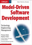
In practice a layered model has proven to be most useful in software architectures. This structure can be found in some form in almost all well-structured software systems. Figure 7.3 shows this.
Figure 7.3 An architecture reference model.
The operating system and the programming language form the basis of each architecture. Building on this foundation, there is usually a technical framework that provides essential technical services, often implemented using middleware. These can be persistence, transactions, distribution, workflow, GUIs, scheduling, or hardware access. The question of which services are actually offered by this layer depends on the technical domain, such as real-time embedded, business, or peer-to-peer. Typical examples of such frameworks are J2EE and .NET in the enterprise field, and Osek + Standard Core in the field of embedded systems, mostly in the automotive sector.
It is typical to find a framework based on this layer that provides the foundation for the functional/professional domain:
- Entities represent concepts that possess an identity and a lifecycle – for example, each customer has an identity that must be preserved as long as the object exists.
- Value objects represent values. Amounts of money in banking, for example, or coordinates sets in a GPS application are good examples of value objects. Value objects do not have an identity: only their value is relevant, and two objects with the same value are considered identical.
- Business rules and Constraints. Here, the domain’s basic rules that cannot be assigned to an Entity are captured, for example that drivers of cars must always be older than eighteen, or that the amount of money in a transaction can never be negative.
- Services. Basic services are defined here that cannot be assigned to an Entity, for example the execution of a transaction, or the validation of a complex document structure in editorial systems.
Even though this list is based on Enterprise/Business systems, these statements are also valid for technical or embedded systems, although the terminology and the software/technical implementations are different in that context. The actual application builds on these frameworks.
7.6 Balancing the MDSD Platform
In the context of MDSD the reference model is very important – not only for structuring the target architecture, but specifically to define the boundaries of the MDSD platform, which is part of the target architecture. Finally, the application models must be mapped to the MDSD platform using transformations in order to make them executable. The larger the gap between the concepts of the MDSD domain and the concepts of the MDSD platform, the more complex the necessary transformations will be. This should be avoided, especially since complexity at the metalevel is harder to cope with than complexity at the concrete level of the target architecture. To decrease complexity, the MDSD domain and the MDSD platform should be as close to each other as possible – more precisely, the MDSD platform should ‘meet the MDSD domain halfway’. We also call such a platform a rich, domain-specific platform.
As far as the reference model is concerned, we now have several basic options for reducing the conceptual distance between domain and platform:
- MDSD domain and platform are located at the level of the reference model’s technical platform. This would for example lead to a choice of a UML profile for J2EE as DSL and J2EE as an MDSD platform. Such a domain architecture is of course feasible, but due to its limited abstraction level it does not use the full potential for automation: the bulk of a modeled application must be programmed manually. On the other hand, the MDSD domain is quite versatile – the domain architecture allows for the production of very different applications.
- MDSD domain and platform are at the level of the target architecture’s concepts. AC-MDSD is an example of this, as in Chapter 3’s case study. Here the architectural realization patterns of the functional platform are derived from the reference model for the DSL definition, as well as for the MDSD platform. In this case, the domain is less versatile, but its abstraction level is increased and thus its potential for automation is higher.
- MDSD domain and platform are at the level of the functional/professional platform of the reference architecture. In this case the functional/professional platform of the reference architecture becomes the MDSD platform. The domain is significantly less versatile than in the architecture-centric case, but automation can reach 100% without a problem.
We recommend the last two options. Specifically, it makes sense to build cascades where a functional/professional MSDD platform is built on top of an architecture-centric domain architecture. This approach is illustrated in the case study in Chapter 16.
7.6.1 Examples
Where the boundary of the MDSD platform is drawn in practice, and where in each particular case, depends typically on how much flexibility is needed in the specific context. Here are some examples:
- Typical ingredients of an architecture-centric MDSD platform for e-business systems are flow control or workflow engine, persistence framework, superclasses for GUIs, activities and entities and so on, and technical standard infrastructures such as J2EE containers and relational databases. All these artifacts are identical for each software system of the architecture-centric MDSD domain.
- In the context of a system family for radio telescopes in the astronomy domain, stars, galaxies, or planets are relevant entities. Their properties usually don’t change much, therefore these entities are part of the MDSD platform. Also, many ‘business rules’ are static in this case because they are based on the laws of physics.
- For insurance companies, insurance products are relevant entities. These are actually very different and change frequently. Such entities are conveniently described using the DSL, and their implementation is generated. Other core entities such as Person or Account can be part of the MDSD platform.
- In the context of a component infrastructure for distributed embedded systems, even the technical platform, the middleware, is generated based on predefined system constraints and topology definitions and is thus not part of the MDSD platform. Even if all basic entities or the technical infrastructure are generated, a domain-specific basic framework typically exists as part of the MDSD platform. In an embedded system, for example, we might find bus drivers and marshalers to serialize a data structure for transport across the network.
We recommend that you expand the power of your MDSD platform incrementally in the course of your project, in keeping with your growing understanding of the domain. This will reduce the scope and complexity of the code developers have to write to customize the framework, which must either be generated or even partially be written manually.
The general rule is that generic and generalizable code segments should be part of the MDSD platform. Existing frameworks are usually also well-suited for integration in the MDSD platform.
7.6.2 Integration of Frameworks
The use of complex frameworks can be significantly simplified and sped up through the use of customized DSLs. This is often overlooked by framework purists. In many cases, only a DSL and a model-driven approach can guarantee that a framework is used correctly – that is, as intended by its inventor. Today’s implementation languages do not possess any particularly powerful mechanisms for preventing faulty framework use. By definition frameworks entail a strong interlocking of framework implementation and framework use, which often contradicts the encapsulation principle. The domain can be clearly isolated from the applied implementation platform only via a DSL.
On the other hand, highly configurable, generic frameworks attract the danger of overburdening their implementation, making them difficult to maintain and hard to debug. This should be considered in MDSD platform construction.
The key to successful MDSD platform design is an iterative, incremental approach, as is described in Chapter 13. The development of powerful frameworks in large, independent projects that have no direct iterative connection with real-life application development projects will inevitably result in failure. Instead, small frameworks combined with code generation offer a solid basis for iterative development. When code generation – that is, writing templates – becomes too difficult, it is worth enhancing the frameworks and implementing more features with their help. Vice versa, if the implementation of the framework becomes overly complicated, or its runtime performance deteriorates, the use of generative techniques will often lead to elegant solutions.
7.7 Architecture Conformance
A good target architecture can exhibit its advantages only if it is not ignored or circumvented in the daily project routine. Traditional methods such as reviews and excessive documentation are not easily scalable when working with bigger teams. For generated code, MDSD per se offers the solution, particularly because the aspects of the architecture that are described using the models are laid down in the form of transformation rules.
The component example described in Chapters 6 and 16 serve as an example of how one can enforce or control the observation of specific characteristics of the target architecture in manually-programmed parts of systems as well. We can to demonstrate which effects the use of these options can have on the target architecture. Figure 7.4 helps to illustrate this example once more:
Figure 7.4 An example of dependencies between components.

The figure shows, among other things, that the component SMSApp depends on the components MenuUtilities, TextEditor, and GSMStack via their interfaces. The explicit description of such dependencies and their management is an essential aspect of architecture in large projects. Therefore, it should be impossible for a component or its implementation code to access interfaces or components for which no dependency is defined in the model. This must actually be ensured in large projects, ideally by automation. It can be achieved with MDSD, particularly through its aspect of code generation. The following code segment shows a ‘classic’ implementation of a component: access to other components is obtained by querying the corresponding reference from a central component factory:
public class SMSAppImpl {
  public void doSomething() {
    TextEditor editor = (TextEditor)
             Factory.getComponent(“TextEditor”);
    editor.setText( someText );
    editor.show();
  }
}
It is not easy to ensure that the developer does not illegally obtain other references from the factory. This can only be accomplished through reviews or other tools such as AspectJ. However, if development is model-driven, there is another option: for each component, a component context [VSW02] can be generated, which exclusively permits access to those components or interfaces to which a dependency is given in the model. The following code illustrates this:
public interface SMSAppContext
        extends ComponentContext {
public TextEditorIF getTextEditorIF();
  public SMSIF getSMSIF();
  public MenuIF getMenuIF();
}
public class SMSAppImpl implements Component {
  private SMSAppContext context = null;
  public void init( ComponentContext ctx) {
    this.context = (SMSAppContext)ctx;
  }
  public void doSomething() {
    TextEditor editor =
            context.getTextEditorIF();
    editor.setText( someText );
    editor.show();
  }
}
Now the developer can no longer autonomously get arbitrary references – they can only access those for which accessor operations exist in the component context. These access operations are generated from the model. If the developer wishes to access other interfaces, they must include them in the model, otherwise the necessary accessor method will not be available in the code. This guarantees that a component only possesses those dependencies that it explicitly declares in the model. A more extensive infrastructure is required, of course: for example, ‘someone’ must call the operation init() and provide the correct context object. In component-based systems this is the task of a container – in this case the runtime system, which is in charge of the component’s lifecycle.
This approach has the pleasant side-effect that in modern IDEs one is conveniently informed, via code completion, of which operations are present in the component context – thus information on the legal dependencies can be found directly in the code, making it easier for the developer to observe the architecture’s rules!
The example given above also shows what effects the use of MDSD has on the architecture. It would never occur to a developer to provide a separate context class for each component if this had to be implemented manually. The use of MDSD therefore opens up additional architectural alternatives. It is pivotal to know about and use these alternatives when the target architecture is defined.
7.8 MDSD and CBD
Component-Based Development (CBD) is a popular metaphor for building complex systems, as is Service-Oriented Architecture, which is covered in Section 7.8. We have already covered some aspects of the interplay between MDSD and CBD in the previous sections: in this section we want to take it a step further. From our experience in development projects, we find that we almost always start by modeling the component structure of the system to be built. To do that, we start by defining what a component actually is — that is, by defining a metamodel for component-based development. Independent of the domain in which the development project resides, these metamodels are quite similar across application domains – insurance, e-commerce, radio astronomy, and so on (as opposed to technical domains such as persistence, transaction processing, security.) We therefore show parts of these metamodels here to give you a head start when defining your own component architecture. This ties in nicely with the architectural process proposed in Section 13.4.
7.8.1 Three Viewpoints
It is useful to look at a component-based system from three viewpoints, and idea that we enlarge on in the case study on enterprise systems in Chapter 17.
The Type Viewpoint
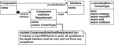
The type viewpoint describes component types, interfaces, and data structures. A component provides a number of interfaces and references a number of required interfaces. An interface owns a number of operations, each with a return type, parameters, and exceptions. Figure 7.5 shows this.
Figure 7.5 The metamodel for components, interfaces, and their dependencies.

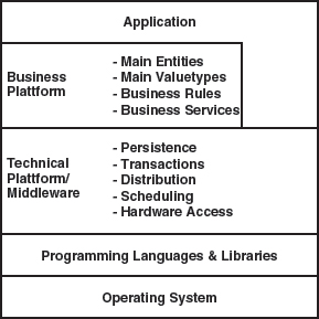
To describe the data structures with which the components work (Figure 7.6), we start out with the abstract type Type. We use primitive types as well as complex types. A complex type has a number of named and typed attributes. There are two kinds of complex types. Data transfer objects are simple structs that are used to exchange data among components. Entities have a unique ID and can be made persistent (this is not visible from the metamodel). Entities can reference each other and thus build more complex data graphs. Each reference has to specify whether it is navigable in only one or in both dimensions. A reference also specifies the cardinalities of the entities at the respective ends.
Figure 7.6 The metamodel for data structures.
The Composition Viewpoint
This viewpoint, illustrated in Figure 7.7, describes component instances and how they are connected. A configuration consists of a number of component instances, each knowing their type. An instance has a number of wires: a wire is an instance of a component interface requirement. Note the constraints defined in the metamodel:
- For each component interface requirement defined in the instance’s type, we need to supply a wire.
- The type of the component instance at the target end of a wire needs to provide the interface at which the wire’s component interface requirement points.
Using the type and composition viewpoints, it is possible to define component types as well as their collaborations. Logical models of applications can be defined. You could, for example, use UML to render these two kinds of models, generate skeleton classes, and then implement the application logic in subclasses. From the composition viewpoint, you can generate or configure a container that instantiates the component instances. Unit tests that verify the application logic can be run here.
Figure 7.7 Component instances and their connections in the composition metamodel.

The System Viewpoint
This third viewpoint as shown in Figure 7.8 describes the system infrastructure onto which the logical system defined with the two previous viewpoints is deployed.
Figure 7.8 The metamodel for systems.

A system consists of a number of nodes, each one hosting containers. A container hosts a number of component instances. Note that a container also defines its kind – this could be things like CCM, J2EE, Eclipse or Spring. Based on this information, you can generate the necessary ‘glue’ code to run the components in that kind of container.
The node information, together with the connections defined in the composition model, allows you to generate all kinds of things, from remote communication infrastructure code and configuration to build and packaging scripts.
7.8.2 Viewpoint Dependencies
You may have observed that the dependencies among the models are well-structured. Since you want to be able to define several compositions using the same components and interfaces, and since you want to be able to run the same compositions on several infrastructures, dependencies are only legal in the directions shown in Figure 7.9.
Figure 7.9 Dependencies among the viewpoint models.
7.8.3 Aspect Models
The three viewpoints described above are a good starting point for modeling and building component-based systems. However, in most cases these three models are not enough. Additional aspects of the system have to be described using specific aspect models that are arranged around the three core viewpoint models, as illustrated in Figure 7.10.
Figure 7.10 Arranging the aspect models around the three core viewpoint models.

The following aspects are typically handled in separate aspect models:
- Persistence
- Authorization and Authentication (important in enterprise systems)
- Forms, layout, pageflow (for Web applications)
- Timing, scheduling and other quality of service aspects (especially in embedded systems)
- Packaging and deployment
- Diagnostics and monitoring
The idea of aspect models is that the information is not added to the three core viewpoints, but rather is described using a separate model with a suitable concrete syntax. Again, the metamodel dependencies are important: the aspects may depend on the core viewpoint models and maybe even on one another, but the core viewpoints must not depend on any of the aspect models. Figure 7.11 illustrates a simplified persistence aspect metamodel.
Figure 7.11 The metamodel for the (relational) persistence aspect.

7.8.4 Variations
The metamodels we describe above cannot be used in exactly this way in every project. Also, in many cases the notion of what constitutes a component needs to be extended. So there are many variations of these metamodels. However, judging from practice, even these variations are limited. In this section we want to illustrate some of these variations.
- You might not need separate interfaces. Operations could be added directly to the components. As a consequence, of course, you cannot reuse the interface ‘contracts’ separately, independently of the supplier or consumer components.
- Often you’ll need different kinds of components, such as domain components, data access (DAO) components, process components, or business rules components. Depending on this component classification you can come up with valid dependency structures between components. You will typically also use different ways of implementing component functionality, depending on the component types (see also Section 7.8.5).
- Another way of managing dependencies is to mark each component with a layer tag, such as domain, service, gui, or facade, and define constraints on how components in these layers may depend on each other.
- Hierarchical components, as illustrated in Figure 7.12, are a very powerful tool. Here a component is internally structured as a composition of other component instances. Ports define how components may be connected: a port has an optional protocol definition that allows for port compatibility checks that go beyond simple interface equality. While this approach is powerful, it is also non-trivial, since it blurs the formerly clear distinction between type and composition viewpoints.
Figure 7.12 The metamodel for hierarchical components.

- A component might have a number of configuration parameters – comparable to command line arguments in console programs – that help configure the behavior of components. The parameters and their types are defined in the type model, and values for the parameters can be specified later, for example in the composition or the system models.
- You might want to say something about whether the components are stateless or stateful, whether they are thread-safe or not, and what their lifecycle should look like (for example, whether they are passive or active, whether they want to be notified of lifecycle events such as activation, and so on).
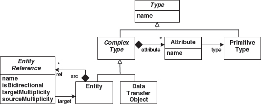
- It is not always enough to use simple synchronous communication. Instead, one of the various asynchronous communication patterns, such as those described in [VKZ04], might be applicable. Because using these patterns affects the APIs of the components, the pattern to be used has to be marked up in the type model, as shown in Figure 7.13.
Figure 7.13 Asynchronous communication.
- In addition to the communication through interfaces, you might need (asynchronous) events using a static or dynamic publisher/subscriber infrastructure. It is often useful that the ‘direction of flow’ of these events is the opposite of the uses-dependencies discussed above.
- The composition model connects component instances statically. This is not always feasible. If dynamic wiring is necessary, the best way is to embed the information that determines which instance to connect to at runtime into the static wiring model. So, instead of specifying in the model that instance A must be wired to instance B, the model only specifies that A needs to connect to a component with the following properties: needs to provide a certain interface, and for example offer a certain reliability. At runtime, the wire is ‘deferenced’ to a suitable instance using an instance repository. This approach is similar to CORBA’s trader service.
- Finally, it is often necessary to provide additional means of structuring complex systems. The terms business component or subsystem are often used. Such a higher-level structure consists of a number of components. Optionally, constraints define which kinds of components may be contained in a specific kind of higher-level structure. For example, you might want to define that a business component always consists of exactly one facade component and any number of domain components.
7.8.5 Component Implementation
Component implementation typically happens manually. This means that developers add manually-written code to the component skeleton, either by adding the code directly to the generated class, or – a much better approach – by using other means of composition such as inheritance or partial classes. The main reason is that action languages that support the generic formulation of application logic at the model level are still not widely supported. However, using a generic action language to describe the behavior of structural artifacts (such as a class’s operations or a state’s actions) is only one alternative. There are other means of describing application logic, some of which we outline below. All have in common that instead of providing a generic way of modeling all kinds of behavior in models, they use notations that are specific to the kind of behavior that should be specified.
- Behavior that is very regular can be implemented using the generator, after parametrizing it in the model by setting a small number of well-defined variability points. Feature models are good at expressing the variabilities that need to be decided so that an implementation can be generated.
- For state-based behavior, state machines can be used.
- For things such as business rules, you can define a DSL that directly express these rules and use a rules engine to evaluate them. Several rule engines are available off-the-shelf.
- For domain-specific calculations, such as those common in the insurance domain, you might want to provide a specific textual notation that supports the mathematical operations required for the domain directly. Such languages are often interpreted: the component implementation technically consists of an interpreter that is parametrized with the program it should run.
Note that we are not generally arguing against Action Semantics Languages (ASLs), we just want to point out that they don’t provide domain-specific abstractions, being generic in the same way as for example UML is a generic modeling language. However, even if you use more specific notations, there might still be a need to specify small snippets of behavior generically. A good example are actions in state machines.
To combine the various ways of specifying behavior with the notion of components, it is useful to define various kinds of components, using subtyping at the metalevel, that each have their own notation for specifying behavior. The case study in Chapter 17 illustrates this approach, and the idea is also illustrated in Figure 7.14.
Figure 7.14 Subtypes of component to host various kinds of behavioral specifications.

Since component implementation is about behavior, technically, it is often useful to use an interpreter encapsulated inside the component. Such an ‘interpreter component’ is still a component just as any other. Their introduction however raises an issue that needs to be addressed: How does the interpreter know which script to execute?
There are basically three different approaches to this. Either the component always executes the same script, the entire script is passed to the component as a parameter, or some sort of identifier for the script is passed to the component. This can be done either as part of the configuration process when the component is created, or it can be done with every method call. For more details on interpretation, see Section 8.4.
As a final note, be aware that the discussion in this section is only really relevant for application-specific behavior, not for all implementation code. Huge amounts of implementation code is related to the technical infrastructure – remoting, persistence, workflow and so on – of an application, and can be derived from the (structural) models.
7.9 SOA, BPM and MDSD
Service-Oriented Architectures (SOA) and Business Process Management (BPM) are two highly hyped topics in today’s IT world. This section takes a MDSD-centric view of them and discusses their possible synergy.
7.9.1 SOA
There is no commonly agreed definition of what SOA actually means. Some people equate SOA merely to ‘using Web Services’. In fact SOA is at least driven by Web Service technology, including BPEL (Business Process Execution Language). From our perspective, SOA has nothing to do with specific technologies (WSDL, SOAP, HTTP), but rather constitutes a set of architectural best practices for building large, scalable, and composable systems. A well-constructed component-based architecture with well-defined interfaces and clear-cut component responsibilities can quite justifiable be considered SOA. Components are a natural choice for the building blocks that provide and consume services. The industry realizes this and currently defines a standard for Service-Component Architectures [SCA].
However, looking at SOA a bit more closely, it is possible to identify a number of important properties that cannot readily be found in (most) component-based systems:
- Service interactions are message-oriented, or document centric. Instead of defining rigidly typed interfaces, document structures (schemas) are defined that serve as the basis for interactions. Done right, this can make evolution of message structures and versioning much simpler.
- The interaction patterns – valid sequences of messages – are explicitly defined. Interactions are often conversational – conversational session state is kept ‘on both sides’ of a service interaction. These features are the basis for orchestration among services. Usually, interactions are asynchronous.
- Quality of service aspects are explicitly addressed. Service providers do not just provide a certain services’ functionality, they provide the functionality with a defined service level in terms of performance and reliability.
- Service descriptions and characteristics are available at runtime. Using service registries, systems can be assembled dynamically.
- Often, services are interoperable – they can be used by systems implemented on various platforms.
In addition to these characteristics, services should be designed to be coarse-grained and encapsulate functionality relevant from a business perspective – although nobody can say what this really means! Services are typically but by no means exclusively used by explicitly-modelled business processes. Finally, like any good IT system, they are secure, transactional and manageable.
Opinions differ over whether these characteristics are really so different from today’s well-constructed enterprise systems. However, what is obvious in our view is that models play a central role in the definition and operation of service-oriented systems:
- Message schemas are data structure models that specify required and optional content, as well as how message formats change during the evolution of a service.
- Interaction patterns between services are defined using models: for example, communicating state machines are useful notations to describe valid sequences of messages as well as exceptional cases.
- The levels of quality provided by a service provider, and required by a service consumer, are basically models that are evaluated and checked for compatibility.
- The runtime repository basically makes the model information available to runtime queries.
- Finally, interoperability can be achieved by generating implementations and bindings for various platforms from the same authoritative model.
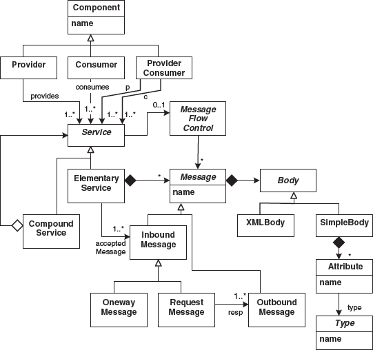
So the central idea to SOA in our view is to establish an interface contract first! The first thing you specify when developing systems is how the communication partners actually interact – which is independent of communication technology and independent of implementation platform. Rather, you specify message formats, interaction patterns, and quality of service contracts on an abstract and formal level. That basically means: use MDSD based on the architectural process described in Section 13.4.
Figure 7.15 shows a simplified metamodel for services. It also shows how to connect the SOA ‘world’ with the component ‘world’ described in the previous section.
In the context of SOA you often see two pictures showing a spaghetti-like system with all those interconnections labelled ‘old’ on one side, and a nicely-ordered set of components connected through a single bus to which all components are attached, labelled ‘service-oriented’ on the other. This leads people to think that in SOA all systems must be physically connected through a single technical infrastructure often Web Services). Nothing could be more wrong! If you connect all kinds of systems through the same infrastructure, you will have a hard time addressing non-technical requirements such as throughput, interoperability, or performance. The bus you often see on such PowerPoint slides must be interpreted as a ‘logical bus’ – that is, a common, model-based communications infrastructure through which messages can be mapped to various communication technologies, and service endpoint be implemented on various platforms.
Figure 7.15 A simplified metamodel for services.
7.9.2 BPM
As with SOA, there is no commonly-agreed definition of BPM, but there seems to be a kind of consensus among industry leaders:
- BPM deals with design and control of (rapidly changing) business processes, which leads to tasks of structuring, automation, and optimization of these artifacts.
- Business processes connect people with available information technology and material.
- Process definitions and implementations have to be flexible, so that you can change them to meet the value creation chains of your business.
- BPM respects the complete lifecycle of a business process, which consists of definition (standards-based graphical modeling, process simulation, business rules), creation (code generation), execution (integration, automation and workflow), monitoring (business activity monitoring, dashboards) and optimization (ability to adjust business rules dynamically).
- BPM is not a product and none of the following single product categories can be said to cover BPM completely: workflow, enterprise application integration (EAI), business activity monitoring (BAM), rules engines, process-simulations. Ideally they can be part of a system that supports BPM (BPMS).
Some standards exist, such as BPMN (Business Process Modeling Notation [BPMN] and BPML (Business Process Modeling Language [BPML]) from OASIS [OASIS], or XPDL (XML Process Definition Language, [XPDL]) from WfMC [WfMC]. In practice we observe quite a confusion, because respective tool suppliers often try to ‘improve’ their products with a BPM label. As a consequence BPM products essentially suffer from not being comparable at all.
An isolated MDSD-view of BPM should be obvious: models and transformations are already essential concepts of BPM in order to achieve it goals.
7.9.3 SOA and BPM
An intersection of SOA and BPM exists: modeling and specification of business processes on one hand, and respective infrastructure software (middleware) on the other. SOA covers business process modeling through BPEL (Business Process Execution Language, [BPEL]) which is based on and coupled to Web Service technology. BPM covers business process modeling through more abstract language concepts and (graphical) notations (BPML/N). So from a specific point of view we can say that SOA is a bottom-up evolution and BPM a top-down one. The middleware in the intersection placed by SOA is mainly referred to as ESB (Enterprise Service Bus), which should be viewed as a logical bus for messaging, service composition, and orchestration, as we pointed out in Section 7.9.1. BPM, on the other hand, comes with BPEs (Business Process Engine) or BPMS (see above).
It is not enough to say that the intersection between these disciplines is not empty: there is even conceptional mismatch in their intersection. For example, BPEL suffers (for now) from concepts of human resources involved in a workflow, so essentially BPMN/L cannot be mapped to BPEL yet.
Certainly we can hope and expect that these mismatches will be eliminated some day by a proper standardization process. At least until then a distinguished approach may serve as a way to find a useful synthesis for SOA and BPM – the principle of Separation of Concerns. BPM needs SOA in order to be as flexible as required, but not the other way round. If there is a decision in your company to have both architectural concepts combined in an enterprise architecture, it may be reasonable to use BPM concepts with respective middleware for the business process layer, and SOA concepts with respective middleware on a business service/component layer, which is placed logically below the business process layer. In that case, you do not use SOA (for example, BPEL) to model and maintain business processes.
To conclude this section we will try to place MDSD/MDA in the context of a synthesis of SOA and BPM:
- MDSD/MDA can provide standards-based modeling of business processes (that is, standardized, MOF-based metamodel definition for BPM) and respective ‘generic’ notations (for example BMPN as a UML-profile). The OMG has already set up corresponding activities.
- MDSD/MDA can provide a sound and complete architecture-centric MDSD-production line that supports all layers (business processes, service/components, entities, persistence) of an enterprise architecture in a consistent and defined way. It can take advantage from the knowledge of all these layers and their interaction in order to check comprehensive constraints and generate infrastructure code even between the layers. Hooks for version handling of services or business process definitions and support for transactions or compensations may be generated. Different model-to-code transformations may be implemented to realize a ‘fan out’ that is capable of adopting different platform technologies. But before you can automate an architecture you have to define and build it – at least partially (see Section 13.4).
- Some people claim that MDSD is useful for service enabling – that is, SOA-oriented re-engineering of monolithic legacy applications in to make them usable for BPM – since models derived from existing applications can serve as the essence of those applications. We think that this idea is quite ambitious but at least worth mentioning.
1 This is a uses relation: the platform is used by the (generated) software products, but it doesn’t belong to them.
2 We use the term ‘functional/professional’ throughout the book as an English version for the German word fachlich. The word does not have a direct equivalent in English: in German we speak of technischen domains and fachlichen domains as their opposite. Technisch clearly deals with technical issues such as scalability, persistence, transactions, load balancing, security. A functional/professional (fachlichen) domain is one that deals with application-orientated issues, for example insurance, radio astronomy, tax calculation, engine management and so on.