
Chapter 6
Metamodeling
Metamodeling is one of the most important aspects of Model-Driven Software Development. Metamodeling knowledge is needed for dealing with the following MDSD challenges:
- Construction of domain-specific modeling languages (DSLs): the metamodel describes the abstract syntax of such a language (see Chapter 4).
- Model validation: models are validated against the constraints defined in the metamodel.
- Model-to-model transformations: such transformations are defined as mapping rules between two metamodels.
- Code generation: the generation templates refer to the metamodel of the DSL.
- Tool integration: based on the metamodel, modeling tools can be adapted to the respective domain.
This list helps to justify why we dedicate an entire chapter to this subject.
6.1 What Is Metamodeling?
Metamodels are models that make statements about modeling. More precisely, a metamodel describes the possible structure of models – in an abstract way, it defines the constructs of a modeling language and their relationships, as well as constraints and modeling rules – but not the concrete syntax of the language. We say that a metamodel defines the abstract syntax and the static semantics of a modeling language (see Chapter 4). Vice versa, each formal language, such as Java or UML, possesses a metamodel.
Metamodels and models have a class-instance relationship: each model is an instance of a metamodel. To define a metamodel, a metamodeling language is therefore required that in turn is described by a meta meta model. In theory, this abstraction ‘cascade’ can be continued ad infinitum, but in practice other steps are taken, as we will soon learn.
In the context of MDSD, the domain’s DSL is defined by a metamodel. The concrete syntax – that is, the concrete form of the textual or graphical constructs with which the modeling is done – is conceptually irrelevant: it must merely render the metamodel in an unambiguous way. The distinction between abstract and concrete syntax is very important here, because the metamodel (and not the concrete syntax) is the basis for the automated, tool-supported processing of models. On the other hand, a suitable concrete syntax is the interface to the modeler – without it, no models could be created – and its quality decides what degree of readability the models have1.
As a consequence of this decoupling, the metamodel and the concrete syntaxes of a DSL can maintain a 1:n relationship: the same metamodel can be realized by a graphical as well as a textual syntax.
Figure 6.1 Relationship between the real world, model and metamodel.

In principle models can be described in an arbitrary modeling language. Language selection should be made based on the language’s suitability for the domain to be described. In real life, this decision is often determined by the question of whether or not practically usable tools are available for the modeling language, which means that today UML is used for modeling in many cases. It is therefore of particular relevance to look at metamodeling in the context of UML.
The meta relationship is always to be seen relative to a model. An absolute definition of the term metamodel does not make sense in theory, but in practice it is quite useful. For this reason, the OMG defines four metalevels. These are shown in Figure 6.2 and are described further in the following sections.
Figure 6.2 The four metalevels of OMG.
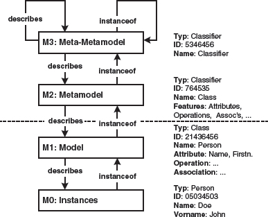
Below the dashed line we find ourselves on familiar ground as software developers. In M1, in the model, a class is defined. This class is given a name, Person, and a number of attributes, in this case name and first name. Instances of this class are created in M0, usually at program runtime: in the example in the figure, the person with the (internal) ID 05034503, the last name Doe and first name John – or more precisely, the attributes name and first name have the value Doe and John, respectively, for this instance. During the instantiation of a class, therefore, values are assigned to attributes of the class. Note that a class can have more than one instance. The model (here: the class Person) is defined via a language – in our case UML – even though this is not shown in Figure 6.2.
We now move up one metalevel. In M2, the metamodel, the constructs that are used in the M1 model are defined. The elements of the M1 model are thus instances of the elements of the metamodel at the M2 level. Since we use classes in the M1 model, the construct Class must be defined in M2. This is actually the case in the UML metamodel2.
The construct Class in the UML metamodel is now an instance of the meta meta element MOF Classifier. MOF classes are defined in M3. The meta object facility (MOF) is the OMG’s meta meta model (see Chapter 12). The MOF serves to define modeling languages at M2, such as for example UML. The idea behind this is that UML will not remain the only modeling language, but that additional domain-specific and possibly standardized modeling languages will be defined that are based on the MOF. The MOF is also able to define non-OO modeling languages. We provide an example of this ability below.
There is no metalevel in the OMG model above the MOF – basically, the MOF defines itself.
Figure 6.3 shows a (simplified and incomplete) excerpt of the MOF.
Figure 6.3 An excerpt from the MOF.

As the name MOF implies, this is a meta meta language based on the object-oriented paradigm. For this purpose, the MOF borrows the UML’s class core, thus using the same concepts and the same concrete syntax.
Whenever we extend the UML metamodel, for example through a derivation of a metaclass MyMetaClass from UML::Class, we do this by means of the MOF. The inheritance relationship between the two metaclasses is the inheritance relationship as it is defined in the MOF::Classifier or its super class MOF::GeneralizableElement, respectively.
Figure 6.4 Metamodel expansion in relation to the MOF.

6.2 Metalevels vs. Level of Abstraction
Models can have different relationships to each other. This chapter illuminates the meta relationship, which states that the metamodel defines the concepts with which a model can be created.
On the other hand, models can also be located on different abstraction levels, even though they are located on the same metalevel. Typically, transformations are used to map models at a higher abstraction level to models with a lower abstraction level. Each of the models is (inevitably) an instance of a metamodel. The metamodels of the two models are therefore different, yet the models as well as the metamodels can be found on the same metalevel. Figure 6.5 shows this.
Figure 6.5 Meta versus abstract

6.3 MOF and UML
UML is an instance – an application – of the MOF. Various details must be considered.
First, UML existed before the MOF. UML was originally not formally defined – that is, it was defined purely verbally. The MOF was defined later to specify UML formally based on the MOF. The problems that emerged from this sequence were cured in later UML revisions, so that UML can now be called a MOF language in good faith.
The notation for MOF models is the concrete syntax of UML. Occasionally, this can lead to confusion. Formally, this problem can be solved through the specification of namespaces/packages for model elements, yet the potential for confusion remains.
It should also be observed that the MOF contains a number of model elements that are also present in UML. For example, both languages possess an element called Class. Even though the elements have the same name and often superficially describe the same feature, they are not identical – if only because they are located on different metalevels.
6.4 Extending UML
In the context of software development, often one will not start by defining a completely new M2 language based on the MOF. Rather, one will start with the UML metamodel and extend it as needed. To carry out this extension, there are three options:
- Extension based on the UML’s formal metamodel.
- Extension using stereotypes/profiles (by means of UML 1.x).
- Extension using stereotypes/profiles (by means of UML 2).
We look at each of these alternatives in the following sections. In practice, one would mainly use the stereotype/profile mechanisms, due to the number of available tools for the definition of UML-based metamodels.
6.4.1 Extension Based on the Metamodel
This type of extension extends the UML’s metamodel. To this end we apply, as always in modeling, the language of the next-higher metalevel, which in this case is the MOF. Such an extension can take place within a tool only if the tool possesses an explicitly-represented disclosed MOF-based metamodel.
To define, for example, one’s own kind of class, you would create a new M2 class that inherits from the UML metaclass UML::Class. Figure 6.6 illustrates this process.
Figure 6.6 UML adaptation through extension of the UML metamodel.

Here, a new language construct is defined – the CM::Component. This is a subclass of the Class element of the UML. As we explained in the previous section, the inheritance mechanism of the MOF is used here, since after all we are dealing with a MOF model of the UML.
It is theoretically possible to assign a graphical representation – a concrete syntax – to each language element we define, as is illustrated by (e) in Figure 6.7. This is often impossible in practice, however, because the tool does not support it. Other types of representations can be used, most of them based on stereotypes.
Figure 6.7 Representation of the metamodel expansion through stereotypes.
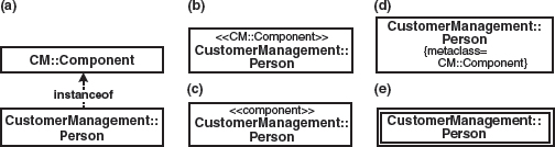
Figure 6.7 (a) shows a CustomerManagement::Person class as a direct instance of the metaclass CM::Component. (b) uses the name of the metaclass as a stereotype, while (c) uses an abbreviation agreed by convention, (d) a tagged value stating the metaclass, and (e) an individual graphical notation. The approach (c) has proved to be the most practicable in real life, while (e) is a viable alternative if the tool allows this option.
The CM::Component cannot be distinguished from a UML class – apart from its formal type – because it neither adds nor overwrites any attributes and operations, and does not define constraints. This is not necessarily always true: we can define new attributes for our own metaclass. These will typically be represented by tagged values in the target models, as can be seen in Figure 6.8.
Figure 6.8 Tagged values as concrete syntax of metamodel attributes.

The type of adaptation of modeling languages introduced here – the extension of the metamodel using the MOF – doesn’t only work in a UML context, but also for all other MOF-based modeling languages. The mechanism based on profiles, which is introduced further below, is in contrast restricted to UML, since it is defined as part of UML itself.
It is important to point out that there is no switching to another metalevel when the metamodel is extended via inheritance. Figure 6.9 shows this.
Figure 6.9 Inheritance inside the M2 layer.

Figure 6.9 also shows that the prefix meta is in principle always relative to a model3. When a metamodel is extended, the origin is called the basic metamodel.
6.4.2 Extension With Stereotypes in UML 1.x
Extension with stereotypes is a UML-specific functionality, defined as part of the profile mechanism. This means that the UML itself is a way in which the UML metamodel can be extended to a certain extent, or, more precisely, be specialized without being required to using the means of modeling language definition provided by the MOF. One reason for this is probably that when UML was originally defined, the MOF did not exist, so some other means of extension had to be provided. This extension mechanism works with UML only, so other MOF-based languages must define their own extension mechanisms.
Figure 6.10 shows the definition of the stereotype CM::Component, including the tagged value transactional.
Figure 6.10 Definition of a stereotype in UML 1.x.

It is important to note that the diagram in Figure 6.10 is formally an M1 model of the MOF hierarchy, since it is a UML model, and not a part of the UML’s metamodel. Semantically, it is at the M2 level, because quite clearly a UML metaclass (UML::Class) is specialized here.
Serious limitations or this approach when compared to the metamodel’s extension via MOF are that tagged values are not typed (all tagged values are Strings) and no new meta associations between existing metamodel classes or stereotypes can be defined. The advantage, however, is its usability in the field of generic UML tools.
6.4.3 Extension With Profiles in UML 2
With the definition of UML 2.0 the stereotype mechanism has been extended and placed in the context of a more comprehensive profile mechanism (see also Section 6.5 and Chapter 12). The concept of extensions is pivotal here. An extension is a new symbol, and thus a new language construct, of UML. It is rendered as a filled inheritance arrow, as shown in Figure 6.11.
Figure 6.11 Definition of a stereotype in UML 2.x.
It should be emphasized that we are not dealing with inheritance, implementation, stereotypical dependency, or association here, but with a completely new UML language construct that is also defined formally in the UML metamodel.
A stereotype can have attributes. As in UML 1.x, these are rendered as tagged values in the model in which the stereotype is used (see Figure 6.12). From UML 2 onwards a tagged value can be assigned a type, thus all tagged values are no longer strings per se.
Figure 6.12 Tagged values in UML 2.0.

Another difference between UML 2.0 and UML 1.x is that a model element can now have multiple stereotypes simultaneously. It then possesses the attributes of all stereotypes as tagged values4.
6.5 UML Profiles
Profiles support adaptation or extension of UML to fit professional or technical domains. One might also say that UML is not a language, but a language family: in this case, UML profiles are elements – concrete languages – in this family. The objective is that UML tools and generators can process profiles like plug-ins: one first loads a specific profile, then modeling can take place based on the profile. To make this work smoothly in practice, a clear-cut separation between model, profile, transformations and tools is mandatory. For this purpose, the OMG defines a profile mechanism for the UML.
Principally, UML profiles consist of three kinds of artifacts: stereotypes, tagged values, and constraints5. Profiles can extend UML’s valid constraints – that is, further constrain them – but cannot relax their restrictions. In UML 1.x the construct of the profile is only defined verbally. In UML 2.0, the concept of the profile based on the UML metamodel is defined formally. Here we also find the definition of the extension concept mentioned in the previous section.
Figure 6.13 shows the metamodel of the profile definition of the UML 2.0 specification – which itself can serve as an example of metamodeling. We omitted explicitly marking up the namespace for each element, since it’s all part of the UML metamodel6.
Figure 6.13 Metamodel of the profile concept.

According to Figure 6.13, a profile is first defined as a specialization of a UML::Package. Packages can be profiled through the use of a ProfileApplication, a specialization of Package-Import. More loosely one could say that when a package imports a profile package, this means that the profile is applied to the importing package. A profile contains a number of stereotypes – a stereotype is a specialization of UML::Class. In this context, the extension (see Section 6.4.2) is a specialization of UML::Association in which one end of the UML::Association must reference a stereotype.
UML now offers the linguistic options for expressing profiles via UML as well as for notating its use with application models. Figure 6.14 shows the definition of an (extremely simplified) profile for EJB7.
Figure 6.14 A simple EJB profile.
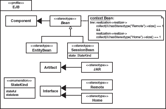
This diagram should be more or less self-explanatory after the explanations above. However, some interesting aspects should be mentioned in this context. On one hand, stereotypes can be abstract, which conceptually means the same as for abstract classes: they cannot be directly annotated to model elements; they merely serve as a basic (meta-) class for further stereotypes. Stereotypes can also inherit from each other. Constraints that are defined for stereotypes mean that these constraints must be valid for classes to which the stereotype is applied. In our example in Figure 6.14, this means that a Bean must implement exactly one RemoteInterface and one HomeInterface. Additionally, this example demonstrates how Enumerations, which are used only for typing a tagged value in this case, are modeled.
A profile is not independent. Instead it always depends on and uses a reference metamodel. This can either be the UML metamodel or an existing profile. The profile is unable to change or remove the existing definitions in the reference metamodel, but the profile mechanism is a well-defined back-door through which new constructs (stereotypes) and their properties (tagged values) can be added. The same is true for additional modeling rules (constraints) that further restrict the constructs’ interplay, and are thus able to formalize the well-formedness of models of the specific language.
This can also serve as a basis for the adaptation of UML tools, so that the developer is alerted to profile-specific modeling errors as early as during modeling. As a rule, most of the currently-available UML tools are not as advanced as this yet. In many tools, modeling rules are still supported – if at all – by proprietary mechanisms such as scripts or plug-ins. Until this changes, the following options for dealing with profiles in practice are available:
- The constraints in the profile only serve documentation purposes: if necessary, they are merely notated non-formally.
- The formalization (implementation) of profile constraints is carried out via mechanisms specific to the UML tool.
- Testing for well-formedness is left to the MDA/MDSD generator, which can validate a profiled model independently of the UML tool, should this be required. In this case, the modeling rules would have to be ‘taught’ to the generator. If an OCL interpreter is used for this purpose, it is even possible to evaluate an OMG-conformant formal profile definition.
6.6 Metamodeling and OCL
OCL is the abbreviation for Object Constraint Language. This is a side-effect-free, declarative language for the definition of constraints (restrictions) such as modeling rules for MOF-based modeling languages. Constraints enrich models with additional information about the validity of model instances. Constraints are suitable for application at the M1 as well as the M2 levels.
Let’s assume we have a UML model that contains an association between people and cars, as shown in Figure 6.15. A person can either have the role of driver or passenger. While anyone can be passengers, drivers must be at least eighteen years old and hold a driver’s license. How can we express this in UML?
Figure 6.15 A sample model to illustrate OCL.

Apart from the suboptimal option of defining a subclass of people called AdultPersonWithDriversLicense and its driver-association, the only other option is to use a constraint. In the following examples, constraints are described verbally and via OCL.
For all instances of Car it holds that drivers of a car must be at least eighteen years old (invariant).
Car
driver.age >= 18
For all instances of Company it holds that a company’s potential drivers are all those employees who are older than eighteen.
Company
potentialDrivers = employees->select( age >= 18 )
For the operation drive() of the class Car it holds it can only be called when no driver is seated in the vehicle and the person passed as the argument is older than eighteen (precondition). After the operation has been carried out, the person passed as the argument takes on the role of driver (postcondition).
Car::drive(p : Person)
pre : (driver == null) &&
    (p.age >= 18)
post: driver = p
For the operation recruit() of the class Company it holds that after the operation has been executed, the list of employees has grown by one, and the added person is now part of this list.
Company::recruit(p : Person)
pre : -- none
post: (employee.size = [email protected] + 1) &&
    (employee.includes(p))
As should be clear from these examples, constraints written in OCL are both more precise and more concise than free text. In particular, they are formally coupled with the model. OCL does have special meaning in the metamodeling context. This is because metamodels should be extremely precise and tool-processable: a constraint written in natural language can’t be processed by a verification tool.
First and foremost, OCL constraints are modeling language-independent. This especially means that OCL constraints can be used at various metalevels. The example given above uses OCL in a concrete UML model, that is, at the M1 level. Here, it affects the instances of this model’s elements: in general, a constraint in Mn affects Mn−1. OCL is particularly significant in the context of model-driven development, because it can also be used at M2, for example in the context of a metamodel extension. Figure 6.16 shows an extension of the UML metamodel with an OCL constraint.
Figure 6.16 OCL constraints at the metamodel level.

6.7 Metamodeling: Example 1
We now develop our own metamodel for demonstration purposes that has nothing to do with the UML, that is, one that doesn’t extend the UML metamodel. For our example, we are going to use the feature models known from generative programming and the FODA method ([EC00], [FODA]). This example is introduced in more detail in Section 13.5.
Figure 6.17 shows the metamodel of such feature models. Please note that this is the metamodel of the feature model. We will not discuss its graphical representation as a diagram here.
Figure 6.17 A metamodel for feature models.
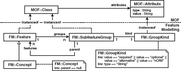
We first define a Feature as an instance of MOF::Class. A feature can have a number of subfeature groups. A SubfeatureGroup is also a MOF::Class and contains various subfeatures. A subfeature group has a kind, which can be required, optional, alternative or n-from-m, modeled using the attribute kind. Here, GroupKind gets the attributes Type and Value through inheritance from the super metaclass MOF::Attribute. Alternatively, one could have also defined SubfeatureGroup as an abstract metaclass and the various kinds as concrete subclasses.
The diagram in Figure 6.18 shows an excerpt of the example-feature model in Section 13.5.3 as a UML object diagram based on the metamodel we just defined. This diagram shows very clearly why it is important to use a suitable graphical notation, in this case that of the feature diagrams. This is much more readable and easier to create than a (theoretically adequate) UML object diagram. The acceptance of domain-specific modeling is often mainly a question of the suitable graphical notation, and of good tool support.
Figure 6.18 Feature model visualized using the concrete syntax of UML object diagrams (the affected part is shown in a feature diagram in the lower left corner).

Feature models can be enriched by further information. For example, one can determine whether a feature is considered final or whether possibly additional features may be added, if necessary in connection with a new SubfeatureGroup. In the latter case, such a feature is called open. The metamodel can easily be extended, and its rendering in an instance diagram is obvious, as Figure 6.19 indicates.
Figure 6.19 Metamodel and concrete syntax.

The use of feature models is discussed in depth in Section 13.5.3.
6.8 Metamodeling: Example 2
An extremely simplified component infrastructure [VSW02] usable for small devices and embedded systems (see Chapter 16 and [Voe02]) will serve as another example for metamodeling. A central ingredient of applications based on this infrastructure are – obviously – components. During architecture definition, it makes sense to define what a component is, which is why we start with the definition of a metamodel for components of this infrastructure8.
Figure 6.20 shows a simple example of a concrete model that uses the component concept. It shows component dependencies in a mobile phone SMS messaging application. First, we want to express the fact that a component can offer a number of services that are defined as provided ports. A provided port is associated with an interface that defines the available operations. Furthermore, a component must convey which resources it needs. This is accomplished by assigning a required port to the component. This port, too, has an interface. In this case the interface specifies which operations the component requires from other components.
Figure 6.20 An example of a simple component-based system.

In addition, a component has a number of configuration parameters. To simplify matters, these are attributes of the component class that must be of the type String, as they are read from a configuration file at system start-up.
Finally, there are special types of components that only use services and don’t offer any: applications.
The example in Figure 6.20 features an application SMSApp that defines three required ports. These are linked to interfaces that define the respective other ports. For example, the service interface of the TextEditor component is needed for the user to input an SMS. The TextEditor as well as the MenuUtilities need the UIManager to be able to access the screen. Figure 6.21 shows the metamodel of this architecture.
Figure 6.21 Metamodel for the description of components.

This metamodel formally expresses what we described above in words, at least in part. The coupling of an instance diagram (the SMS application shown in Figure 6.20) with the metamodel is accomplished via stereotypes and graphical notations: the ports are – following UML 2.0 – modeled as small rectangles on the component’s edge. Attributes of such components are by definition configuration parameters. As components, applications are assigned the stereotype «Application». To avoid having to create a completely new metamodel from scratch, the UML metamodel will serve as a basis for our own. We remember the statement ‘A configuration parameter is an attribute of type String’. In slightly different words: the metaclass Attribute occurs in the UML metamodel. It has an attribute named Type. We are merely saying that the metaclass ConfigParam is a subclass of Attribute, whose attribute Type must have the value String. The diagram in Figure 6.22 illustrates this, as well as the other consequences of basing our metamodel on the UML metamodel. Note the use of OCL for defining the necessary constraints.
Figure 6.22 Component metamodel connected to the UML metamodel.

We can now proceed analogously for the other elements of our metamodel. Figure 6.22 shows the result, while we introduce the namespace, respectively the package CM (for Component Model).
What is the actual benefit of this explicit metamodeling? As always, modeling only makes real sense if the models don’t end up collecting dust in a drawer: they must be usable in software development, true to the MDSD principle. This applies to metamodels too, of course. These should be implementable and support the further development process. Therefore, it is important not to just ‘draw’ a metamodel in the form of a diagram, but to adapt the development tools using the metamodel too.
Effective, domain-specific modeling can only work if a suitable modeling language is available for the domain to be modeled and this language is ‘understood’ by the development tools. The aspects listed at the beginning of this chapter – model validation, transformation, code generation and tool adaptation – are relevant here.
We next take a closer look at the first of these aspects, model validation. The remainder are illustrated in the case study in Chapter 16, which expands the component example featured above.
6.9 Tool-supported Model Validation
Tool support for metamodeling varies widely. It is possible to distinguish between the following alternatives:
- No support. Most UML modeling tools offer hardly any support for metamodels. This is not meant as negative criticism – they are simply not made for this purpose. They are implicitly based on the UML metamodel, which is unchangeable. Of course, this leaves the option of coupling a model to a metamodel via a stereotype, yet no further support (or validation) is provided. Practically all widely-used UML tools fall in this category. However, there is a slow yet noticeable tendency toward growing support for UML profiles.
- Separate tools. Some tools are applied after a model has been created with a normal UML tool. Typically, the model is exported from the UML tool using XMI (XMI is an XML mapping for MOF, see Chapter 12) and further processed on this basis. Such tools include model validators, transformers, and code generators – almost anything that covers the full range of these tasks, often not limited to UML/MOF – and can even handle any modeling language. One example of this category is the Open Source generator openArchitectureWare described in Chapter 3.
- Integrated (meta-)modeling tools. Other than normal UML modeling tools, integrated (meta-)modeling tools are actually internally based on a metamodel. With the help of the tool, the user can not only adapt the metamodel, but can also create new models based on this metamodel. The tool will then adapt its interface and ensure that only valid models can be created. In most cases, validation takes place in real-time, that is, during input. Examples of such tools are MetaEdit+ [MC04] or [GME].
Most common is a combination of a UML tool and a separate generator/validation tool. Unfortunately, integrated metamodeling tools are still largely ignored by the market.
Let’s now look at model validation via openArchitectureWare. Its functional principle is illuminated in Figure 6.23.
Figure 6.23 Functional principle of the openArchitectureWare generator.

The generator uses any model as its input data. This is parsed by the parser, and the resulting parse tree is then instantiated by the metamodel instantiator using the configured metamodel. The input (model) format is interchangeable, because different parsers can be used in the generator. In our example, XMI is used, as in many cases. After instantiation of the metamodel, the model is available as an object graph of Java objects in the generator’s memory. The object’s Java classes correspond to the metaclasses of the metamodel. The actual code generation via templates can now take place, as we explained in our first case study in Chapter 3. We said above that metamodeling is, after all, a means for defining the ‘language’ available to the modeler. This especially includes the definition of modeling rules and the respective validation of concrete models.
Let’s return to our component example above. The generator we use possesses an explicit, configurable metamodel. This is implemented in Java. The principle has been explained in detail in Section 3.2. Thus it should be clear what a metamodel adaptation looks like: we create a subclass of the corresponding metaclass and configure in the generator that instances of the new metaclass are mapped to the newly-implemented metaclass in the model. Here the example for ConfigParam:
package cm;
public class ConfigParam extends Attribute {
}
Using a configuration file (not shown here), we tell the generator that all UML attributes with the stereotype «ConfigParam» are actually configuration parameters, which is why it should instantiate the subclass ConfigParam instead of Attributes. From the generator’s perspective, this is not a problem, because as always in OO programming, an instance of a subclass can be used if a variable is typed with the superclass – polymorphism.
So far this class ConfigParam is not of much use to us, especially since we haven’t contributed much to model validation at this point. ConfigParam is for example missing the constraint that the type of a ConfigParam always has to be String. To check such constraints, all metaclasses possess an operation CheckConstraints that is called by the generator once the entire metamodel has been instantiated. This is the primary place where model validation takes place. If this operation detects a problem it throws a DesignError that is then reported to the developer, indicating that the processed model is not consistent with the metamodel. This is the code for CheckConstraints of the class ConfigParam9:
public String CheckConstraints()
        throws DesignError {
    if ( !Type().Name().toString().equals(“String”) ) {
    throw new DesignError(
        “ConfigParam Type not String” );
    }
      return super.CheckConstraints();
}
To gain a better understanding of what is happening here, it is helpful to look at the UML metamodel used by the generator and extended by ConfigParam, as shown in Figure 6.24.
Figure 6.24 ConfigParam excerpt from the metamodel.

Since we are operating in the context of the class ConfigParam, the expression Type () provides the instance of the UML::Type object by following the inherited Type association of the class Attribute. The type has an attribute Name of the type String, which contains the name of the type. Note that the implementation of the constraint does not happen declaratively with OCL, but operationally via Java. The integration of an OCL/Java compiler is possible here, and will certainly happen in the near future in the context of the openArchitectureWare Open Source project.
In the same manner, we now proceed to create metaclasses for Component, ProvidedPort and RequiredPort. A few examples follow.
The metaclass for Component can e.g. look something like this:
public class Component extends Class {
    public ElementSet Port() {
      // return all ports of the component
    }
    public ElementSet RequiredPort() {
      return Util.filter( Port(), RequiredPort.class );
    }
    public ElementSet ProvidedPort() {
      return Util.filter( Port(), ProvidedPort.class );
    }
    public void CheckConstraints() {
      Util.assert( Operation().size() == 0,
       “Component must not define operations by itself” );
    }
}
The helper function Util.filter() filters a number of objects (here, the ports) for a specific metaclass. For example, the operation ProvidedPort() returns all ports that are actually provided ports. Note also the operation CheckConstraints(), which can be used for implementing invariants of the metamodel.
We can now look at the metaclass Application. This is a special kind of component that is not allowed to have ProvidedPorts.
public class Application extends Component {
  public void CheckConstraints() {
    Util.assert( ProvidedPort().size() == 0,
      “Application must not have any provided”+
      “ports, only required ports are allowed.” );
  }
}
Here, too, CheckContraints() is used to guarantee that an application has no provided ports.
6.10 Metamodeling and Behavior
Behavior in the context of metamodeling is interesting in two respects. On one hand behavior can be hidden in the metamodel’s meaning, while on the other one can use metamodeling to make behavior modeling explicitly accessible, for example in the form of activity or state diagrams.
Here, we will focus on the former scenario. We’ll illustrate this using the familiar component example: let us assume we require each component to have an operation init(). This is realized most easily if we define an interface that contains this operation and that also require that all instances of the metaclass Component must implement the interface.
A simple calculator serves as an example, as is shown in Figure 6.25.
Figure 6.25 An example of ‘All components must implement a specific interface’.

The question is, what happens in the init() operation? For example, one can check whether links are available for all RequiredPorts. These links10 are created by the Container. For this purpose, the component implementation offers a corresponding set operation for each RequiredPort, which is called by the container. The implementation of these operations saves the reference to the component that provides the ProvidedPort for the respective RequiredPort in an attribute. When init() is called by the container, the component instance expects these links to be present, that is, the corresponding attributes must no longer be null. The algorithm to verify this is as follows:
foreach r:RequiredPort {
  if (Attribute with the name of the port == null ) {
    ERROR!
  }
}
This is a form of behavior that is not programmed by the user, but is instead implicitly determined by the architecture’s guidelines. This has the following effects:
- The programmer who creates an application doesn’t have to deal with it.
- In this case, the model validation is limited to making sure that each component implements the LifecycleInterface. This happens as explained above. The behavior within the method is not validated because the implementation code (see below) can be generated automatically.
- If desired one can also specify this behavior at the metamodel level, for example via sequence diagrams, action semantics (see Chapter 12), or – in this case – also using a constraint that states that all resource attributes must not be null once the operations have been executed.
- In the course of code generation, the implementation code for such operations can be generated directly. All information required for generation is present at generation time. The following section gives an example of the procedural realization of the constraint described above:
«DEFINE InitOperation FOR Component»
  public void init() throws IllegalConfiguration {
  «FOREACH Operation o IN RessourceInterface»
   if ( «o.NameWithoutSet» == null ) {
    throw ( new IllegalConfiguration(
      “Resource «o.NameWithoutSet» not set!” ) );
   }
  «ENDFOREACH»
«ENDDEFINE»
By the way, it is noteworthy that large parts of application’s behavior are often really behavior that is defined by the architecture. Among these are persistence, workflow, or remote proxys. All these aspects can easily be generated completely. For more details on modeling behavior in DSLs, see Section 8.1.3.
6.11 A More Complex Example
This section contains a more complex example of metamodeling. We are dealing with a part of the ALMA telescope here11. ALMA [ALMA] is an international astronomy project that pursues the goal of building an array of fifty radio antennas in the Atacama Desert in Chile. Several international organizations participate in this project: ESO, IRAM, MPI, NRAO. The fifty antennas are all connected to form a radio interferometer to achieve much higher resolution than is possible with a single antenna. To vary the telescope’s resolution, the positions of all fifty antennas can be physically changed using fork lift trucks.
Naturally, such a project requires a fairly elaborate software infrastructure. This consists of:
- Real-time parts for controlling the antennas, implemented in C++ and CORBA.
- Job definition scripts, implemented in Python.
- High-performance calculation modules for correlation and post-processing of digital images, implemented in C++.
- A ‘classic’ IT infrastructure, implemented in Java, for definition of the projects, data management, and remote access to the telescope infrastructure – the telescope is located at a height of 5,000 meters in Chile, while the scientists do their work remotely over the Web.
Many of the system’s data structures are needed by several of these subsystems. Due to the many non-functional requirements, the data structures must be available in different representations: XML for storage and remote transport, CORBA structures in the telescope control system, as well as some astronomy-specific formats for more efficient processing of raw data.
It was therefore decided to define the data structures with UML and to generate the various other artifacts from that12:
- XML schemas
- Wrapper classes for XML as well as (de-)marshalers in various languages (C++, Java, Python)
- Converters for the proprietary data formats
- HTML documentation for the data model
6.11.1 The Basics
We must first differentiate between Entities and DependentObjects. Entities have their own ID and can be searched based on several properties. An Entity can be subdivided. Its parts are DependentObjects. These do not have an identity of their own and cannot be searched – only the possessing entity knows them and references them. Parts can contain further parts. Figure 6.26 shows two examples:
Figure 6.26 An example of Entities and DependentObjects.
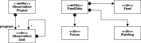
An ObservationProject contains multiple ObservationUnits. These form a tree whose root is referenced with program by the ObservationProject. In the other example, observation data is shown. Without going into too much detail here, one can see that the FeedData consists of various substructures.
After coupling the metamodel to UML (that is, extending the UML metamodel), the metamodel for such models looks like Figure 6.27:
Figure 6.27 Metamodel for Entities and DependentClasses, coupled with the UML metamodel.

6.11.2 Value Types
Other distinctions of the data exist in the data model. Specific information, such as a star’s position in the sky, are neither DependentObjects nor are they primitive types. For this reason, we introduce ValueTypes. ValueTypes have no identity: they consist of only their value. Two ValueType instances of the same value are considered identical. As a convention, it is defined that the attributes of Entities or DependentObjects can only be primitive types or ValueTypes. The reason for this is that these values occur repeatedly all over the system. An example for the use of ValueTypes is shown in Figure 6.28:
Figure 6.28 An example of the modeling and usage of ValueTypes.

The metamodel is expanded accordingly. Since Entities as well as DependentObjects and ValueTypes have the same restrictions on their attributes, a corresponding abstract metaclass AlmaAbstractClass is introduced. This is common practice in object-oriented programming and is used here at the metalevel, as Figure 6.29 shows.
Figure 6.29 Metamodel with AlmaAbstractClass factored out.

In this case we agreed to write the constraints in natural language rather than in OCL, because the generator requires manual programming of the constraints in Java anyway. The constraint for the attribute types could be described as an OCL constraint as follows:
context AlmaAbstractClass
inv: attribute->forAll( a |
        (a.oclIsKindOf(ValueType) ||
    a.oclIsKindOf(PrimitiveType) ) )
6.11.3 Physical Quantities
Since ALMA is, after all, a physical measurement instrument, the data it works with involves lots of physical quantities. It therefore makes sense to provide physical quantities explicitly as such in the metamodel. Physical quantities possess both a value and a unit, such as ‘10 arcsec’ – 10 is the value, arcsec the unit. Various quantities have certain well-defined units and value ranges. For example, angles have the units degree or arcsec (arcsecond). Distances are measured in mm, cm, km, and pc (parsecs). All these aspects have to be reflected in the model. There are different options for visualizing this information in the model – we decided to use the one shown in Figure 6.30. Again, angle and distance serve as examples here.
Figure 6.30 Definition and use of physical quantities.
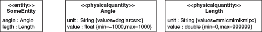
The units are laid down in an attribute unit, which must be of type String. The value must be of type int, long, float. or double. The list of valid values for the unit attribute is given via tagged values: we use a list divided by ‘|’. Physical quantities can be used like ValueTypes, so they must also appear as attributes of an AlmaAbstractClass.
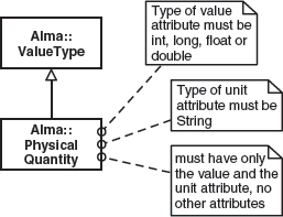
We next want to develop the respective metamodel. First, PhysicalQuantity is a subclass of ValueType (this should be clear after the discussion above) – PhysicalQuantities are a special kind of ValueType. Look at Figure 6.31 for the metamodel – for reasons of simplicity, we have again formulated the constraints in plain English.
Figure 6.31 Metamodel for physical quantities.
BoundedAttribute (see Figure 6.32) must be of the type int, long, float, or double. Two attributes min and max are also defined. These attributes of the metaclass appear in the model as tagged values, and are actually characteristics of the physical quantity defined in the model. The minimum and the maximum value are of the same type as the attribute itself. EnumAttribute can have any type. The tagged value values defines the valid values of the type to be defined.
Figure 6.32 Special kinds of attributes.

However, the correlation between the physical quantity and the two new metatypes is still missing. Figure 6.33 shows this.
Figure 6.33 Excerpt from the complete ALMA metamodel.

6.12 Pitfalls in Metamodeling
This section presents a few tips and tricks and reveals some of the pitfalls in metamodeling that particularly concern UML:
- One often reaches a point in metamodeling where it is no longer obvious which notation must be used.
- Accidentally finding oneself on the wrong metalevel.
In general, asking the central question of how the metamodel could be implemented in a programming language can prove useful. This view can, if reversed, give us hints for revealing which notation is the correct one.
6.12.1 Interfaces
Problem: You wish to express the fact that instances of a metaclass Entity (that is, all Entities) must implement a certain interface.
Correct solution: The set of implemented interfaces of an Entity must contain SomeInterface. This can either be expressed via an OCL constraint, or by subsetting the respective meta-association (see Figure 6.34).
Figure 6.34 All Entities must implement a certain interface (correct).
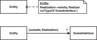
Incorrect solution: Figure 6.35 shows that the metaclass Entity implements the interface SomeInterface. This is not the same statement as the original one.
Figure 6.35 All Entities must implement a certain interface (incorrect).

Sometimes, the latter is required for other reasons. Assume there is a number of metamodel elements whose instances must all have names. It will possibly make sense to define an interface on the metalevel that contains the operation getName(). Figure 6.36 shows this.
Figure 6.36 Use of interfaces and the Implements relationship at the metamodel level.

6.12.2 Dependencies
Problem: You want to express the fact that components can depend on interfaces because they invoke their operations.
Correct solution: You define an association between component and interface and call it uses. Figure 6.37 demonstrates that a component can use many interfaces and that an interface can be used by many components.
Figure 6.37 Dependencies (correct).

Incorrect solution: The model in Figure 6.38 states that the metaclass Component somehow depends on the metaclass Interface.
Figure 6.38 Mappings (incorrect).

Note that a Dependency like the one in Figure 6.38 can never have cardinalities. The statement ‘depends on several interfaces’ cannot therefore be expressed.
6.12.3 IDs
Problem: Entities must have exactly one attribute with the name ID of type String. This represents the identifying attribute or the primary key. We proceed on the premise that the metaclass Entity inherits from UML::Class and thus possesses the inherited association Attribute, which defines the attributes of the class.
Correct solution: The correct solution in Figure 6.39 uses an OCL constraint that states that among the attributes of the entities there must be one with the name ID and the type String.
Figure 6.39 Entities must have exactly one attribute with the name ID of the type String (correct).

Incorrect solution: The definition of an Entity attribute of the name ID, as shown in Figure 6.40, does not yield the correct result. Instead, it represents a definition of a tagged value for the metaclass Entity.
Figure 6.40 Entities must have exactly one attribute with the name ID of the type String (incorrect).

By the way, the following constraint in the correct model would also be incorrect:
context Entity inv:
Attribute-~select(
        (Name = “ID”) && (Type.Name = “String”)
    )-~size = 1
This constraint would permit the existence of various attributes of the name ID, but only one of the type String.
6.12.4 Primary Keys
Problem: All instances of Entity must have among their attributes exactly one of the type EntityPK. Here, EntityPK is a specialization of the metaclass Attribute.
Correct solution: Figure 6.41 shows the correct metamodel:
Figure 6.41 All instances of Entity must have among their attributes exactly one attribute of the type EntityPK (correct).

Incorrect solution: Figure 6.42 displays the same problem that we dealt with in the Section 6.12.3, the definition of a tagged value.
Figure 6.42 All instances of Entity must have among their attributes exactly one attribute of the type EntityPK (incorrect).

6.12.5 Metalevels and Instanceof
This example illustrates one of the pitfalls in the use of complex modeling languages using UML an example.
Figure 6.43 shows a UML class diagram (M1) and a UML object diagram (M0). Objects are instances of classes that are defined in the class diagram. So far, the object-class relationship is very clearly an instanceof relation, of which the fact that more than one object of the same class can exist is further proof. The same is true for the relationship between link and association.
Figure 6.43 Objects as instances of classes.

As can be seen in Figure 6.43, objects and classes are located on different metalevels. On the other hand, they are on the same metalevel in terms of UML. Classes as well as object models are instances of UML metamodel elements. Figure 6.44 shows this:
Figure 6.44 Model elements as instances of metamodel elements.

On closer inspection, this apparent contradiction is easily resolved: the two instanceofs are not the same language construct. In the first example, instanceof is part of UML and is defined in that context (see Figure 6.45).
Figure 6.45 The instanceof relation defined in UML.

The relation between UML::Class and UML::Object is an MOF::Association. It defines the instanceof relation between instances of UML::Class and UML::Object in instances of this (meta-)model – that is, in UML models. Nevertheless, all model elements (me, my father, myVS-bus, myfathersGolf) are of course instances of UML metaclasses, in this case UML::Class or UML::Object.
1 What has been said so far is not only true for models/modeling languages, but analogously also for programming/ programming languages.
2 Since we use UML as the M1 language, M2 must be the UML metamodel.
3 Levels 0–3 have fixed names only in the context of the OMG.
4 Strictly speaking, tagged values are no longer tagged values, but the representation of the stereotypes’ attributes. Since they still look like tagged values, though, they are still termed tagged values.
5 UML 2.0 formally defines this a little differently – see below.
6 In the interest of brevity, some constraints are left out.
7 The OCL that is used for the constraints in this model are explained later.
8 Since we map the concepts of the target architecture in the metamodel, this is an example of architecture- centric, model-driven development.
9 In this example, Type and Name are attributes of the metaclass Attributes. Unfortunately in this case the generator uses attributes spelled with capitals at the beginning of a word, which is a little confusing, but outside our control.
10 Links are instances of associations.
11 We thank the European Southern Observatory (ESO) for their kind permission to let us use this example here.
12 For any astronomers amongst our readers: of course, the example is somewhat simplified.