Chapter 15
Creating Stairs and Railings
Creating stairs and railings in Autodesk® Revit® Architecture software can be challenging. In addition, stairs and railings are often sculptural as well as functional, and there’s a limit to the amount of customization you can design with the provided tools and commands.
An entire book can be written about mastering stairs and railings in Revit, considering the breadth of functionality in these tools and the unlimited number of design configurations they can be used to create. Instead of walking through a few examples of creating stairs and railings, this chapter will give you foundational knowledge about the rules, parts, and key functionality of these tools so that you can use them in the most effective way possible for your own designs. We will also give you some ideas to tackle tougher design challenges by thinking beyond the default tools.
In this chapter, you’ll learn to:
- Understand the key components of stairs and railings
- Understand the different stair tools and apply them to custom designs
- Design railings and use the Railing tool for other model elements
- Implement best practices
Designing Stairs and Railings
Designing and iterating complex stairs and railings in any software application can be difficult. You will need to thoroughly understand the rules and constraints of the application—in effect, learn the language of the application. To communicate fluently in that language, you need to be able to think fluently. You almost have to be able to think beyond the individual words and begin to arrange whole ideas.
Regardless of how well you know how to use a particular application, you have to incorporate imagination and complex design issues. Sometimes stairs and railings are straightforward and functional (for example, a steel or concrete egress stair), and there’s not much room for creative thinking. But in many cases, stairs and railings are conceived as feature elements within a space. They’ll be touched and experienced up close. They may be extraordinarily complex and spatial—almost an inhabited sculpture (Figure 15.1).

Figure 15.1 Detail of the feature stair in Apple’s Fifth Avenue retail store
Source: Image courtesy of Dougal McKinley
Revit is purpose-built for designing building elements and relating them to the rules of commonly constructed relationships (doors associate with walls, furniture associates with floors, and so on). The software is biased toward relationships specific to designing a building and maintaining those relationships as the design changes. To make things a bit more complicated, there’s a specific language for creating stairs and railings in Revit Architecture. For example, Figure 15.2 illustrates the Edit Baluster Placement dialog box for a baluster condition.

Figure 15.2 Edit Baluster Placement dialog box
Before we begin detailed exercises for creating stairs and railings, let’s review the main components of each object type and how they are organized within Revit.
Reviewing the Key Components of Stairs and Railings
Stairs and railings are system families, so they exist only within the project environment. As you should already know, these types of families can be shared between projects only by copying and pasting, using the Transfer Project Standards tool, or including them in your project templates. There are several component family templates that serve as subsets of stair and railing system families, such as profiles, posts, and panels.
Reviewing the Basic Rules of Stairs
Before you start to create any stairs in a project, you should become familiar with the basic rules related to these special elements in Revit Architecture. We will discuss the actual geometric components later, but first let’s review the parameters that drive the geometry. When you launch the Stair tool, it is assumed that you want a stair to be generated between two levels. If you start the tool from a floor plan view, the base level will be the level associated with the floor plan view and the top will be the next level above. Keep in mind that this may be a level that is not the next major level above; it could be a minor level such as a mezzanine. Always check the instance parameters in the Properties palette when you are creating a new stair (Figure 15.3). You can also assign top- and base-level offsets in the instance parameters the same way you can for walls.

Figure 15.3 Instance parameters for a stair
Using the overall height determined by the base and top levels, the stair object will be equally divided into risers. The maximum riser height is defined in the type properties of every stair type. The overall height of the desired stair will be equally divided into risers not exceeding the defined maximum riser height. Tread depth is specified in the stair’s type properties as well, but that may be overridden if you manually lay out the treads in Sketch mode.
In addition to the simple rule of overall riser height, some public agencies require a stair calculation to be employed for dimensional compliance. This type of calculation can be enabled from the stair’s type properties as well. With either of the stair commands activated, click the Edit Type button and then the Edit button in the Calculation Rules parameter. This will give you the Stair Calculator dialog box (Figure 15.4), which will allow you to enter the code-based values driving the creation of new stairs.

Figure 15.4 The Stair Calculator dialog box
Whether you use Stair By Component or Stair By Sketch, the stairs you create will be associated with a base level and top level. You can also assign offset distances to the base and top levels, which allow the stairs to start or end later or sooner depending on the design. Because the stairs remain associated with these datum objects, if the datum objects are adjusted or the offsets are redefined, the stairs will automatically adjust within the calculated rules. This means that if the height reduces, the riser count will remain but each riser will be shorter. In other words, the footprint or plan of the stair will remain unchanged. If the height of a stair run increases and an automatic adjustment would violate the maximum riser height, you will receive a warning that the actual number of risers is different from the desired number of risers. In other words, the footprint of the stair will not change automatically. It is up to you to edit the stair to add more risers where you feel they are appropriate.
Before we discuss the basic component of stairs and railings, download and open the file c15-00-Stair-Rail.rvt or c15-00-Stair-Rail-Metric.rvt from this book’s web page at www.sybex.com/go/masteringrevitarch2016.
Working with Stair Components
Using either the Stair By Sketch or Stair By Component tool, the basic elements of a stair are similar. The main part of the stairs—the risers and treads—is called the run in Revit. The structural elements that hold the run in place are known as stringers in the Stair By Sketch tool, and they are called supports in the Stair By Component tool. Finally, landings are addressed as unique elements in the Stair By Component tool. In the Stair By Component tool, each of these three basic elements (run, support, landing) is defined with its own unique type properties. When you use Stair By Sketch, they are all defined in the properties of each stair type.
Run The critical parts of a run are the construction, material definitions, and tread and riser settings. There are two system families for runs in the default project template: Monolithic Run and Non-Monolithic Run. A monolithic run is essentially a single material for the stair, stringer, tread, and riser. Typically, monolithic runs are used for cast-in-place and precast concrete stairs, whereas non-monolithic runs are for stairs made of wood, metal, and various other materials.
Support The supports for an assembled stair usually take one of two forms. In Revit, these are referred to as carriage (open) or stringer (closed), as shown in Figure 15.5. Carriage and Stringer are system families you can find in the Project Browser under Families ➢ Stairs. After you select either the Carriage or Stringer option in the stair type properties, you can select one of the respective support types. For example, the Right Support property may be Carriage (open) and the Right Support Type value would be Carriage – 2" Width. You cannot customize a stringer or carriage profile when you use the Stair By Sketch tool.

Figure 15.5 Stair support options
Landing Landings are the transitional elements between runs. As such, one of the main settings in the type properties for a landing is Same As Run. With this setting enabled, you are left with only the identity data and the material property for monolithic landings. If the Same As Run setting is disabled, you can treat the landing as another tread with the same opportunities to apply a thickness and a nosing profile.
 Reviewing the Components of Railings
The major parts of a railing are the profiles, different kinds of balusters, and the nested types within each railing family. Additional functionality is available to help integrate different railing parts into a more cohesive system. In Figure 15.6, a common railing is shown to illustrate the fundamental parts of a railing type.

Figure 15.6 The integrated parts of a railing type
Let’s examine some of these railing components in greater depth:
Profiles The profile is the most basic component used to model a railing. All the rails, posts, and balusters are generated from profile families. You can have as many profiles per railing as you like, but you can’t have more than one shape in a profile family (RFA) file. In each profile family, the shape needs to be a closed loop—no gaps or overlapping lines allowed. Furthermore, all the railing profiles will be swept parallel to their host objects. In Figure 15.7, the top rail and all the intermediate rails are simple circular profiles swept along the path of the railing.

Figure 15.7 Multiple profiles per railing
Balusters There are three kinds of baluster family templates you can use to customize a railing type:
- Baluster posts have built-in instance parameters to control the height of the baluster so that it can adjust automatically when used within a railing type in a project. The posts are used at the start, end, and transitions of railings.
- Balusters are the main, repeated vertical structure of most railing designs. They have instance parameters as well that control the vertical length and the angle of the top and bottom of the baluster (Figure 15.8). When you create your own custom baluster families, you must constrain the geometry to these reference planes so the baluster will adapt to the settings in the railing type.
- Baluster panels have controls much like the baluster, but there are additional reference planes to control the overall width of a desired panel (Figure 15.9).

Figure 15.8 A baluster template

Figure 15.9 A baluster panel template
Top Rail The top rail is a separate component of a railing type. That is to say, it will not appear in the Edit Rails dialog box. Instead, you will find the Top Rail settings in the type properties of the railing and they consist only of a height and a type. The top rail is a nested system family that you can find in the Project Browser under Families ➢ Railings ➢ Top Rail Type. Locate and double-click Circular – 1 1/2" (Circular – 40 mm). You will find more detailed settings to control this subset of railing functionality (Figure 15.10). Let’s take a look at some of the properties of a top rail: Construction, Terminations, and Extensions.

Figure 15.10 Top rail type properties
Construction The first category of properties in a top rail defines the basic construction of the rail. Here you will select a profile and specify other behavior such as default join condition, transitions, and hand clearance.
Terminations Another top rail option is defining a termination. This is a family component that can be used at the end of a rail or rail extension. There is only one termination family loaded in the default project template, but you can create your own family using the
Railing Termination.rftorMetric Railing Termination.rftfamily template. Figure 15.11 shows an example of a termination.

Figure 15.11 Rail termination
Extensions When you need a rail to extend beyond its main sketch definition of the railing, an extension can be specified as part of the rail type. The extension is an integrated part of the rail, so it’s controlled by the same properties like size or materiality. In the settings for Extension (Beginning/Bottom), you can select an option called Plus Tread Depth. This is to accommodate common building codes that require a stair handrail to be extended the length of one tread plus some standard distance. Extension Style is a setting that gives you three predefined designs for the rail extension: Wall, Floor, or Post (Figure 15.12).

Figure 15.12 Options for rail extension styles
You can customize a rail’s extension by pressing the Tab key to select the rail. Then click Edit Rail in the contextual tab in the ribbon, and click Edit Path.
Handrail The handrail is another system family that is nested within a railing family, and its properties are almost identical to those of the top rail family. The one exception is that handrails can use support families. From the Project Browser, navigate to Families ➢ Railings ➢ Handrail Type and then double-click Circular – 1 ½" (or Pipe – Wall Mount in the metric equivalent) to open the Type Properties dialog box for a handrail (Figure 15.13).

Figure 15.13 Type properties for handrail supports
Beyond selecting a support family, you will notice settings for Layout that include Align With Posts, Fixed Number, Fixed Distance, Maximum Spacing, and Minimum Spacing. These are the main controls that will enable or disable the other settings for Supports, including Spacing, Justification, and Number.
Rail Structure (Non-Continuous) Let’s return to the type properties of the main railing family. In the Project Browser, navigate to Families ➢ Railings ➢ Railing and double-click Guardrail – Pipe (900 mm Pipe in the metric exercise file). In the Rail Structure (Non-Continuous) parameter, click the Edit button to open the Edit Rails (Non-Continuous) dialog box (Figure 15.14). In this interface, you can insert rails defined by profile families as well as set their relative height, horizontal offset distance, and material. These rails are considered non-continuous because they will be intersected by any balusters you define in the Baluster Placement settings. Click OK to exit this dialog box.

Figure 15.14 The Edit Rails (Non-Continuous) dialog box
Baluster Placement When you return to the type properties of the railing, locate the Baluster Placement parameter and click the Edit button to open the Edit Baluster Placement dialog box (Figure 15.15). As you can see, there are options for the main pattern and the posts and an option for how the balusters will be used on stairs.

Figure 15.15 Edit Baluster Placement dialog box for the Guardrail – Pipe family
The Main Pattern section of the dialog box is where you would assemble all your baluster types and then space and host them accordingly. You can also decide how you want the pattern to repeat (or not repeat) itself at the ends of sketched line segments. The Posts section is used to specify which baluster is used at start, corner, and end conditions (and the frequency of corner posts). Click OK to close both open dialog boxes.
That’s a high-level overview of the properties of railings and what they’re used for. We’ve covered the primary features necessary to create great railings.
Creating Stairs
Various common configurations of stairs can be created using the tools provided in Revit. Designs that used to require an outside-the-box (workaround) approach are now possible. Examples include three-run stairs (when the stair run turns back onto itself, creating an overlapping condition) and stringers with custom profiles. Despite the improvements to the stair tools, there’s still no way to anticipate every unique and sculptural design condition. In these cases, we’ll show you techniques that aren’t exactly using the stair tools as intended, but the results will geometrically resemble stairs (and their railings).
Understanding the Stair Tools
There are two different tools for creating stairs in a project environment—Stair By Component and Stair By Sketch. Each of these tools uses the core stair parts (runs, supports, landings) in slightly different ways.

When you choose the Stair By Sketch tool, you are using 2D sketch lines that represent boundaries and risers. Although you have access to a Run function in Sketch mode, it is merely automating the generation of the 2D sketch. You do not have direct access to manipulate the 3D geometry of the stair when you use Stair By Sketch. In addition, the entire stair element is bound to the rules and settings in the stair type—you cannot customize individual parts.
If you choose to use the Stair By Component tool, you have the ability to customize runs and landings within the overall stair element. You also have the unique ability to edit the stair in a 3D view. That is to say, the stair remains visible as a complete model when you edit the stair (Figure 15.16) compared to a Stair By Sketch, which collapses down to the 2D layout lines when edited.

Figure 15.16 Editing a Stair By Component in a 3D view
There are additional subcategories of the Stairs object style that allow you to further customize the appearance of stairs and their related elements (Figure 15.17). One of the subcategories is Riser Lines—providing an additional dashed line parallel to the edge of the riser that indicates the nosing length. You can customize the appearance of these elements in Object Styles from the Manage tab in the ribbon. You can also adjust the visibility of the stair elements for any view in the Visibility/Graphic Overrides dialog box and optionally save the settings to view templates.

Figure 15.17 Additional subcategories are available for stairs.
The fundamental concept behind the Stair By Component tool is that the major components of a stair (run, landing, support) are nested system families that can be independently customized. Although both stair tools are being maintained in the software, understanding the difference between all the families and types can be a challenge.
Let’s take a look at the Project Browser under Families ➢ Stairs in the default project template. The family called Stair is the parent system family for the Stair By Sketch tool. If you expand Stair, you will see the stair types that will be available to you if you launch the Stair By Sketch tool.
For the Stair By Component tool, there are three system families that function as the parent families. The following families are the top-level families into which other families are nested:
- Assembled Stair
- Cast-In-Place Stair
- Precast Stair
Under each of these families is where you define a type to be used in your projects. For example, under the Cast-In-Place Stair family, you will find the Monolithic Stair type, which uses nested families for the run, landing, and support. To better understand this nesting, let’s look at the family hierarchy of the Monolithic Stair type in a simple list:
- Family: Cast-In-Place Stair
- Type: Monolithic Stair
- Run Type: ¾" Nosing (20 mm)
- Landing Type: 7" Thickness (300 mm)
- Support Type: None
- Type: Monolithic Stair
In the Project Browser, you will find listings for the following nested families under the Stairs category:
- Carriage
- Monolithic Landing
- Monolithic Run
- Non-Monolithic Landing
- Non-Monolithic Run
- Stair Cut Mark
- Stringer
Let’s explore the ability to directly manipulate component stairs. To begin, create a stair with a landing using the Stair By Component tool:
- From the Architecture tab, on the Circulation panel, choose Stair ➢ Stair By Component. This will bring you into Sketch mode. Draw the stair from left to right. Base the base of the stair on the left of the screen, and drag your mouse to the right until you place nine risers. Click to locate the ninth riser.
- Now, move your mouse about 4' (1.2 m) to the right and click again. This will create a landing and the base for the tenth step.
-
Drag your mouse to the right, placing the other nine risers. Your stair in sketch mode should look like Figure 15.18.
Selecting the runs or the landing will display grips and temporary dimensions that can be used to change the width, direction, and location of the runs or landing.
- Widen the left run and landing by selecting the portion of the stair and pulling the blue arrow grips down, as shown in Figure 15.19.

- Now select the landing and move the lower grip to further widen the landing, as shown in Figure 15.20. The landing maintains the connection to the lower run.

- Changing the shape of the landing is not possible without converting the landing to a sketch-based component. Select the landing and then select Convert from the Tools panel. This will convert the component element to a sketch-based element. Keep in mind that this is irreversible (Figure 15.21).
- With the landing now sketch-based, you can edit its shape and create a form that isn’t rectilinear. Select Edit Sketch from the Tools panel. Delete the lower sketch line and then replace it with an arch-shaped boundary, as shown in Figure 15.22. Finish the sketch for the landing, and then click Finish Edit Mode for the component stair.

Figure 15.18 Creating the component stair with landing

Figure 15.19 Widening the left run

Figure 15.20 Extending the landing

Figure 15.21 Converting the landing to a sketch-based component

Figure 15.22 Sketching the new landing boundary
The resulting stair is shown in Figure 15.23. Don’t be afraid to experiment with using both component and sketch-based stair tools in a single stair condition. Just remember that it’s often easier to start with the component stair and then modify with sketches when necessary. This is a very powerful, flexible combination and gives you important feedback in 3D rather than going back and forth between sketches and the finished stair. This file can be downloaded from the Chapter 15 folder on the book’s web page. Look for the c15-Stair-Landing.rvt or c15-Stair-Landing-Metric.rvt file.

Figure 15.23 Combination component and sketch-based stair
USING THE INSTANCE PROPERTIES OF STAIR COMPONENTS
We have discussed the hierarchy of nested families and types for components in other chapters; stairs follow this same structure. You can Tab+select through the stair to choose either the stair or the rail, but you have other options as well. By hovering over the side of the stair, you can choose just the treads or just the stringer. Both of these selection options come with their own properties, but there are even more parameters available as instance properties of runs, landings, and supports. When you use the Stair By Sketch tool, the Width parameter is available as a simple instance parameter, accessible in the Properties palette when you are sketching the stair or afterward when a stair is selected. When the Stair By Component tool is activated, you can set the width of a run only after it has been created. If you Tab+select the run within a stair assembly, you can access the Actual Run Width property and change it.
The Begin With Riser and End With Riser properties are critical to integrating a stair with adjacent floor slabs. In the Stair By Sketch tool, these parameters are available only in the Type Properties dialog box, which means that you would need to create a new stair type if either of these conditions needed to be customized. For component stairs, these properties can be found in the instance properties of each run. You will need to Tab+select a run within a stair instance to enable or disable these parameters, but it is ultimately more flexible to use throughout your project.
Another important group of instance properties is assigned to the stair supports. If you Tab+select a support for any component stair, you will see parameters, including Lower End Cut and Upper End Cut in the Properties palette. These can be assigned to Vertical Cut, Horizontal Cut, or Perpendicular—options that are not available with the Stair By Sketch tool.
Using the Components for Customizing Stairs
A key concept in making the best use of Revit is to not get hung up on how elements and tools are named or labeled. For example, you can use the Railing tool to create a shading device—which is obviously not a railing. This same concept applies to stairs—don’t overlook the nosing profile family as a device for creating interesting shapes that complete the tread because the shape of the nosing is not limited to traditional-nosing profiles. Any shape that needs to extend beyond the face of the tread is fair game to model with the Nosing Profile family. Just remember that you’re limited to a single profile per tread and stair run (Figure 15.24). You’ll also want to pay particular attention to the insertion point of the nosing profile, because the intersection of the reference planes coincides with the top of the tread and the face of the riser.

Figure 15.24 Custom-nosing profile
Figure 15.25 shows an example from a real stair that was designed to have each tread fabricated from a single plate of steel and then rolled to form the face of the riser above it. Here, each of these treads can be welded behind the lip of the tread above it. It’s a fairly elegant idea that can be accomplished by using a custom-nosing profile to create the appearance of a continuous tread. Look closely and you can see where the actual tread ends and where the nosing profile begins. Final linework can be adjusted or hidden (if necessary) when you’re creating the details.

Figure 15.25 Continuous tread and nosing profile
Figure 15.26 shows this stair in its final form using our custom profile, but the walls are hidden for clarity. If you’d like to investigate this stair further, it’s in the Chapter 15 folder on the book’s companion web page and is called c15-Henrys Stepp.rvt.

Figure 15.26 Example of a customized stair and railing
UNDERSTANDING THE STRINGER
Stringers in Revit are good for creating a number of standard wooden or steel conditions, and the right and left stringers may be customized with profiles. If you need a custom middle profile or a stringer that follows the railing but deviates from the standard left/right stringer location, use the Railing tool (Figure 15.27). The stair will host this railing containing the custom stringer profile (or just the custom profile, with no handrail).

Figure 15.27 Use the Railing tool to create a custom stringer profile.
Notice in Figure 15.27 that the last profile is not part of the traditional portion of the railing. Instead, this profile is used to indicate a custom stringer profile (Figure 15.28). But it has been assigned to the railing to maintain a particular relationship to the stairs.

Figure 15.28 Railing profile
In Figure 15.29, we’ve isolated the railing from the stairs to illustrate the finished railing: the handrail, two glazed and continuous panels, and the custom stringer.

Figure 15.29 Completed railing profile
This railing with a custom stringer profile is perfect for a multitude of stair conditions: straight, curved, or even a combination (Figure 15.30). This technique finishes off the stair nicely and exposes the structure in interesting ways.

Figure 15.30 Finished stairs
Although the stringer usually occurs to the left or right of the treads, this is certainly not always the case. In some situations you’ll want to create a middle stringer using a custom profile. Just remember that this will be a railing that will be hosted by the stair and may not even contain a handrail, just the profile for the stringer (Figure 15.31). In this case, the railing is still being hosted by the stairs; however, there isn’t any railing geometry above the tread.

Figure 15.31 Custom middle stringer profile
For component stairs, you can also use a custom profile for a stringer, but instead of using a railing family as we previously described, it can be assigned to a support type. To accomplish this, you must first create a duplicate support type:
- Download and open the exercise file c15-Custom-Stringer.rvt. In the Project Browser, navigate to Families ➢ Stairs ➢ Stringer, right-click on Stringer – Default, and then select Duplicate from the context menu.
- Double-click the duplicated type to open the Type Properties dialog box. Click the Rename button and set the new name to Stringer – Channel. Click OK.
- In the Section Profile parameter, select C-Channel-Profile : C9X15 (M_C-Channel-Profile : C250X30 in the Metric file).
- Check the box for the Flip Section Profile parameter.
- Finally, change the Structural Depth on Landing to 5” (125 mm) to set the channel location under the stair. Click OK to close the Type Properties dialog box.
- Activate the default 3D view and select the stair in the view. In the Properties palette, click on Edit Type.
- Find the Right Support Type parameter and click in the parameter value field. Click again on the small icon in the parameter field to open the Type Properties dialog box for the stringer.
- In the Type dropdown list, select Stringer - Channel and then click OK.
- Repeat steps 7 and 8 for the Left Support Type.
- Click OK to close the dialog box and then observe the change in the stringer support for the stair (Figure 15.32).

Figure 15.32 A custom profile can be used as a support type.
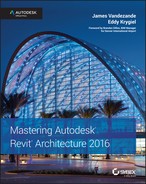
This workflow applies to a carriage support as well. Repeat the previous steps, but look for those support types under Families ➢ Stairs ➢ Carriage. As a final note about custom support profiles, you must ensure that the proper usage property is specified in the profile family when you are creating the shape. In the Family Editor, click the Family Category And Parameters button in the ribbon and make sure the Profile Usage parameter is set to Stair Support (Figure 15.33).
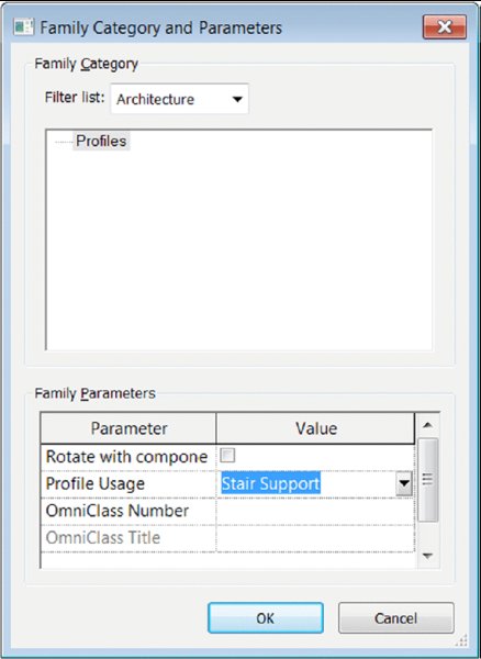
Figure 15.33 Setting the Profile Usage parameter for a custom support profile
USING BALUSTERS AS TREAD SUPPORTS
Common tread shapes can be pretty boring, so let’s move on to custom tread conditions. In situations where you need to be a bit more inventive, you’re going to create a custom baluster. This technique can either create a custom support element for the default treads or it can indicate the actual tread.
But instead of the baluster being vertical, it’s going to be horizontal. This horizontal baluster will be used in conjunction with the default tread. This baluster may even completely envelop the tread (Figure 15.34).

Figure 15.34 Baluster as tread support
First, we need to discuss a few rules for creating a customized tread support for the default tread:
- Not every baluster needs a railing. If your baluster support isn’t going to be a part of the “real” railing, just create another “railing” that is hosted by the stairs. Sketching another path for your custom railing that only contains the tread support baluster can accomplish this in a few steps. Another technique is to copy an existing railing, then paste it to the exact same location, and change the type to your custom supporting baluster.
- The baluster family template needs to be used for the component that will act as the tread support. Otherwise, it can’t be associated to the railing.
- If you have a complex support element, it may be helpful to model the desired support element as a generic family. When you’ve finished, nest this generic element into the baluster family. You may want to do this because the baluster templates have hardwired reference planes and parameters (which is fine if you’re making a baluster that needs to geometrically flex). But in this case, we’ve found that these reference planes and parameters may cause your baluster to fail when you load it in the project as a result of these parameters flexing. By modeling the geometry elsewhere and nesting it, you avoid this hassle because it moves as a single component.
- Designating the level of detail is crucial. Assigning smaller model elements to only appear when the Detail Level of a view is set to Fine will result in much faster graphics regeneration, view panning, and model rotation. So if you’re nesting one component into another family, the detail that you’re assigning at the deepest level will be respected through nesting (Figure 15.35).

Figure 15.35 Single component that will be used as a tread support
Once the component is complete, you can nest it into a baluster template, as shown in Figure 15.36. If necessary, it’s also possible to assign parameters to the dimensions in the nested configuration.

Figure 15.36 The generic model nested into a baluster family
The completed stairs are shown in two different configurations in Figure 15.37. Many configurations are possible once you correctly define a single stair type. If you’d like to investigate this stair further, it’s in the Chapter 15 folder on the book’s web page, and the file is called c15-Angled-Support-Stair.rvt.

Figure 15.37 Completed stairs with angled tread supports
A custom baluster support might be modeled to contain the real balusters that are intended to support railings. This can simplify and shorten modeling time. In the example shown in Figure 15.38, the baluster support geometry also contains the railing elements on both the right and left sides. If you’d like to investigate this stair further, it’s in the Chapter 15 folder on the book’s web page; the file is called c15-Support Tread.rfa.

Figure 15.38 Complex tread support with balusters
The previous support baluster can be brought together with a custom profile for the center stringer, handrails, and glazed panels to form a complete stair and railing design (Figure 15.39). You can download this example from the Chapter 15 folder on the book’s web page; the file is called c15-Center Baluster Support.rvt.

Figure 15.39 Completed stair design with custom tread support as a baluster
Once you’ve begun to experiment with creating balusters as tread supports for stairs, you’ll notice you have options for making more complete and finished conditions.
Start and end posts are useful and can help complete the structure of your custom railing and baluster system, particularly if you want to properly anchor and connect your custom stair and railing. The elements shown in Figure 15.40 are the start and end posts to anchor a custom railing and a baluster that will serve as the tread with integrated support. It builds on the previous example of using a baluster as a support element for a tread.


Figure 15.40 Custom post and baluster families
To finish this stair, you need to create start and end posts that anchor the stair. As with the previous handrail-join exercise, you’ll want to model the bulk of the custom stair with the custom railing. Then you’ll export the stair parts for importing into the baluster template (or the generic model template that will be nested into the baluster template).
Figure 15.41 shows the results after the start and end posts and custom baluster families are applied to a completed stair design.

Figure 15.41 Finished stair with custom start and end posts
When it all comes together, the results can be elegant and interesting. All of this is available through the default Stairs tool. You can download this stair from the Chapter 15 folder on the book’s web page; it’s called c15-Tube Stair.rvt.
Now let’s go one step further. There’s no reason that the baluster support element needs to exactly conform to the shape of the tread. And there’s no reason that the support element can’t contain the actual baluster that is intended to support the handrail.
Take a look at the support element in Figure 15.42. Not only does it contain the support element, but the support element has been modeled to exceed the shape of the tread that will be modeled by the Stairs tool.

Figure 15.42 Support and baluster as a generic model
Keep in mind that we’ve modeled the support element as a generic model and then nested it into a baluster post template (Figure 15.43). Again, this keeps the baluster together so it’s not affected by the built-in reference planes and parameters.

Figure 15.43 Baluster and support nested into a baluster post template
Once this custom baluster post is loaded into the project, associate it with the stair and its railings. Remember to select the One Baluster Per Tread option. When finished, the default tread is an inlay to the more complete tread support (Figure 15.44). In more complex conditions, it may be desirable to envelop the entire tread with the support geometry. Doing so will allow you to create complex tread shapes that are not dependent on the default tread and use the functionality of the stair and railing objects to properly locate, rotate, and elevate each of your custom treads. If you want to examine this stair further, check out the file c15-Curved Tread Support.rvt in the Chapter 15 folder on the book’s web page.

Figure 15.44 Finished stair with integrated baluster and support
Figure 15.45 shows an example using this technique. The tread support elements have been modeled using blends in order to sweep under the metal plate while changing direction from vertical to angle. This will accommodate the angled pipe rail that will support the stair.

Figure 15.45 The top and underside of a tread support
Treads come together in a particularly interesting stair and railing configuration. There is obviously a more conventional outer railing for this stair. But the inner railing doesn’t have any elements that occur at hand height. The entire inner railing exists to support the baluster supports (which in turn support the default treads). The end post is being used to anchor the entire structure through the second level. You can find this example, c15-Highlights.rvt, in the Chapter 15 folder of the book’s web page. Figure 15.46 shows the finished stair. The large structural element is actually a baluster that’s been designated as the end post.

Figure 15.46 Completed stair with large end post
Creating Stairs with Other Tools
We’ve discussed a number of different ways the parts of stairs can be manipulated and created. As we approach alternate modeling techniques with the goal of creating elegant stairs, understand that the metadata may not correspond to the geometry. This is usually the only option to complete a design where there are limitations to the default tools while avoiding the need to resort to strictly 2D representation. Because the metadata—the information part of BIM—isn’t being coordinated properly, you’ll want to take particular care with regard to tagging and scheduling.
A solid spiral wall can be used as a railing, or a support element can easily be created in the Family Editor and then associated with the stair as a start post. Of course, this geometry could also be created as an in-place family, but then you’d lose the advantage of being able to quickly and easily relocate the stair in your project (or create a multistory condition).
In Figure 15.47, you can see part of a spiral stair with default treads and supports modeled as balusters with the Railing tool.

Figure 15.47 Baluster used as a support element
Rather than create the spiral wall (Figure 15.48) as an in-place family under the stair, the form was modeled as a baluster post in order to associate it with the beginning of the railing being used for the support brackets.

Figure 15.48 A series of swept blends modeled in a post family.
To make sure the path is correct, the run line of the stair is copied into the post family named Spiral Start Post (Figure 15.49). Now you can use this path as you create each of the blended sweeps (creating only one swept blend per path). In this case the blends are being modeled so that there’s a 3" (75 mm) gap between the undersides of the default treads.

Figure 15.49 Copy the stair run path into the post family.
Figure 15.50 shows what you get when it all comes together. The swept blend has been created in a post template. This post is then loaded into the project environment and associated with the railing type named Support Baluster that contains the baluster definition with the support brackets named Custom Baluster. This is also a useful technique if you have to create walls that need to follow either side of a stair. If the condition exists only once, you may opt to create this as an in-place component.

Figure 15.50 Finished stair condition
But if it occurs more than once or might be rotated and relocated (as well as occur on many levels), we recommend that you create this as part of the stair and railing definition. Then it will be easier to maintain relationships throughout the project. To investigate this stair, download the c15-Concentric Stair.rvt file from the Chapter 15 folder on the book’s web page.
Now let’s put it all together. When it comes to feature stairs, few stairs are as immediately recognizable as the glass stairs and walkways that have been designed for Apple by Bohlin Cywinski Jackson (Figure 15.51). Although these stairs seem incredibly challenging, there’s very little about the feature stair at Apple’s Fifth Avenue retail store that can’t be modeled out of the box!

Figure 15.51 Feature stair at the Apple Store in New York
Source: Image courtesy of Dougal McKinley
Even though the stairs are very sculptural, there are quite a few repetitive relationships that are easily identified and defined. Of course, what doesn’t strictly conform to the rules of the Stairs tool will have to be modeled elsewhere. First, let’s model the treads and landing. We’re assuming some dimensions since we don’t have the actual drawings or measurements to work from: 2" (50 mm) thick, 6'-0" (2 m) wide, and a 4'-0" (1.2 m) interior radius (Figure 15.52).

Figure 15.52 Finished tread configuration
A small support pin is used to support the treads. One pin per tread supports the inner portion of the tread, but two pins per tread support the outer portion (so right away we’ll have to create two separate handrail types for the stair). Figure 15.53 shows the pin family.

Figure 15.53 Support pin as a baluster
With this in mind, we’re able to place the pin as a baluster after modeling it as a generic model and then nesting it into a baluster family template (not a baluster post), which will allow it to conform to the elevation of the landing. Since the pin is so small, it is only assigned to the Fine level of detail, so it doesn’t show up unless the Detail Level property of a view is set to Fine.
As just mentioned, two handrail types are needed because they will host different baluster definitions. The inner handrail has one pin support per tread, whereas the outer handrail has two pin supports per tread (Figure 15.54).

Figure 15.54 One and two pins per tread with handrails
As for the start and end posts, two families are needed: one for the start configuration and another for the end. They include the horizontal extension beyond the end of the railing sketch. Once you’ve added these posts, the stair really starts to come together (Figure 15.55).

Figure 15.55 Treads, support balusters, and railings
This concludes the portion of the stair that can be modeled out of the box. Export this 3D context for the remainder of the stair, which will be modeled as a generic family and then nested into a baluster post and assigned as a start post. There’s a third railing in this stair (which contains no railing profile). This “invisible” railing is hosted by the stair and creates the remaining elements, as shown in Figure 15.56.

Figure 15.56 Glazed panels with connections
Two swept blends form the upper and lower glazed and curved panels, and a regular sweep forms the panels at the landing. At the same time, a single extrusion forms the center, glazed cylinder. When all this geometry is modeled, a single void (in plan) is extruded vertically and creates all the discrete panel separations at one time.
The panel supports and the actual balusters that will support the railing are modeled elsewhere and then nested into this family. This approach will allow the object to be quickly updated from a single location. Keep in mind that the handrails in the project will be used to host the baluster “pins” (one or two per tread); the handrail supports will be nested into this family. Each panel has a single baluster element (Figure 15.57).

Figure 15.57 Final geometry before nesting into the baluster family
Now you’re ready to associate this baluster post with a center railing (which contains no handrail). A couple of details are shown in Figure 15.58.

Figure 15.58 Completed stair and details
Figure 15.59 shows the finished stair. Yes, there’s a lot more to the stair than this: the platform, elevator, landing, and so on. At the end of the day, there’s nothing to keep you from modeling the entire stair in the Family Editor and then placing it in the project as a generic model. In some cases, this is exactly the kind of modeling control that complex and sculptural stairs need. Are they stairs? No, they’re probably more like inhabitable sculpture. And trying to design sculpture in a spreadsheet is harder than just modeling what you want in the Family Editor. “But what about parameters?” you ask. Well, sometimes defining the parameters takes more time than making the change manually in one place and then reloading the results into your project. If you’re interested in downloading this stair, it’s in the Chapter 15 folder of the book’s web page; the file is called c15-Apple Stair.rvt.
Figure 15.59 Completed stair, panels, and core
Annotating Stairs
Stair treads are annotated using the Tread Number tool, which is located in the Annotate tab of the ribbon. You can use this tool from any plan view. When this tool is activated, place a string of labels on any component stair by simply selecting the stair run. The tread number annotation can be placed at the sides, the middle, or the quarter points along the run width (Figure 15.60).

Figure 15.60 The tread number annotation counts individual treads or risers.
To customize the tread number annotation, select a tread number instance you have already placed in a view and you will find additional parameters in the Properties palette, such as Number Size, Orientation, and Display Rule (Figure 15.61). You can also change the start number in the Options bar.

Figure 15.61 Customize the tread number in the Properties palette.
The arrow and label for stairs are controlled independently of the stair type for component stairs. If you created a stair with the Stair By Component tool, you will notice that the arrow and label can be selected separately. When they’re selected, you can change the type of annotation in the Type Selector, and you have additional parameters in the Properties palette (Figure 15.62).

Figure 15.62 Settings for the stair path annotation
Because the stair path annotation for component stairs is a separate element, it can simply be deleted when you don’t need it in a view. To replace the annotation, go to the Annotate tab in the ribbon, and from the Symbol panel click the Stair Path button and pick a stair to apply the annotation.
Finally, the cut mark that displays with stairs in a plan view can be slightly customized. The settings for cut marks are stored in yet another system family that is nested within the component stair type properties. In the Project Browser, navigate to Families ➢ Stairs ➢ Stair Cut Mark to find the types available in the default project template. Double-click any of these types to observe the properties for customizing the cut mark (Figure 15.63). To assign a Cut Mark Type value, open the Type Properties dialog box for a component stair type and look for the Graphics heading.

Figure 15.63 Parameters for the Stair Cut Mark family
Creating Railings
Railings can be created anywhere in a project. They can be placed on stairs, ramps, floors, and roofs, but they are not hosted elements. The railing does not need to be dependent on a host object to exist. From the Architecture tab in the ribbon, you will find the Railing tool in the Circulation panel. Click the Railing flyout and you will see Sketch Path and Place On Host.

You would use the Sketch Path tool to create a railing on a flat surface such as a slab edge. When the Place On Host tool is activated, you must select a stair or a ramp and the placed railing will follow the slope of the stair or ramp. If you choose this second option, notice in the contextual ribbon that you have the option to specify whether the railing will be oriented above the tread or the stringer (Figure 15.64)—you can always modify this after the railing has been placed.

Figure 15.64 Set options for tread or stringer placement of railings.
Before we create a railing, we should explain the placement of a railing on a stair a little further. When you use the Place On Host method, the railing path is automatically assigned to the edge of the stair that represents the outside face of the tread and the inside face of the stringer (if one is defined). The railing orientation is simply flipped to either side of this path—toward the tread or toward the stringer. In the Properties palette, you will find a parameter named Tread/Stringer Offset that is set to –0'-1" (–25 mm) by default. Most rail and baluster families are developed along a center axis; therefore, the Tread/Stringer Offset value pushes the railing to one side or the other of the railing’s path. To modify this orientation after a railing has been placed, select a railing and either click the flip arrow that appears in the view window or right-click and select Flip Orientation from the context menu. The Tread/Stringer Offset value will remain the same no matter which way the railing is oriented.
When you use the Place On Host option of the Railing tool, be aware that you will not be able to click on stairs that already have railings. You will not be prompted with a warning or an error—you simply can’t select the host object. If you do find a stair or ramp on which you would like to place a railing, also be aware that one railing type will be applied to both sides of the host object. If you want a different railing for the outside of a stair element, you can use the Place On Host tool and change one of the rails with the Type Selector later. If you are using the Stair or Ramp tool, you can choose the option to automatically place railings when the stair or ramp is created. When either of these tools is activated, you will find the Railing button in the contextual tab in the ribbon (Figure 15.65).

Figure 15.65 Integrated railings can be defined in the Stair or Ramp contextual ribbon.
Click this Railing button in the contextual ribbon and the Railing dialog box will appear (Figure 15.66). From the drop-down list, you can choose any railing type defined in the project or choose Default or None. For stairs only, you can define the placement of the railing to be along the treads or the stringers.

Figure 15.66 Choose a railing to be placed with a stair or ramp.

Figure 15.67 Draw two new sketch lines to extend the railing path.

Figure 15.68 The completed railing has been extended onto the landing.
Where would you need to use these sketch segment options for railings? You can use them to customize a railing that has been placed on a host. For example, you may need to continue a railing from a stair run onto a flat landing. Let’s try this out in an exercise:
- Download and open the file
c15-Railing-Tool.rvtorc15-Railing-Tool-Metric.rvtfrom this book’s web page. - There is a sample stair from Level 1 up to Level 2, and a railing has already been placed on the stair. Open the Level 2 floor plan. Select the railing along the outer edge of the stair and click Edit Path on the Mode panel in the contextual ribbon.
- In the Draw panel of the contextual ribbon, select the Line tool and draw a line from the end of the existing railing sketch, as shown in Figure 15.67. Include a short segment extending in the direction of the existing sketch line, and then draw the next segment to the perpendicular edge of the floor landing.
- Select both new sketch segments you drew in step 3, and from the Options bar, set the Slope option to Flat. Now, this step may not be necessary because the railing sketch should be aware that the floor below is flat, but this is the best way to ensure consistent results with manually sketched railing paths.
- Click the green check mark in the contextual ribbon to finish the sketch, and activate the Default 3D view to observe your results (Figure 15.68).
Creating a Custom Railing
Now that we’ve reviewed the major components of stairs and railings, let’s create a rail. The rail we’re going to make is a stainless steel cable railing with flat steel stock posts. Our completed railing will look like Figure 15.69. You can adapt the workflow we’re going to complete to create just about any typical railing.

- To begin, we need to build some of the components of the railing. The rail will have a stainless steel top rail, which is already part of our default project template. However, we will need to create the cables and the posts. Let’s start with the cable. Select the Application button and choose New ➢ Family. Select the
Profile-Rail.rftorMetric Profile-Rail.rftfamily template. You’ll see two intersecting reference planes and some text describing the Rail Centerline and the Rail Top. - We’re going to create the cable, which is a simple, circular extrusion. On the Create tab, select the Line tool from the Detail panel. Use this tool to create a circle that is ½" (12 mm) in diameter (Figure 15.70). Save this file as
Cable.rfa. - We need to do a similar thing to create the stainless steel posts. Select the Application button again, choose New ➢ Family, and select
Baluster-Post.rftorMetric Baluster-Post.rftfrom the list of new families. This will open the Left elevation view of the family. From the Project Browser activate the Ref. Level plan. We’re going to make an extrusion that will become our baluster. -
You’ll notice that the tools in this family are different from those in the profile family we just created. The profile family was simple 2D linework that will extrude along a path to create the cable. In this baluster family, we’re going to create a 3D element. In the plan view, choose Extrusion from the Forms panel of the Create tab. Using the intersection of the reference planes as the lower-left corner of the form, create a box that measures 1 ½" × ½" (38 mm × 12 mm). The shape should look like Figure 15.71. Don’t worry about adding the dimensions.

With the shape created, click the green check mark in the contextual tab of the ribbon to make the form. You’ll see your box in plan, but for the next step, activate the Front elevation view from the Project Browser. You’ll see a short extrusion of the form you just created with the base at the Ref. Level. You’ll also see two reference planes above the form—one represents the typical railing height and the other (the higher one) represents the typical guard rail height.
- Switch to the Modify tab in the ribbon and choose the Align tool, and align the bottom of the extrusion to the Ref. Level and the top of the extrusion to the lower reference plane (Figure 15.72). Make sure to activate the lock after each alignment. When you’ve finished, save the new family as
SS-Post.rfa. - With both of these families created, you can now make the railing. Open a new project file and load both of these families into it. Choose the Railing command and select Sketch Path. Draw a simple line of any length. That will become your railing. Now, while you’re in the Railing command, you need to create a new system family type to be your rail. Since this is a system family, like walls or floors, you need to create the rail by duplicating an existing one. Choose Handrail – Pipe and select Edit Type from the Properties palette.
- In the Type Properties dialog box, choose Duplicate and name the new family Cable Rail. Click OK to close the Name dialog box. The family you duplicated shares many of the features of the rail you want. The top rail is a circular pipe, and the rail itself is 3' (900 mm) tall. You need to modify the Rail Structure (Non-Continuous) and the Baluster Placement options. Begin with the Rail Structure (Non-Continuous). Choose the Edit button to open the Edit Rails (Non-Continuous) dialog box. This dialog box has rails that are spaced 6" (150 mm) apart using the Circular Handrail profile. You want to change a few things here. First, under the Profile heading, change the profile to Cable : Cable, which is the railing profile you just created. You can do that by selecting Cable : Cable from the drop-down menu. Do this for all of the profiles.
- Next, you want to change the rail spacing from 6" (150 mm) to 4" (100 mm). Modify each of the rails to show a 4" (100 mm) increment. Your rails from bottom to top will read as follows:
- 4" (100 mm)
- 8" (200 mm)
- 1'-0" (300 mm)
- 1'-4" (400 mm)
-
1'-8" (500 mm)
This won’t be sufficient to make it to the bottom of the top rail, so you’ll need to add more rails. Click the Insert button to add three more rails: Rail 6, Rail 7, and Rail 8. Make the profile for all of those Cable : Cable and give them a height of 2'-0" (600 mm), 2'-4" (700 mm), and 2'-8" (800 mm), respectively. Here you can also define the materiality of the rail. We’ve applied Stainless Steel to all of the rails. The completed dialog box will look like Figure 15.73. Once you’ve finished, click OK.
- Now you need to adjust the baluster. In the Type Properties dialog box, at Baluster Placement, select Edit. This opens the Edit Baluster Placement dialog box.
- First, like in the rail, you need to modify the family that is used to make the baluster. From the Baluster Family drop-down menu for both the Main Pattern (the upper portion of the dialog box) and the Posts (the lower portion of the dialog box), change the family to SS Post : SS Post. Also, you want the post centered under the top rail. Because you built the post family to one side of the reference planes, you need to offset the post to center it. In the Offset column on the far right, enter a value of ¾" (19 mm). The finished dialog box will look like Figure 15.74.
- Click OK twice to finish the rail. The completed cable railing will look like Figure 15.75. You can see how quick and easy it is to create some simple railings. You can find the finished railing,
c15-SS Railing.rvt, on the book’s web page.

Figure 15.69 The finished cable railing

Figure 15.70 The cable profile family

Figure 15.71 Using the Extrusion tool to create the post

Figure 15.72 Align the post to the reference planes.

Figure 15.73 The completed Edit Rails (Non-Continuous) dialog box

Figure 15.74 The completed Edit Baluster Placement dialog box

Figure 15.75 The completed railing
Creating Glass Railings with the Curtain Wall Tool
The most challenging railings often require exceptions to the rules. This usually means you’re trying to manually locate balusters or use panels that are not part of the routine railing definition. If you tried to define each of these exceptions as a different railing type, your project would be overflowing with railing types. The best solution for these types of railings is to diverge from the Railing tool and use the Curtain Wall tool.
By using the Curtain Wall tool, you’ll be able to create railings by modeling the balusters and panels inside the Curtain Panel family template (Figure 15.76). Another nice feature about this technique is that the railing is a room-bounding element because it is actually a wall. That makes this perfect for mezzanine conditions that require area calculations—certainly more efficient than creating redundant room-separation lines!

Figure 15.76 Curtain panel as a railing
Start by creating a single panel using the Curtain Panel template. The family may contain not only the panel for the railing but also the balusters. Once you load this panel into your project, you can create curtain walls with predefined panel widths (Figure 15.77).

Figure 15.77 Curtain panel railing with custom baluster locations
Because curtain panels allow you to unpin predefined grids (as well as create other grid locations), you’ll be able to quickly and easily make exceptions to the rules that you previously defined (Figure 15.78) and create several unique baluster locations specific to the installation.

Figure 15.78 Adjusted baluster locations
When you’re creating railings as curtain walls, be sure to filter your schedules accordingly to prevent these “railings” from being included in your curtain wall schedules. If you want to download this example project, it’s in the Chapter 15 folder on the book’s web page and is named c15-CurtainWall-Railing.rvt.
These outside-the-box techniques should give you some great ideas for making custom railings faster and more interesting than you could ever have imagined.
Using the Railing Tool for Other Objects
Currently, Revit software doesn’t have a specific tool to allow components to be quickly and easily distributed along a user-defined path. In some cases you could use line-based families, but these don’t work in curved conditions. You could also experiment with adaptive components in the conceptual massing environment, but that could be too complicated for a simple, repeating element. In the meantime, consider using the Railing tool to distribute elements along paths for a variety of uses besides just for railings.
When using railing functionality outside of a railing to distribute elements along paths, keep in mind these three rules:
- You’ll probably want to nest your family into a baluster family template (rather than creating it directly as a baluster). This is because the existing parameters within the baluster family can cause your geometry to fly apart if it needs to move up and down as a single element.
- Don’t expect your nested element to schedule or tag. If you need the elements to schedule or tag individually, you probably want to place them individually (or use another technique, like a line-based family).
- Don’t share parameters of nested families in an attempt to schedule. Your element won’t schedule properly.
In some cases, you’ll want the railing family to have associated profiles, like the shading device in Figure 15.79. The railing profiles are used to create the shading fins, and the balusters are the support elements.

Figure 15.79 Railing as shading device
Using railings to quickly and evenly distribute components along a path is great during design and allows for quick iteration. Outdoor elements like lampposts are particularly appropriate for distributed placement (Figure 15.80). In this example, a lamppost has been nested into a baluster family.

Figure 15.80 Lamppost nested into a baluster family
Once this lamppost has been nested in the baluster family, you’ll be able to create a custom “railing” with the lamp designated as the “baluster.” This will allow you to quickly and easily distribute lampposts along a sketch at specific intervals that can be modified as a parameter. So, for example, if the lamppost was originally distributed on 60' (18 m) centers, you could very quickly redefine it to occur on 40' (12 m) intervals (Figure 15.81).

Figure 15.81 Lampposts distributed along a path as a baluster family
You can use this for any repetitive elements that must be placed on center and evenly distributed along a path. Other uses might include pipe bollards and outdoor planting.
Even a design pass at light rail tracks (including railcars) can be distributed along paths (Figure 15.82). In this case, the rail sleepers are balusters, and profiles are used to create the rails and the rail bed. The monorails are easy too. The vertical supports and railcars are balusters, and the suspended track is the rail profile. This file can be downloaded from the Chapter 15 folder on the book’s web page. Look for the c15-Monorail and Railway Railing.rvt file.

Figure 15.82 Transportation components as railings
The Bottom Line
Understand the key components of stairs and railings. Having a complete understanding of the components of stairs is important. You don’t want to set about breaking the rules until you understand how best (and when) those rules can be broken.
Master It What are the essential parts of stairs?
Understand the different stair tools and apply them to custom designs. Designing in a spreadsheet is hard. Step back and consider what you’re trying to accomplish. If you’ll look at the components that make up stairs, you’ll see some interesting opportunities.
Master It How would you create a continuous tread that wasn’t monolithic? What would you do if you wanted to create a custom stringer? Are balusters always vertical and used to support handrails? What if your particular stair just can’t be modeled in the Stairs tool?
Design railings and use the Railing tool for other model elements. From model patterns to geometric intricacy, there’s a lot that can be created with the Railing tool. When this doesn’t work, look to the Curtain Wall tool for “railings” that can contain space and allow “balusters” to be conveniently unlocked.
Master It Why would you not use a railing to manage repetitive relationships? What if you need to accurately distribute geometry along a path?
Implement best practices. There are specific best practices when creating custom stairs and railings. Pay attention to nesting geometry, maintaining the right level of detail, and filtering schedules so the metadata ends up in the right place.
Master It Is it possible to create solutions that are too efficient? What’s the big deal with detail levels? And finally, what’s the most important thing to remember before creating an elegant workaround?