In the previous chapter, we discussed working with others in an environment in which all parties use Autodesk® Revit® Architecture software; however, often you’ll need to work with data from other software platforms. For example, you may need to coordinate data from other disciplines, reuse legacy data, or integrate disparate design platforms. There are several ways to use external data within your Revit Architecture model in both 2D and 3D. We will discuss not only the methods of importing and exporting data but also when to use each method and the reasons for using specific settings.
In this chapter, you’ll learn to:
Use imported 2D CAD data
Export 2D CAD data
Use imported 3D model data
Export 3D model data
Work with IFC imports and exports
Examining Interoperability on a BIM Curve
Based on a 2007 study on interoperability in the design and construction industry, McGraw-Hill Construction reported annual losses of $9.1 billion in the building industry due to insufficient interoperability. You can find the full report online (http://www.aia.org/aiaucmp/groups/aia/documents/pdf/aias077485.pdf). This study underscores a problem that building information modeling (BIM) as a whole is designed to address. Adequate interoperability will help rectify the problem illustrated in Figure 7.1, sometimes known as the BIM curve. In Figure 7.1, the downward spikes in the lower line at the end of each project phase represent a loss of knowledge and acquired data. This loss usually occurs when a project is exported from BIM to a 2D CAD format or is printed to paper. Project data is then gradually reconstructed in another software platform. The upper line represents a more ideal paradigm where data and knowledge are gradually increased throughout the life of the project—a paradigm supported by BIM and full interoperability.
Figure 7.1 The BIM curve shows loss of data without interoperability at project milestones.
Source: P. Bernstein, Autodesk AEC Solutions
Although full interoperability between BIM platforms is the ideal scenario, we realize that you are likely to be working with constituents who are using 2D CAD or non-BIM 3D software.
Inserting CAD Data
Although Revit software provides ample means to generate 2D documentation based on a rich multidimensional (3D, 4D, 5D, and so on) model, there are a few real-world scenarios in which CAD data must be integrated with the building information model. Such scenarios might include the following:
Using CAD details developed within your firm
Coordinating with other firms using CAD software
Converting projects from CAD to a Revit model
Using external modeling tools for conceptual massing
Using complex component models from other software
Using Predefined Settings for Inserted CAD Data
When you are inserting data from a DWG or DXF file, you can establish some predefined settings to control its appearance within the Revit environment. Some settings are controlled at the time you insert a CAD file, but other settings can be configured more deliberately in saved configuration files. The two ways you can configure this data are by mapping layer colors to Revit line weights and converting font types.
MAPPING LAYER COLORS
For inserted CAD files, layers within the file are assigned a Revit line weight based on the weight assigned to each layer by the CAD software application that created the files. If the layer line weights are set to Default in the CAD file, they will follow a translation template you can configure that maps the layer colors to Revit line weights. To access these settings, select the Insert tab and click the dialog launcher at the bottom right of the Import panel. Doing so opens the Import Line Weights dialog box, shown in Figure 7.2.
Figure 7.2 Defining settings for imported DWG/DXF line weights
As you can see in the title bar of this dialog box, these settings are stored in a text file (TXT) in the Data folder where Revit is installed. There are several predefined text files based on international CAD standards for layer color:
AIA (American Institute of Architects)
BS1192 (British Standard)
CP83 (Singapore Standard)
ISO13567 (International Standards Organization)
Click the Load button to select one of these predefined line weight templates or your own. Based on the unique needs of some projects, you might also consider creating customized import setting files and storing them along with the rest of your project data.
MAPPING FONT TYPES
Another important aspect for inserted CAD data is the ability to map shape-based fonts to TrueType fonts. Usually a remnant of older CAD standards based on graphic performance, CAD files may contain fonts such as Simplex, RomanS, or Monotxt that do not have matches in standard Windows fonts. The shxfontmap.txt file defines the mapping of TrueType fonts as substitutes for each specified SHX font. You can find this text file at C:ProgramDataAutodeskRVT 2016UserDataCache.
If your firm frequently uses CAD data as an integrated part of your final documentation, the shxfontmap.txt file should be configured to map your standard CAD fonts to your standard fonts used in a Revit project. This file should then be copied to the workstations of all team members using Revit software. Failure to do so may result in undesirable results when using CAD files in a worksharing environment.
Importing vs. Linking
You can insert CAD data into the Revit environment in two ways: importing and linking. Each method has advantages and disadvantages.
Importing Similar to the using the Insert command in Autodesk® AutoCAD® software, importing data integrates the CAD data into the Revit project but does not allow the imported data to be updated if the original CAD file is modified. In such a case, the imported data would have to be deleted and reimported. It also does not give you an easy way to purge the layers, linetypes, and hatch patterns of an imported file if it has been exploded and then deleted.
Linking A linked CAD file in a Revit project is analogous to an external reference (Xref) in an AutoCAD project. When the original CAD file is modified, its reference is automatically updated in the Revit environment. Linking also allows you to easily unload or remove a file when it is no longer needed, which will leave no trace of the file’s contents after removal.
Linked data cannot be modified directly in a Revit project unless it is converted to an import in the Manage Links dialog box (Insert ➢ Manage Links) and then exploded. We discuss this process in the “Manipulating Inserted CAD Data” section later in this chapter. As an alternative, it can be modified in its original authoring application and then updated within Revit.
Linking is the preferred method for external data integration; however, too many linked files will make it slower to open a Revit project. For example, ceiling plan fixture layouts may change with every design iteration (where linking is preferred); however, standard details that all share a minimal amount of standardized layers, linetypes, hatch patterns, text, and dimension styles might be better suited as imports.
Using Options During Importing/Linking
After you have configured the necessary settings for inserted CAD data and decided whether to import or link, you need to understand certain options during the import/link process. We’ll discuss the preferred settings for each of the options based on real-world situations in the sections “Using Inserted 2D Data” and “Using Inserted 3D Data.” To place your first CAD file into a Revit project, switch to the Insert tab and select either the Link CAD or the Import CAD button. No matter which tool you use, there will be several important options at the bottom of the respective dialog box, as shown in Figure 7.3.
Let’s examine the meaning of the settings in this situation:
Current View Only When this option is selected, the linked or imported file can be seen only in the view in which it was inserted and is thus considered a view-specific element. In a worksharing-enabled project, this data will be assigned to the view’s workset. More often than not, you will want to choose this option to limit the number of views in which the referenced data will appear. If you need this data in other views, you can copy and paste it from one view to another.
If the option is not selected, the linked file can be seen in all views, including 3D, elevations, and sections. In a worksharing-enabled project, this data will be assigned to the active workset. A benefit to using links in a worksharing environment is the ability to create a workset specifically for linked data and uncheck its Visible In All Views option. The CAD file(s) placed in this manner will not appear in every view but are available when you need them by adjusting the workset visibility in the Visibility/Graphic Overrides dialog box.
Colors Colors don’t matter for CAD files being used as a basis to create a Revit model; however, using Invert or Preserve may help distinguish the CAD data from the modeled elements during the conversion process. If you are going to integrate the inserted data with other elements in your project for final design or construction documentation, you’ll want to select the Black And White option, because printing from Revit is mostly WYSIWYG (what you see is what you get). Read the section “Using CAD Data for Coordination” for more detailed recommendations on this process.
Layers/Levels These options allow you to import or link all the layers, only the layers visible when the CAD file was last saved, or a selected group of layers you choose from the linked file in a separate dialog box. (Layers is a DWG-based term. Revit software supports the same functionality with levels from DGN files.)
Import Units For CAD files generated in an original program (that is, DWG from AutoCAD or DGN from MicroStation), the Auto-Detect option works well. If you are linking CAD data that has been exported from a different program, such as DWG exported from Rhino, you should specify the units relative to the respective CAD file.
Positioning To maintain consistency in a multilevel project during a CAD-to-Revit coordination or conversion process, you should use Auto – Origin To Origin or Auto – By Shared Coordinates. Origin To Origin will align the world coordinates origin of the CAD file with the project internal origin. Although Autodesk claims Auto – By Shared Coordinates is only for use with linked Revit files, it can be used with CAD files if the rotation of true north becomes inconsistent using the Origin To Origin option.
Place At This option is available only if Current View Only is not selected; it specifies the level at which the inserted data will be placed.
Correct Lines That Are Slightly Off Axis Selecting this option automatically corrects lines that are slightly off axis when you import or link CAD geometry. This option is selected by default and will help keep your Revit elements (such as walls or linework) that tie to CAD lines from being askew; however, you may need to consider this option carefully. If the CAD data you are inserting is intentionally off axis, the corrections may lead to inaccurate results. For example, a site plan may have property lines that are a fraction of a degree from being orthogonal, but they must be maintained for accurate building placement in your Revit project.
Orient To View This option may be used if True North has been rotated away from Project North. If that is the case and you are linking a CAD file into a view that is set to True North, deselect this option to align the CAD file’s World Coordinate System with True North as defined in your Revit project.
If you do check the Orient To View option, the CAD file will align with Project North regardless of the view orientation.
Manipulating Inserted CAD Data
Once you have CAD data imported or linked into a Revit project, you have several ways of manipulating the data to suit your needs:
Foreground/Background This setting applies only to linked or imported CAD files placed with the Current View Only option. With the inserted file selected, a drop-down menu will appear in the Options bar so you can adjust whether the data appears above or below your modeled Revit content. You can also access this setting in the Properties palette when the inserted file is selected.
Pay close attention to this option when integrating 2D CAD data with an existing Revit model—sometimes linked or imported CAD data may not appear at all until you set the option to Foreground because of floors or ceilings obscuring the 2D data.
Visibility of Layers/Levels The layers or levels within a linked or imported CAD file can be accessed in two ways, the easiest of which is the Query tool. First, select a linked or imported CAD file; then, from the contextual tab in the ribbon select the Query tool and pick an object in the CAD file.
You will see the Import Instance Query dialog box (Figure 7.4). Using this tool, you can hide the layer or level by clicking the Hide In View button. The Query tool will remain active even after you click any of the command buttons in the Import Instance Query dialog box, and you must press the Esc key or click the Modify button to end the command.
Figure 7.4 Querying objects within a linked CAD file
The second way to make layers or levels in imported or linked CAD files invisible is to use the Visibility/Graphic Overrides dialog box by switching to the View tab and selecting Visibility/Graphics from the Graphics panel. Once the dialog box opens, select the Imported Categories tab, as shown in Figure 7.5. Only the inserted CAD files that are visible in the active view will be listed in this tab. Expand any listed file to expose the layers/levels within that file, and use the check boxes to customize visibility of the link within the current view. This method is the only way to restore visibility of layers/levels that were hidden with the Query tool.
Figure 7.5 Controlling visibility of layers within imported objects
Graphic Overrides If you need to change the appearance of the content within a linked or imported CAD file, you can accomplish that at the project level or within an individual view. To change a CAD file’s appearance throughout the project, select the Manage tab on the ribbon, and click Object Styles in the Settings panel. Select the Imported Objects tab (Figure 7.6), and expand any of the imported or linked CAD files to change the color, line weight, line pattern, or material of the layers/levels within the referenced file. Changing these properties in the row of the filename does not affect the contents of that file. You can also apply these settings in a specific view using the Visibility/Graphic Overrides dialog box.
Figure 7.6 Changing the graphic appearance of imported layers via object styles
Exploding Although we do not recommend exploding CAD data within a Revit project, you can do it to facilitate the modification of such data. Linked content must first be converted to an import in order to be exploded. You do this by selecting the Insert tab on the ribbon, choosing Manage Links from the Link panel, choosing a listed link, and clicking the Import button. To explode the imported file, select it, and choose Explode ➢ Full Explode or Partial Explode from the contextual tab in the ribbon. The lines, text, and hatch patterns will become new line styles, text types, and fill regions in your project. Remember that these types of objects cannot be removed from your project via the Purge Unused command; you must remove them manually.
Revit software doesn’t allow line segments shorter than 1/32" (0.8 mm). Although it might seem like you wouldn’t have a lot of lines that length, many manufacturers’ details contain small fillets in sections and plans and will fall into this range. Take care when exploding CAD details with very small line segments because they will be removed upon exploding. A good example of this is the manufacturers’ details. Many of those CAD files have the level of detail needed to create the part (for example, a window mullion) but are not necessary for architectural detailing. Revit will automatically remove those shorter segments, and in some cases it might be quicker to simply trace over the detail rather than insert and explode it.
Using Inserted 2D Data
In the following sections, we will discuss how to import 2D CAD data from platforms such as AutoCAD (DWG) and MicroStation (DGN), or in the generic Drawing Exchange Format (DXF). You can also use files from other software platforms, but only if they are DWG, DGN, or DXF format. Most commercially available CAD programs are able to export in DWG or DXF format.
There are three fundamental ways 2D CAD data can be used with respect to a building project’s floor plans, ceiling plans, or site plans:
Using 2D data as backgrounds for BIM conversion
Integrating 2D data with the model
Importing CAD details
Setting Options for BIM Conversion
Based on a common situation, we will assume that 2D CAD data will be linked into the Revit model to be converted into building elements. Although the positioning of the files is important, the color and line weights of the imported data are not.
To begin the next exercise, you will need the files c07-Plan01.dwg and c07-Conversion-Start.rvt. You can download these files from this book’s web page, www.sybex.com/go/masteringrevitarch2016. After downloading, open the c07-Conversion-Start.rvt file, and activate the Level 1 floor plan. Then follow these steps:
Switch to the Insert tab and select Link CAD from the Link panel. Browse to the file c07-Plan01.dwg.
In the Link CAD Formats dialog box, set the following options:
Current View Only: Selected
Colors: Invert
Layers/Levels: All
Import Units: Auto-Detect
Positioning: Auto – Origin To Origin
Correct Lines That Are Slightly Off Axis: Selected
With those settings in place, choose Open to link in the CAD file.
Using CAD Data for Coordination
If you need to use 2D CAD data as an integrated component of your team coordination, different settings become important. Here are a few examples of these types of scenarios:
Showing light fixture layouts from a lighting designer
Integrating landscape design into a site plan
Reusing existing CAD data for a renovation project
Most of the settings and procedures for conversion apply to the coordination process; however, color and the placement visibility will be different. Because this data will be included in the Revit output, you will usually want the color option to be set to Black And White in the options during linking. It is also likely that some sort of background plans will be exported from the Revit model for use in coordination by one or more consultants using a CAD-based program. The data returned in this process may still contain the background information originally exported from Revit; thus, we recommend agreement on a standard that establishes unique layers for the consultants’ content. This will help you select layers to be loaded when linking your consultants’ files into the Revit project.
Use these options when linking CAD files into a Revit project for plan-based coordination:
Current View Only: Selected if data is needed in one view; unselected if data is needed in many views
Colors: Black And White
Layers: Specify (choose only designated layers to isolate consultants’ content)
Positioning: Auto – By Shared Coordinates
If Current View Only is not selected, the 2D CAD data will be visible in all other views. This could be a nuisance in views such as sections and elevations; however, you might find it useful to visualize the data alongside the Revit model, as shown in Figure 7.7.
Figure 7.7 Existing 2D CAD data integrated with the Revit model
Linking Details
Your company’s CAD detail library does not need to go to waste when you start working in a Revit environment. CAD data can be linked or imported into drafting views, allowing you to leverage the powerful view coordination tools within Revit. Entire sheets of CAD details can be inserted to reduce the number of linked files you have to reconcile; however, we recommend linking one detail into each drafting view and using the software’s ability to automatically manage the view references with callouts, sections, and detail views. You may also want to name these drafting views with a unique prefix to help keep track of where any linked CAD data might reside. For example, a drafting view might be named CAD-Roof Detail 04. Also refer to Chapter 4, “Configuring Templates and Standards,” for additional information on view organization.
In this exercise, you will create a drafting view into which a single CAD detail will be linked. This view can be referenced throughout your Revit model using a section, callout, or elevation view with the Reference Other View option selected in the contextual tab of the ribbon, as shown in Figure 7.8.
Figure 7.8 Creating a view as a reference to a drafting view
To begin this exercise, open the c07-Sample-Building-Start.rvt file. You can download this file and the associated CAD file (c07-Detail.dwg) from the book’s web page.
Switch to the View tab and select Drafting View from the Create panel.
Name the new drafting view CAD Wall Detail 1, and set the scale to 1 1/2" = 1’-0". Click OK to close the dialog box.
Switch to the Insert tab and select Link CAD.
In the Link CAD Formats dialog box, navigate to the c07-Detail.dwg file and set the following options:
Colors: Black And White
Layers/Levels: All
Units: Auto-Detect
Positioning: Auto – Center To Center
Correct Lines That Are Slightly Off Axis: Unchecked
Click Open to complete the command. If you don’t see the linked detail in the drafting view, use Zoom To Fit (ZF on the keyboard) in order to reset the extents of the view.
Open the Wall Section, Typ view from the Project Browser located under the Sections (Wall Section) node, and zoom to a portion of the view where a floor meets an exterior wall.
On the View tab, select Callout from the Create panel, and select Reference Other View in the contextual tab of the ribbon (similar to Figure 7.8). Choose Drafting View: CAD Wall Detail 1 from the drop-down list. In the drawing window, drag the callout rectangle around the area where the floor at Level 2 intersects the exterior wall.
After the callout is placed, select the callout you just created and use the grip where the leader line meets the callout head to drag the callout head to the left. The result should look like the image shown in Figure 7.9.
Figure 7.9 Callout created to reference a drafting view containing a linked CAD detail
Double-click the callout head, and you will be taken to the drafting view with the CAD detail linked in the previous steps.
Using Inserted 3D Data
Now that we have discussed using 2D reference data, we will show you how to use 3D model data from other design software within your Revit project. There are many valid reasons for modeling outside of the Revit environment, including software expertise, the availability of content, and optimization of complex geometry. The following sections will explore some situations in which model data can be shared between programs:
Inserted data as a mass
Inserted data as a face
Inserted data as an object
Using CAD Data as a Mass
In Chapter 8, “Advanced Modeling and Massing,” you will learn more about harnessing the impressive modeling toolset in the Revit conceptual massing environment; however, the fast and flexible process of design may lead architects to a tool in which they have more expertise or comfort. This type of massing design workflow is supported in the Revit environment under the following conditions:
Inserted model data requires solid geometry to calculate volume, surface area, and floor area faces.
Finely detailed complex geometry should be avoided because the Host By Face tools may not be able to generate meaningful objects.
The following exercise creates an in-place mass by linking an external model—in this case, a SketchUp model. Download the files c07-SKP-Mass.rvt, c07-Mass.skp, and c07-Mass-2.skp from the book’s web page and follow these steps:
Open the project file c07-SKP-Mass.rvt. Activate the Level 1 floor plan, and from the Massing & Site tab (if that tab isn’t available, you can turn it on under the Application menu ➢ Options ➢ User Interface), select In-Place Mass from the Conceptual Mass panel.
Name the new mass family SKP Mass and click OK.
Switch to the Insert tab and select Link CAD from the Link panel; be sure to switch your Files Of Type filter to *.skp files.
Navigate to the c07-Mass.skp file downloaded from the book’s web page and set the following options:
Current View Only: Unchecked
Colors: Invert
Layers/Levels: All
Import Units: Auto-Detect
Positioning: Auto – Center To Center
Place At: Level 1
Click Open to complete the link process.
Click Finish Mass in the In-Place Editor panel of the ribbon.
Activate the Mass Schedule view from the Project Browser and observe the values for Gross Surface Area and Gross Volume.
Now that a new mass has been created, you can assign mass floors and begin to see calculated results in schedules of masses and mass floors. (Refer to Chapter 8 for more information on these processes.) Calculation of volumes, perimeters, and mass floor areas will work well in this workflow, but be careful when using imported model geometry with the By Face tools because face updates will likely be more difficult for the software to maintain than native Revit massing.
Using linking instead of importing enables continued iteration of the form in the original software. In the case of this example, you may edit the original file in SketchUp, which is available as a free download from www.sketchup.com, or you can download the file c07-Mass-2.skp from this book’s web page.
If you modify and save the original SKP file yourself, save, close, and reopen the Revit project. As an alternative, open the Manage Links dialog box, select the SKP file, and click Reload. If you want to use the alternative file downloaded from the book’s web page, use the following steps:
From the Insert tab of the ribbon, click Manage Links.
In the Manage Links dialog box, switch to the CAD Formats tab, select the SKP file, and click the Reload From button.
Navigate to the file c07-Mass-2.skp and click Open.
Click OK to close the Manage Links dialog box.
With the modified mass loaded, activate the Mass Schedule view and notice the changes of Gross Volume and Gross Surface Area.
Using CAD Data as a Face
Similar to the data as mass workflow, externally modeled data can be used as a planar host for more complex forms. An example might be the need to generate a complex curved roof surface. We will demonstrate this workflow using Rhino by McNeel (www.rhino3d.com) to generate a shape, link the shape into the project, and create a roof by face on the shape.
As shown in Figure 7.10, a complex surface is generated in Rhino by drawing two curves and using the Extrude Curve Along Curve tool. Note that some reference geometry was exported from a Revit model to DWG and linked into this study in Rhino.
A flat surface model is enough to generate a roof by face; however, it may be difficult to see the imported surface, so use the Extrude Surface tool to give it a thickness. Once the surface is complete (Figure 7.11), select only the double-curved geometry, choose File ➢ Export Selected Objects, and choose the .sat filename extension. SAT will generate the cleanest geometry for curved solids and surfaces.
You can download the Rhino file (c07-Roof-Face.3dm) and SAT export (c07-Roof-Face.sat) from this book’s web page. You can also download the sample Revit project and continue the process as follows:
Open the file c07-Roof-by-Face.rvt and open the 3D view named 00-Start.
On the Massing & Site tab, choose In-Place Mass and name it Rhino Roof. You will see an alert that the Show Mass mode has been enabled. You may choose to not show this message again, but you can always use the Show Mass combination button in the Massing & Site tab of the ribbon to toggle between different visibility modes.
Switch to the Insert tab and select Link CAD. In the Files Of Type drop-down, select *.sat and navigate to the c07-Roof-Face.sat file downloaded from the book’s web page.
Set the placement options as follows:
Positioning: Auto – Origin To Origin
Place At: Level 1
Import Units: Inch
Click Open to complete the link and close the dialog box, and then click the Finish Mass button in the ribbon.
The mass should be seen above the tops of the walls in the Revit model, as shown in Figure 7.12.
Return to the Massing & Site tab and select the Roof tool from the Model By Face panel. Choose Basic Roof: Generic - 12" from the Type Selector, and click the top face of the mass created in the previous steps. Click the Create Roof button in the ribbon to complete the command, and the roof will be generated along the mass surface, as shown in Figure 7.13.
Select all the perimeter walls, using the Tab key or Ctrl to add them individually to the selection.
Select the Attach Top/Base tool from the Modify | Walls tab, set the Top option in the Options bar, and pick the roof by face created in step 6.
The walls will connect to the underside of the complex roof shape. Activate the 3D view named Camera-Front and you will see the result of the exercise, as shown in Figure 7.14.
Figure 7.12 Complex surface linked as an in-place mass
Figure 7.13 Roof By Face applied to the mass with linked SAT geometry
Figure 7.14 Completed roof with tops of walls attached
The imported shape can be edited in the original modeling software and will update via the link if the original exported SAT file is overwritten. To update the roof based on the newly modified massing geometry, select the roof and click the Update To Face button in the contextual tab of the ribbon.
Using CAD Data as an Object
Yet another derivation of the reference data workflow supports the use of CAD model geometry for specific instances of building components. Examples of this scenario might include a complex canopy structure being designed in SolidWorks or a building’s structural framing being modeled in Tekla Structures. The workflow is again similar to that of using CAD data as a mass or face; however, the file format will help you control the component’s visualization. In the previous exercise, we used an SAT format to transfer complex curved geometry from Rhino to Revit; however, a limitation of an SAT file is that the geometry contains only one layer, making it impossible to vary material assignments for different components of the design. We recommend using a solids-based DWG, DGN, or DXF file format, which will maintain a layer structure in most cases.
In the following exercise, you will create an in-place structural framing component that will act as a placeholder for a consultant’s structural model, which is in DWG format. You will be using the file c07-3D-Structure.dwg, which you can download from this book’s web page.
Download and open the file c07-Framing-Start.rvt from the book’s web page. Activate the Level 1 floor plan.
Switch to the Architecture tab and choose Component ➢ Model In-Place. Set the Family Category to Structural Framing and click OK.
Name the new in-place model DWG Structure.
From the Insert tab, select Link CAD.
Change the Files Of Type option to DWG Files (*.dwg) and navigate to the file c07-3D-Structure.dwg.
Set the following options and then click Open:
Current View Only: Unselected
Colors: Black And White
Layers/Levels: All
Import Units: Auto-Detect
Positioning: Auto – Origin To Origin
Place At: Level 1
The DWG file provided is actually a sample Revit file that was exported to DWG format (Figure 7.15). Models may be provided in this format from any number of other design applications such as Autodesk® AutoCAD® MEP software or Tekla Structures.
Click Finish Model in the In-Place Editor panel to complete the process.
Figure 7.15 The structural model displayed in AutoCAD
Activate the default 3D view, and you should see the entire contents of the linked CAD model (Figure 7.16). Because the linked content was created as a structural framing model, the linked data will be displayed similarly to any other structural framing element. Examine the linked model in different plans and sections to observe this behavior.
Figure 7.16 CAD-based structural model linked into a Revit project
If you’re not seeing the model as part of your 3D view, you forgot to uncheck the box for Current View Only in step 6. If that is the case, you’ll need to either undo your way back or unlink and relink the CAD file.
Using linked models in DWG, DGN, or DXF format also allows you to modify the graphic representation of the elements within the Revit environment. To adjust these settings, follow these steps:
Select the Manage tab, click Object Styles, and switch to the Imported Objects tab.
Find your linked file, expand it to expose the layers or levels included in it, and modify the graphic settings as desired.
When you are using linked model data for custom components, the consistency of the data you bring into Revit software from other programs depends on the ability of that software to generate organized information. Some programs use layers, and some don’t. Recognizing this difference will give you the best opportunity for success in coordination through interoperability.
Exporting CAD Data
Of equal importance to importing data is the ability to export Revit data for use by others. We will now examine various processes for exporting data from your Revit project to other formats. To achieve your desired results when exporting, remember that exporting from Revit is essentially a WYSIWYG process. For example, exporting a 3D view will result in a 3D model, exporting a floor plan will result in a 2D CAD file, and exporting a schedule will result in a delimited file that can be used in a program such as Microsoft Excel.
We will first review the settings to be configured for the exporting process. These methods are similar for almost all exports and will be referred to in subsequent sections.
The process for exporting CAD files from Revit has been streamlined in recent releases of the software. There are basically two steps to export CAD data from a Revit project: create a list of views to be exported, and define the settings in an export configuration.
Preparing a List of Views for Exporting
The first step to any CAD export is to establish the set of views to be exported. You can use the file c07-Sample-Building-Start.rvt for this section’s exercises. The following steps will walk you through the process of creating a saved list of views for export:
You can find all exporting commands in the Application menu when you click the Export flyout. You may need to scroll down this flyout menu to access all the export commands available for use. From the Export menu, select CAD Formats ➢ DWG.
You will first see the DWG Export dialog box, as shown in Figure 7.17. The Export drop-down list is set to <Current View/Sheet Only> by default. This is where you would select predefined lists of views to be exported from your project.
Begin to create your own list of views and/or sheets to export by choosing <In-Session View/Sheet Set> from the Export drop-down list, as shown in Figure 7.18.
From this point, you can either use a temporary in-session set or create your own named set. We will continue these steps by creating a new named set. Click the New Set icon above the view list, shown in Figure 7.19, and name the set PLANS. Click OK to close the dialog box.
To begin adding views and/or sheets to your new export set, from the Show In List drop-down menu, choose Views In The Model.
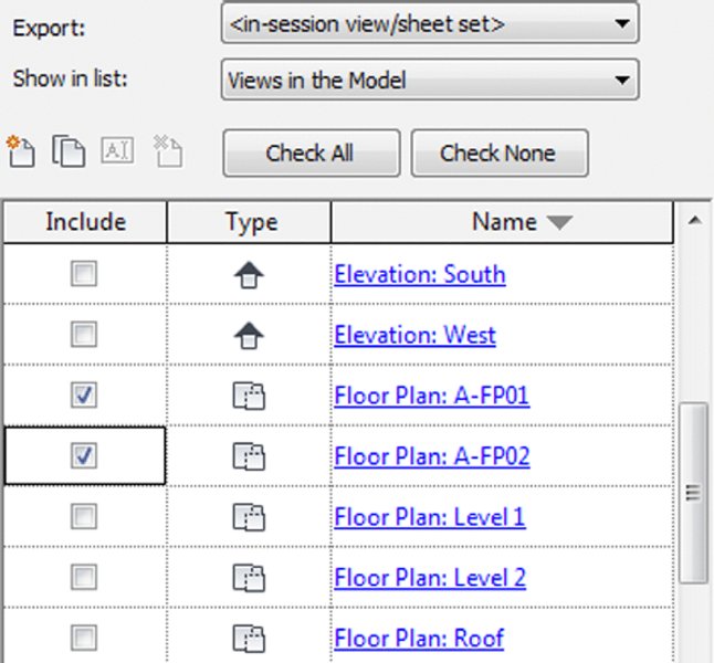
Click the Check None button to clear any extraneously selected views and then find the floor plans with the A- prefix. Select these views by checking the boxes next to the views in the Include column.
Remember, you can sort the list by clicking any of the list headers (Figure 7.20).
For now, we will simply end this exercise by saving the list of views for later. Click the Save Set & Close button and the DWG Export dialog box will close.
Save the project file to continue the next exercise.
Figure 7.20 Adding views/sheets to the export list
Now that you have created a saved list of views for export, they will be available for any CAD export processes. You can create as many lists as you need as well as duplicate, delete, or rename them in the DWG Export dialog box. In the next section, we will show you how to adjust the settings for exported DWG files.
Settings for DWG Exports
In addition to saving lists of views for exporting, you have the ability to save predefined exporting configurations. To complete an export, you will select a list of files and an export setup before defining an export location and launching the process. Let’s examine the various settings that can be customized for DWG export.
Continuing with the c07-Sample-Building.rvt file, go to the Application menu and then choose Export ➢ CAD Formats ➢ DWG. You will return to the DWG Export dialog box. In the previous exercise, you created a named list of views to export. Before we begin an exercise to create a customized configuration for export settings, we will briefly explore the various settings that can be saved and applied to any list of views to complete the export process. Click the ellipsis button at the top of the dialog box. A tooltip will appear showing the associated command as Modify Export Setup. The Modify DWG/DXF Export Setup dialog box will appear (Figure 7.21).
As you can see, a number of opportunities for customization are offered in this dialog box. First, you’ll notice at the left side of the dialog box a list of export setups and icons similar to those found in the main DWG Export dialog box. Use these icons to create, duplicate, rename, or delete export setups in your project. Let’s take a look at some of the other export settings in greater detail.
LAYERS
The Layers tab was shown previously in Figure 7.21. It contains many options to completely customize the export of object styles to layers. Let’s examine each of these settings more closely.
Export Layer Options
At the top of the Layers tab is a drop-down that allows you to specify the overall behavior of exported elements. This setting accounts for any graphic overrides that might be applied in a Revit view. For example, the Linework tool might have been used to modify the edge of a wall to a dashed line. These options determine how that override will be exported to a CAD format.
Export Category Properties BYLAYER And Overrides BYENTITY This option will export unmodified elements to their respective layer assignments, and their properties will remain assigned to the layer. If an object or part of an object has been overridden, the overridden element will still be assigned to the respective layer, but the graphic override will be applied directly to the entity. In the wall example noted previously, the wall edge would still be assigned to the A-WALL layer but would have a DASHED linetype instead of a BYLAYER assignment.
Export All Properties BYLAYER, But Do Not Export Overrides If the recipient of your CAD file will use scripts or macros to enforce their own graphic standards to the exported data, select this option. Using the wall example again, the wall elements would be assigned to the A-WALL layer; however, the dashed line overrides would not be exported. This style of export is usually appropriate for engineers who need to use architectural plans as background information and thus will override all elements to halftone.
Export All Properties BYLAYER, And Create New Layers For Overrides This final option will assign default objects to layers based on their categories; however, any elements with graphic overrides will be assigned to new layers that are subsets of the original layer. Continuing with the previous wall example, the unmodified wall elements will be assigned to the A-WALL layer, but the overridden edge will be assigned to a new layer such as A-WALL-3, where the properties of the element are all BYLAYER and the new layer contains the dashed linetype. In our opinion, this option is less useful because there is no control over the naming of the new layers, thus creating potential confusion for the recipients of the exported files.
Load Layers From Standards
Several exporting templates based on the industry-standard layering guidelines are included (Figure 7.22) with the Revit application and can be applied in the Load Layers From Standards drop-down. Similarly to import settings, you may want to create customized layer export templates and save them with your project data for future reference. Export templates may inherit the layer names of linked CAD files in your active project. Because of this, we recommend saving a copy of your export templates in a Zip archive in case you need to return to the original template.
Figure 7.22 Industry-standard layering conventions can be applied to export settings.
Layer names and colors can also be customized by directly editing the values in the Layers tab in the Modify DWG/DXF Export Setup dialog box. Each category and subcategory is capable of independent color and layer names.
Layer modifiers can be applied to any or all of the model categories for export. To do this, either click in the Layer Modifiers column for any of the listed model categories and then click the Add/Edit button that appears, or click the Add/Edit Modifiers For All button. Either method will open the Add/Edit Layer Modifiers dialog box (Figure 7.23). Here you can assign modifiers such as phase status, workset, view type, or user-customized fields.
Figure 7.23 Modifiers such as Phase Status may be applied to individual or all categories.
LINES
Switch to the Lines tab in the Modify DWG/DXF Export Setup dialog box, and you will find additional settings for assigning Revit line patterns to CAD-based linetypes (Figure 7.24). The first setting at the top of the tab is to assign the linetype scale in the exported CAD files. This option can be configured to Modelspace, Paperspace, or Scaled Linetype Definitions. This setting can be changed by the recipient of the exported files, so it is common to use the Modelspace setting for any model view exports, such as plans or elevations, and the Paperspace setting for sheet views.
Figure 7.24 Line styles can be assigned to specific CAD linetypes.
In the main list within the Lines tab, any line patterns defined in your Revit project can be assigned to a specific CAD-based linetype. The default linetype definitions file is included with Revit, but it can be changed with the command buttons above the line patterns list. The default setting for exporting line patterns is Automatically Generate Linetype, which will replicate the graphic pattern but will not integrate well with any other CAD software if the exported files require additional modification by the recipient.
PATTERNS
As with lines, the exporting of fill patterns can be completely customized. Switch to the Patterns tab (Figure 7.25), and you will see similar options to specify a default CAD-based pattern file as well as the ability to assign Revit fill patterns to hatch patterns that are native to AutoCAD software.
Figure 7.25 Fill patterns can be assigned to CAD hatch patterns.
In Figure 7.25, we have selected a few of the Revit fill patterns to be mapped to a respective pattern from the AutoCAD pattern definition.
Similar customizations can also be made for fonts in the Text & Fonts tab, and in the Colors tab you can choose to either use specific layer-based color IDs or use the true color RGB values assigned in your Revit project. Let’s take a quick look at the remaining tabs and their importance.
SOLIDS
In the Solids tab, you have the option to select either Polymesh or ACIS Solids for exporting of 3D views. For cleaner solid geometry exporting, we recommend the ACIS Solids option; however, this will likely result in larger file size upon export.
UNITS & COORDINATES
One of the most important settings is Coordinate System Basis, which can be found in the Units & Coordinates tab. This option will affect the ability of your exported files to be properly aligned with other project files. Refer back to Chapter 6 for more information on using shared coordinates.
GENERAL
Finally, the General tab (Figure 7.26) contains some additional options such as assignment of non-plottable layers, exporting space boundaries, and default export file options.
Figure 7.26 General options allow further customization of CAD exports.
At this time, you can click the Cancel button to close both active dialog boxes. In the next section, you will return to these settings and save a configuration to be applied to the export process.
Exporting 2D CAD Data
When collaborating with others who require 2D CAD, developing a planned strategy will allow you to share your Revit data more efficiently and consistently. We highly recommend that you determine and document the scope of data to be shared, the schedule by which the files will be shared (when and how often), and the software platforms to be used on a project. These aspects should be compiled in a BIM execution plan, as explained in Chapter 6.
To facilitate the setup and ultimate export of plan data, you can create copies of floor plans and ceiling plans with a standardized naming convention in your Revit project. These should be easy to recognize, and they help in building the export list. Figure 7.27 shows a series of duplicated plans that have been created and assigned to the floor plan type named Export. The view name conforms to the naming convention specified by the United States National CAD Standard (www.nationalcadstandard.org).
Figure 7.27 View organization for plans to be exported
In the following exercise, you will continue to use the c07-Sample-Building-Start.rvt project file while using the saved list of views you created in the “Preparing a List of Views for Exporting” exercise:
From the Application menu, click Export ➢ CAD Formats ➢ DWG. In the DWG Export dialog box, make sure PLANS is selected in the Export drop-down. Click the Modify Export Setup ellipsis button (three dots) at the top of the dialog box.
In the Modify DWG/DXF Export Setup dialog box, select the New Export Setup button from the bottom left to create a new export setup. Name the new export setup British Plans with Phase.
In the Layers tab, set the Export Layer Options drop-down list to Export Category Properties BYLAYER And Overrides BYENTITY. Locate the Load Layers From Standards drop-down list and select British Standard 1192. You will receive an error message stating that loading these settings will replace your previous settings. Click Yes to accept.
While still in the Layers tab, click the Add/Edit Modifiers For All button. In the Add/Edit Layer Modifiers dialog box (Figure 7.28), add the {Phase Status} modifier from the list at the left to the Modifiers Added list at the right. Next to {Multiple Categories} in the Separator column, add a hyphen. The preview above should now read {Multiple Categories}-{Phase Status}. Click OK to close this dialog box.
Switch to the Units & Coordinates tab and set the Coordinate System Basis to Shared by clicking the radio button. Click OK to close the Modify DWG/DXF Export Setup dialog box.
Click the Next button to continue the exporting process. In the Export CAD Formats–Save To Target Folder dialog box, set the Naming drop-down list to Automatic–Short. This will create files named similarly to FloorPlan-A-FP01.dwg.
Uncheck the Export Views On Sheets And Links As External References setting. Although this setting does not affect this exercise, we discuss its importance after the exercise.
Select an appropriate location on your computer or your network for the exported files and then click OK to complete the export process.
Figure 7.28 Add a Phase Status modifier to all categories.
Unfortunately, you cannot customize the naming of the exported files when you export more than one view in a batch process. That said, any kind of file-renaming tool can be used to remove the prefix FloorPlan- from exported files using the Automatic–Short option.
There is one more option that you should understand in the exporting process. In the final Export CAD Formats dialog box, you will see the option to Export Views On Sheets And Links As External References. When this option is checked and you are exporting sheet views, any views that are placed on those sheets will be exported as separate files. Those files will then be configured as external references (Xrefs) in the exported sheets. If you also have other RVT files linked into your current model, they too will be exported as separate CAD files and configured as Xrefs in the exported files.
We recommend that you deselect the External Reference option during exporting unless it is absolutely necessary. The exporting process will result in fewer files and more portable and predictable results for the recipients of your exported data.
Exporting 3D Model Data
In the previous section, we showed you how to export 2D views to CAD formats, which will support more traditional collaboration work flows. You can also export your Revit project as a 3D model in several formats for use in other modeling software. A frequent destination for such data is Autodesk® Navisworks® software for its enhanced coordination with contractors during construction. This workflow is supported by a free Navisworks plug-in to Revit that will allow you to export your models as NWC files, which Navisworks uses. More generic exports in DWG, DGN, DXF, or SAT formats can provide numerous opportunities for you to become more creative with the presentation of your designs.
Exporting to SketchUp
Previously in this chapter we discussed using SketchUp for conceptual building massing studies. These studies were imported directly into the Revit environment for further development of a true building information model. Revit model data can also be exported via 3D DWG to SketchUp, where visualization studies can be conducted on an entire project or even a simple wall section.
In the following exercise, we will export a wall section study from the Revit environment to SketchUp using files you can download from this book’s web page. To complete this exercise, you will need to download SketchUp from www.sketchup.com and install it.
To begin the exercise, follow these steps:
Open the file c07-Sketchup-Wall-Study.rvt.
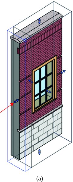
Activate the Default 3D view and enable the Section Box option in the Properties palette for the view.
Set the detail level of the view to Medium or Fine.
Select the section box in the 3D view, and shape handles will appear on each face. Grab the shape handle of one side of the section box parallel to the vertical edge of the wall sample, and drag toward the wall until the section box intersects the wall, as shown in Figure 7.29.
You should see the layers of the wall structure exposed.
With the section box still selected, right-click and choose Hide In View ➢ Elements.
This will prevent the section box from being exported.
Click the Application menu and select Export ➢ CAD Formats ➢ DWG Files. Set the Export drop-down list to <Current View/Sheet Only>.
Click the Modify Export Setup ellipsis button to open the Modify DWG/DXF Export Setup dialog box. In the Modify DWG/DXF Export Setup dialog box, switch to the Solids tab and set the option to Polymesh. Click OK to close the Modify DWG/DXF Export Setup dialog box.
Click Next and set the Files Of Type drop-down to AutoCAD 2013 DWG Files. Select a location on your computer or network, and then click OK to save the file.
Launch SketchUp, and choose File ➢ Import.
Switch the Files Of Type option to AutoCAD Files, navigate to the file saved in step 8, and click Open.
Switch to the Select tool, select the entire DWG import, right-click, and choose Explode.
This will allow you to directly edit the elements in the SketchUp environment. Other components within the exploded model may need to be exploded again.
Figure 7.29 Using the section box to expose the layers of the wall
Once the DWG model is loaded in SketchUp, you can use the Paint Bucket tool to apply materials to individual components, use the Push/Pull tool to hide or expose layers of the wall construction, and use the line tools to customize the profile of the revealed layers, as shown in Figure 7.30.
Industry Foundation Classes (IFC) are the data model standard developed by buildingSMART International to support interoperability in the building industry. The IFC model specification is registered by the International Standards Organization (ISO) as ISO/PAS 16739 and is currently in the process of becoming the official International Standard ISO/IS 16739. Because of its focus on ease of interoperability between BIM software platforms, some government agencies are requiring IFC format deliverables for publicly funded building projects.
Some scenarios where IFC exchange may apply and facilitate data exchange include, but are not limited to, the following:
Linking AutoCAD MEP software into a Revit project
Using Solibri Model Checker or Viewer for model quality audits
Coordination between Revit projects and Nemetschek Allplan, Vectorworks, or ArchiCAD
AutoCodes Project by Fiatech
COBie (Construction-Operations Building Information Exchange) deliverables
GSA spatial validation
You can export the Revit model quite effectively to the IFC 2×2, 2×3, BCA ePlan Check, or IFC GSA 2010 formats by clicking the Application menu and selecting Export ➢ IFC. The resulting IFC file (Figure 7.31) can be viewed in a number of programs that can be downloaded at no cost from any of the following websites:
DDS-CAD Open BIM Viewer from Data Design System (www.dds-cad.net)
Importing IFC data into the Revit environment is similar to the process for importing 3D CAD geometry; however, the data generated is intended to be more intelligent and editable. Although this method has great potential, the accuracy of the Revit IFC import is highly dependent on the software used to generate the IFC output. We recommend the use of one of the free IFC viewers listed previously to inspect IFC data prior to importing into a Revit project.
After you’ve reviewed the contents of the IFC file, you can link it into a Revit project and integrate it into your coordination process as follows:
Start a new project with any default template. From the Insert tab in the ribbon, click on Link IFC.
Navigate to the c07-Structure.ifc file and click Open.
Save the project file.
Open the default 3D view and inspect the linked geometry.
If an updated IFC file is received, overwrite the linked file you used in the previous steps. When the host project file is reopened, the linked IFC content will be updated.
DOWNLOADING AND CUSTOMIZING THE OPEN SOURCE IFC EXPORTER
In addition to offering a basic IFC export command in the default installation of Revit, Autodesk has been developing an improved IFC exporter on the website SourceForge.net (http://sourceforge.net/projects/ifcexporter). Anyone can download the source code for this exporter and contribute to its development. This allows a larger international community to provide input on the improvement of this important feature.
The open source exporter consists of two separate downloads and installations: the exporter and a custom export UI. After they are installed, you can still launch the IFC export command from the Application menu; however, you will see a new IFC Export dialog box (Figure 7.32). Much like the CAD export process we described earlier in this chapter, this interface allows you to create, customize, and save export setups.
Figure 7.32 The open source IFC exporter user interface
In the IFC Export dialog box, click the ellipsis button next to the Current Selected Setup drop-down list and you will be able to customize the IFC export setup (Figure 7.33). In addition to the predefined export configurations, you can create and save your own setups that will be maintained in the Revit project file.
An excellent resource for IFC interoperability in Revit is the buildingSMART alliance web page for Common Building Information Model Files (www.nibs.org/?page=bsa_commonbimfiles). You can download sample files as well as a configuration guide with additional instructions related to customizing IFC exports from Revit.
CLASSIFYING IFC EXPORT SETTINGS
Because exporting to IFC format is about converting one model format to another, settings are not related to layer conversions, linetypes, or text, as they are in a CAD export. Rather, it is critical to correctly map the logic of the Revit model organization to the open data standard. In other words, model object categories must be mapped to IFC entities; for example, walls in Revit will be exported as IfcWall entities. This translation seems quite logical for walls and other objects, but consider an electric receptacle. Such a device would be categorized in Revit as an Electrical Fixture; however, it is classified as IfcFlowTerminal in the open standard. Entities are further refined with types—in this case, IfcFlowTerminalType—that would help distinguish an electric receptacle from other IfcFlowTerminal entities such as a faucet or an air diffuser.
The schema of the currently released standard (IFC4) can be viewed at www.buildingsmart-tech.org, the portal for the Model Support Group and Implementation Support Group. Although IFC4 is the currently released standard, many workflows still use IFC2x3, including native export from Revit software. If you work with IFC export and import regularly in the Revit environment, you should become familiar with some of the common classifications in the IFC schema. You’ll find the IFC2x3 IFC4 schema indexes here:
Click Alphabetical Listing and then Entities, and you will be able to browse through some of the most common IFC classifications related to building elements. For example, find and click IfcCovering, and you will see that this classification is used for wall claddings, flooring, and suspended ceilings.
One aspect of the Revit project model that can be exported to IFC is a structural grid. These datum objects are beneficial to the coordination process if you are using Solibri Model Checker or Viewer or Tekla BIMsight; however, they are not exported if you use the default IFC export settings in Revit. Let’s solve that problem with a quick exercise. You can continue to use the c07-Sample-Building-Start.rvt file.
From the Application menu, click Export ➢ Options ➢ IFC Options.
You might need to scroll down the Export menu to see the Options flyout.
In the IFC Export Classes dialog box (Figure 7.34), find the entry for Grids and set the IFC Class Name to IfcGrid. You must manually enter any IFC entities and types into this dialog box; therefore, you should always refer to the buildingSMART website for accurate classifications.
Click OK to close the IFC Export Classes dialog box.
You can save the IFC mappings to a text file for use in other projects.
From the Application menu, click Export ➢ IFC. If you are not using the custom IFC exporter that we discussed earlier in this chapter, simply set the export file type to IFC2×3 and save the file to your computer or network.
Open the IFC file in an application such as Solibri Model Checker or Viewer, and you will be able to see the Revit grid lines in the model-only exported format.
Figure 7.34 Customize the mapping of Revit categories to IFC entities.
There are two other methods to customize the classification mappings for IFC. One is to use subcategories in families. As an example, a Revit family created for an elevator has been assigned to the Generic Models category; however, a subcategory named Elevators was created in the family (Figure 7.35).
Figure 7.35 Create subcategories in a family for customized classification.
After the elevator family is loaded into a project, the new subcategories can be assigned to an appropriate IFC classification. Click the Application menu, and then click Export ➢ Options ➢ IFC Options to open the IFC Export Classes dialog box. Locate the Revit category for Generic Models and you will also see the Elevators subcategory, as shown in Figure 7.36. For IFC Class Name, enter IfcTransportElement and for Type, enter IfcTransportElementType, and you will be ready to export your project with the additional object classifications.
Figure 7.36 Subcategories can be mapped directly to IFC classifications.
The second method of classification customization is to use two specific shared parameters associated with a family. These parameters must be named IfcExportAs and IfcExportType, as shown in Figure 7.37, but they can simply be selected from a shared parameters file downloaded from the Common BIM Files web page mentioned previously in this chapter. When these families are loaded into and placed in a project, the IFC classifications will be automatically mapped according to the values specified in these parameters.
Figure 7.37 Use specific shared parameters to customize IFC mapping.
The Bottom Line
Use imported 2D CAD data. CAD data can be integrated into your Revit project in a number of ways: as plans of existing conditions, as fixture layouts from consultants, or as standard details from your company’s library.
Master It How can CAD details be used in a Revit project?
Export 2D CAD data. The ability to deliver quality 2D information to other constituents involved in your project is as important as importing it into the Revit environment. Appropriately formatted views, standardized layer templates, and proper coordinate settings will result in happy team members and a smooth coordination process.
Master It Does Revit software comply with the National CAD Standard?
Use imported 3D model data. Model data generated outside of the Revit environment can be integrated into your projects as whole-building systems, massing studies, or unique components.
Master It How can a building’s structural model created with the Bentley Structure be integrated into a Revit project?
Export 3D model data. Your modeled elements don’t have to remain in the Revit environment forever. Data can be exported to 3ds Max, SketchUp, AutoCAD MEP, and more.
Master It How can you coordinate your architectural Revit model with an engineer using AutoCAD MEP?
Work with IFC imports and exports. Industry Foundation Classes (IFC) is a vendor-neutral model format designed to support interoperability in the AEC industry. It is widely used by some major BIM platforms available around the world.
Master It How is an IFC model integrated into a Revit project for coordination?