
Chapter 18
Annotating Your Design
No set of documents is complete without the annotations to describe the drawings. Even when you are using a digital, parametric model, you still need to provide annotated documents. It is necessary to add dimensions, tags, text, and notes to the drawings to properly communicate with owners, contractors, and the rest of the design team.
In this chapter, you’ll learn to:
- Annotate with text and keynotes
- Use tags
- Add dimensions
- Set project and shared parameters
Annotating with Text and Keynotes
Notes are a critical part of communicating design and construction intent to owners and builders. No drawing set is complete without descriptions of materials and the work like the ones you can see in Figure 18.1.

Figure 18.1 An annotated detail
There are two ways to add notes to your drawings in Autodesk® Revit® Architecture software. Both are located on the Annotate tab and highlighted in Figure 18.2. One of these methods is the Text command (shown on the left), and the other is the Keynote command (shown on the right).

Figure 18.2 The Text and Keynote commands
The text object consists of a resizable field into which you can enter text with optional features, including leaders, bullets, or numbers. Text can be used for annotations, sheet notes (such as general notes), or legends; it can be used generally anywhere you need to add a description or a note.
Keynotes are predefined text fields that are linked to elements and materials through a data file. Keynotes can be scheduled and standardized across the project but can’t be directly edited within the application. Both keynotes and text have specific uses. Let’s look at how both of these can be used in a project.
Using Text
Text is quick and easy to add to any view (including 3D views), and like other drafting elements it is view-specific. Text added to one view will not appear in any other location within the model, nor will the information that you insert into the text box hold any sort of parametric values.
You can access the Text tool from the Text panel on the Annotate tab (shown previously in Figure 18.2). To begin adding text, select the Text tool and first observe the settings in the contextual ribbon. You can specify an option for a leader, the position of the leader, and the justification of the text. It is easier to set these options before you place a text object, but they can always be adjusted later.
After you have selected the most appropriate settings for your annotation, go to a place in a view where you’d like to place the text object. You will have the opportunity to use one of two methods to create the text object. If you click once, the location you clicked will be the origin of the text object and the text will not have a defined width. Using this method, you may need to use the Enter key to fit the text to your needs—pressing Enter will create a line break in the text box. This method may cause some difficulty in the future if you need to resize the text box or if you change the scale of the view.
The other option is to hold down the left mouse button while you click to place the origin of the text. Then drag the mouse pointer to specify the boundary of the text object, creating a box. Don’t worry about the vertical extents of the boundary; you just need to set the width of the text box. Using this option gives you greater flexibility if you need to resize the text box or if the scale of your view changes, because the word-wrapping will be handled automatically. With the Text command active, you’ll be presented with the standard mouse pointer crosshair, but it will have a small A in the lower right corner to let you know you are adding text and not other elements. In either case, if you need to adjust the width of your text box, you can do so at any time using the grips.
If you select one of the leader options in the ribbon before placing the text object, your first one or two clicks (depending on the leader option selected) will be to place the leader. For example, if you choose the two-segment line leader option, your first click will be the arrowhead of the leader. Your second click will be the elbow of the leader, and then the third click will be the beginning of the text box. At this third click, you can still drag the mouse pointer to predefine the width of the text box. Try this a few times until you become familiar with the implicit placement and snapping alignment of text objects and leaders.
Once you place a text object in a view, you can write much as you do in applications such as Microsoft Word. Once you finish typing, click outside the text box. Your finished text box will look like Figure 18.3.

Figure 18.3 A highlighted text box
You’ll also notice that once you finish with your initial text or you select an existing text object, a few tools are available with which you can modify the text:
Grips The round grips on either side of the text box allow you to resize the width of the box.
Move There is a move icon that appears in the upper-left corner of the text box. In addition, hovering your mouse anywhere within the highlighted text will also display a move cursor. You can click and drag from within the box or click the move icon on the upper-left corner to relocate it. When you’re moving text with the move icon (or the Move command), the text and leader will relocate together. When you’re moving text by dragging, the leader end will remain pinned while you relocate the text box. These methods let you move either the text or the text and the leader, depending on your need.
Rotate The upper-right corner shows a rotate icon. Clicking this icon allows you to rotate the text box as you would any object in a project. Remember that text will always position itself to be read left to right if it is horizontal or bottom to top if it is vertical in a view.
A text family behaves like other families because it maintains a parametric relationship throughout the project. Making type property changes to a text object in one location (changing font, font size, color, and so on) changes all the instances of that type throughout the model. To modify text type properties, select a block of text or choose the Text tool and then observe the Properties palette, as shown in Figure 18.4.

Figure 18.4 Type Selector for text
The instance properties for text objects are rather limited and deal primarily with controls such as alignment, location, and so on, which you can also set on the ribbon. The Type Selector also allows you to select a different text type or edit the properties of the currently selected type. Click the Edit Type button to open the text family’s type properties. Figure 18.5 shows the properties for the default 1/4″ Arial text type.

Figure 18.5 Type Properties dialog box
In the Type Properties dialog box, you have more control over the style of the text. Here you can modify typical text properties, such as font, size, and width factor. You can also add formatting to the text, such as bold, italic, and underline. Other important settings to consider include Show Border, Background, and Leader Arrowhead. The Show Border property simply allows all text object instances to be enclosed with a line boundary. The Background property can be set to either Opaque or Transparent, which will control whether the text will obscure objects beneath it. Finally, the style of leader arrowhead is defined in the text type properties to help you maintain consistency throughout your design documents.
CONTEXTUAL TEXT FORMATTING
![]() When any text object is selected in a view, additional formatting tools become available on the ribbon. The Format panel is divided into four sections that allow you to modify the instance of the text you’ve placed. Figure 18.6 shows the Format panel when the overall text object is selected and when you activate the text within the object. Let’s look at this panel in more detail to better understand the toolset:
When any text object is selected in a view, additional formatting tools become available on the ribbon. The Format panel is divided into four sections that allow you to modify the instance of the text you’ve placed. Figure 18.6 shows the Format panel when the overall text object is selected and when you activate the text within the object. Let’s look at this panel in more detail to better understand the toolset:


Figure 18.6 The Format panel in the contextual tab of the ribbon when placing text (a); selecting a text object (b); and editing text within the object (c)
Leaders The leftmost section of this panel (A) allows you to designate the type and style of leader you want to add to your text box. When you activate the Text tool, the upper-left A is selected by default (as in Figure 18.6), which designates that no leader is currently added. The other choices all add a leader to the text. Reading from left to right, the options are no leader, a single-segment leader, a double-segment leader, and an arc leader. Leaders can be added at any time when you’re placing or editing text and can also be removed at any time. Remember that when you’re removing leaders, they will disappear in the order in which they were added.
Leader Location The second portion of this panel (B) dictates leader location. Leaders can be added to the left or to the right and at the top, middle, or bottom of the text box. The top example in Figure 18.7 shows the default with a left leader springing from the upper left of the text; leaders that spring from the right side typically come from the end of the text box (at the bottom). A double-segment leader springing from the left and right will look like the example shown in Figure 18.7.
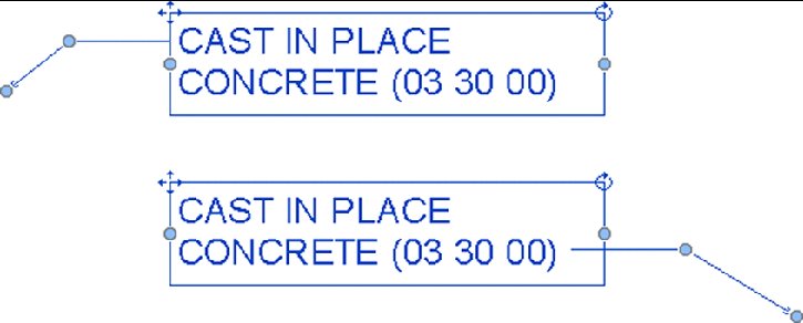
Figure 18.7 Text with leaders attached to different sides
Format The third portion of the Format panel (C) controls the format of the text. These features—align, bold, italicized, and underline—can also be added to the type properties of the text family by clicking Edit Type in the Properties palette; however, you can add them to individual text within a text object by using the contextual ribbon.
Bullets The rightmost portion of the Format panel allows you to add a formatted list to the text box. By default, this style of formatting is not added, but by selecting the text box or the text within the box, you can add bulleted, numbered, or alphabetical lists to the text.
Using Keynotes
Keynotes are annotations that use a parameter to connect specific elements or materials in the model to descriptive information stored in an external TXT file. You can control the formatting of the keynote’s font style, size, and justification in the same manner as you can format standard text, but keynotes are essentially a tag family. Formatting changes must be made in the keynote’s family (RFA) file and reloaded into the project.
Inserting a keynote allows you to choose a value from the TXT file and apply it to a material or element. Because keynotes act as families, they can also be scheduled where standard text cannot. Before we discuss how to add different keynote types, we’ll explore the various ways a keynote can be displayed.
Without official corroboration from Autodesk, it appears that the keynoting functionality was designed to support the American Institute of Architects (AIA) proposal of the ConDoc system, in which a short numeric reference (usually based on MasterFormat by the Construction Specifications Institute) followed by a two-letter suffix is used to label elements in a drawing. The keynote then references a list or legend that is located on the same sheet as the note and has a longer definition of the note. For example, a keynote on a detail might read 033000.AA, with a leader pointing to an element in the drawing. The associated list on the side of the sheet would read CAST IN PLACE CONCRETE. Figure 18.8 shows an example of a keynote legend.

Figure 18.8 A keynote legend
Despite the intended use of a keynote, you are not restricted to using only the numeric code. You can also display the full, written description directly within the detail or view without the numeric reference key. Figure 18.9 shows an example of keynotes that display the full description instead of the key.
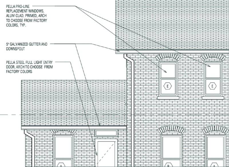
Figure 18.9 Keynotes displaying full text descriptions
There is no wrong way to use keynotes, and Revit supports both methods of using them for annotation. Regardless of the method you use, keynotes will adhere to the same process for use. Once an element is tagged with a keynote, it will retain that keynote in all other views in the model. If an element has been tagged with a keynote in one view and is then annotated in another view, it will automatically display the same keynote value. This can become a powerful tool you can use to add consistency throughout the project for annotated elements.
The Keynote command is located on the Annotate tab in the ribbon. When you select the Keynote tool, you have three options:
Element Use Element keynotes to annotate elements and assemblies within the model, such as walls, doors, floors, or other family instances. This type of note is typically used if you want to annotate an entire assembly (such as a wall, roof, or door). Moving the Element keynote leader arrow off the object will change the value of the note based on the element to which it points. The keynote value for a family type can be preset within the family. We’ll go into that later in this chapter.
Material Using the Material keynote type will allow you to annotate specific materials within any elements. You can add notes for materials like concrete, gypsum board, rigid insulation, metal studs, and so on. Moving the Material keynote leader arrow from one material to another will change the value of the note based on the material to which it points even if it’s within the same element. So, a wall with multiple materials can have several Material keynotes. Material keynotes can also be predefined as part of your project template through the Materials tool on the Manage tab. Material keynotes can also be used in conjunction with Element keynotes (Figure 18.10).

Figure 18.10 Adding a Keynote value to the identity data for a material
User User keynotes are different from Element and Material keynotes because they are view-specific and cannot be predefined. Although they are still tied to the same TXT file and will update in the same manner as other keynotes, they are not associated with any model objects. User keynotes are meant to be used for all the instances when you don’t have a modeled element or material but you still need to define a note. Some examples of things you wouldn’t necessarily model might be sealant, backer rod, or flashing.
User keynotes are used primarily in drafting views. To use any keynote, a given view must have at least one model element or component visible within it. In the case of a drafting view, you will need to insert a 2D component (such as wood blocking or a steel stud) because keynotes cannot be used to note linework. Because User keynotes are not locked to specific model geometry, once they are inserted they can easily be copied or moved around within the view and pointed toward any element. In this way, if you have sealant or flashing shown as linework, you can add a User keynote to the view and then adjust the note leader and the note value to call out the sealant properly. You can change the value of a User keynote at any time simply by double-clicking the note value; this modification will not affect any other notes within the project.
You can use all of these note types in conjunction with one another. Using an Element note to add a keynote to a wall doesn’t mean you cannot also use a Material note to call out the individual materials in the wall assembly.
ASSIGNING KEYNOTES AND EDITING
A core concept of the Keynote tool is how the notes react within the model. Assigning a keynote to an object lets you associate a text or numeric value with a family’s keynote type parameter. This value is consistent for every instance of that element within the model or project. For example, all walls have a type parameter called Keynote that lets you set the keynote value. If you keynote a wall anywhere within the model, the keynote value in the type parameter will reflect that note. Consequently, any other wall of that type will be prepopulated with that keynote value. Changes to this keynote value will dynamically update the type parameter value and update any keynotes placed within the model tagged to this wall.
All keynotes within a project are tied to an external TXT file. This TXT file is the only location where the value of the keynotes can be edited. You can modify this file at any point to add or remove notes, and you can make the edits while the project is actively open. Figure 18.11 shows a sample of the file.

Figure 18.11 The keynote TXT file
This external file is designed to keep the annotations consistent by storing them in one repository. Every time you add or change a note value and reload the TXT file back into the Revit model, all the keynotes dynamically update.
You can edit this TXT file or add one to the project at any time. You can have multiple keynote files for various projects, but you can have only one TXT file associated with a project at a time. You cannot assign multiple keynote files to one project model.
Because the keynote list is a separate TXT file, if you are transferring files to other offices or clients, you may need to include the TXT file along with the RVT file. If you don’t send the TXT file, others will be able to see all your keynotes but they won’t be able to change or edit any of them.
USING THE KEYNOTE FILE
Three default keynote text files are available at the library locations. In Windows 7 or Windows 8, they are found at C:ProgramDataAutodeskRVT 2016LibrariesUS Imperial (there is also a default keynote file in the Metric folder). Another way to find these files is to start a new project using the default template and go to the Annotate tab. Click the Keynote drop-down arrow on the Tag panel and select Keynoting Settings. In the Keynoting Settings dialog box, click the Browse button and you will be taken to the default library location.
These four keynote files are called RevitKeynotes_Imperial.txt, RevitKeynotes_Imperial_2004.txt, RevitKeynotes_Imperial_2010.txt, and RevitKeynotes_Metric.txt. You can edit any of these files in Notepad or Excel and follow the format already established within the file. Let’s look at the format of this file so you can understand how to customize the keynotes.
The first few rows of the file (Figure 18.12) designate the grouping of the notes. In this example, they consist of a label (Division 03) followed by a tab and then a description (Concrete).

Figure 18.12 The keynote TXT file header
Directly below this header is a secondary, or minor, grouping. This secondary grouping follows the same format as the primary group and provides better control over how the keynotes are displayed within Revit. This line follows the same format as the first: Label (033000), then a tab, then a description (Concrete), then another tab, and then a reference to the parent code (Division 03). This last entry must match the label in the line above. This designates the second line as a subset to the first line. You can add as many or as few subgroups as you’d like. In our case, we have subcategories for each division, but that’s not necessary.
Below the grouping are the contents of that group. These lines are articulated in the following format:
In the example shown in Figure 18.12, this reads as follows (where the [tab] is an actual tab, not the text):
To get an idea of how this will all look once loaded into Revit, Figure 18.13 shows you the Keynotes dialog box with Division 03 expanded.

Figure 18.13 The Keynotes dialog box
Using the keynote file approach lets you add, remove, or edit notes and groups of notes. It might seem frustrating to have to open and load a separate TXT file every time you want to add or remove notes from the keynote list. However, remember that this also maintains consistency and a level of control over the master list that isn’t available with simple text objects. Although it might be slow at stages to get all the project notes into the TXT file, it also means that the time you’ll spend checking and verifying the notes is dramatically reduced.
If you find that editing keynotes in an external TXT file that is segregated from the project environment does not suit your needs, tools are available online to help you manage keynotes using a graphical interface. Revolution Design has created a tool called Keynote Manager (www.revolutiondesign.biz) that will manage your keynote list, create headings and subheadings, and format the TXT file in a way that Revit can read it. Tools like this are great for speeding up the editing process for keynotes and maintaining proper formatting of the TXT file.
ACCESSING KEYNOTE SETTINGS AND LOADING THE TXT FILE
Now that the keynote TXT file is established and you’ve begun populating it with annotations, you need to link it to your project. Loading this file into the project is simple and needs to happen only once. Additionally, loading this keynote file is a project setting, not a user setting. Once the file is linked, all team members will have access to the keynotes. As a side note, if you are working in a team environment, make sure to place the keynote file in a location everyone has access to, like a network resource. Placing it on your C: drive will allow you access to it but will not allow others on your team to see the notes.
To access the keynote settings and load the keynote text file, go to the Annotate tab in the ribbon, locate the Tag panel, and then click Keynote ➢ Keynoting Settings, as shown in Figure 18.14.

Figure 18.14 Accessing the Keynoting Settings
This command will open the Keynoting Settings dialog box (Figure 18.15). Here, you can define the project’s keynote file as well as adjust some other settings. To load the keynote file, click the Browse button and navigate to the TXT file you created.

Figure 18.15 The Keynoting Settings dialog box
Here are some other variables that you can set in the Keynoting Settings dialog box:
File Path File Path defines how Revit Architecture looks for your text file using one of three methods:
Absolute The Absolute option follows the UNC naming conventions and navigates across your network or workstation for a specified location.
Relative This option locates the text file relative to your RVT project file. If you move the RVT file and the text file and maintain the same folder structure, the keynote file will be found and automatically loaded.
At Library Locations This option lets you put the text file in the default library location defined in the File Locations tab of the Options dialog box (Application ➢ Options).
Numbering Method Numbering Method defines how the keynotes are numbered:
By Keynote This option allows you to number keynotes as they come from the associated text file.
By Sheet With this option enabled, the keynotes are numbered sequentially on a per-sheet basis.
ADDING KEYNOTES
Download the project file c18-Sample-Building-Start.rvt and the keynote file MARA_Keynotes.txt from the folder for Chapter 18 on this book’s web page at www.sybex.com/go/masteringrevitarch2016. Make sure you place them in the same folder on your computer because the path setting for the keynote file is set to Relative in the RVT file. Open the RVT project file to begin the exercise.
To add keynotes to an element in a project model, choose one of the three keynote types from the Annotate tab; then select the object you want to annotate in your view and insert a keynote. The sequence for inserting keynotes is arrowhead, leader segment, and then keynote. Similar to placing a tag, the Keynote command (even the User keynote) requires an object to be selected to start the insertion sequence. If the object doesn’t have a note already defined, you’ll be prompted to pick a note from the Keynotes dialog box. Figure 18.16 shows a sample of this list.

Figure 18.16 Choosing a keynote to insert
Let’s explore this functionality with a quick exercise in which you will annotate a detail with keynotes. Follow these steps:
- From the Project Browser, expand the Sections (Wall Section) heading and activate the view named Window Sill Detail.
- Go to the Annotate tab in the ribbon and select Keynote ➢ Element Keynote on the Tag panel.
-
Select the window in the view and then place the leader and keynote.
You will see that the keynote code has already been populated because the keynote has already been defined in the type properties for the window family.
- With the Element Keynote command still active, click the wood sill detail component and place another keynote. This time, the Keynotes dialog box will appear because no keynote was defined in the wall’s type properties. Select the keynote labeled 061100.AA and then close the dialog box.
- Go back to the Annotate tab in the ribbon and select Keynote ➢ Material Keynote.
- Select the cross-hatched material at the right side of the wall below the window. Again, the Keynotes dialog box will appear because a keynote value was not defined in that material’s identity data. Select the keynote labeled 071300.AA and then close the dialog box.
The results will look like the image in Figure 18.17.

Figure 18.17 A section detail with keynotes applied
CREATING KEYNOTE LEGENDS
Depending on your choice of keynote and your workflow, you might want to create a legend on each sheet for your notes. You might want only the keynotes that are shown on a given sheet to appear in the legend. Or you might want to have one legend that will show all keynotes used throughout the project.
These legends usually reside on the side of a sheet near the title block information and can take one of two forms. The first type is all-inclusive and shows every note within the project. This style has the benefit of consistency between sheets in the set. The same note will always be in the same location in the list; however, this type of list can become quite long for larger projects. The other type of keynote list includes only the notes that show up on a particular sheet. This has the advantage of supplying a list of notes customized for each sheet without extraneous information. Creating either list manually has traditionally been challenging. One of the benefits of Revit Architecture is the ability to completely automate either list type, thus removing much of the chance for error in the process. Let’s review how to create both types of lists.
Creating a keynote legend is simple: Choose the Legends button on the View tab and select Keynote Legend from the drop-down list (Figure 18.18). Once you launch the command, name the keynote legend, and then click OK.

Figure 18.18 The Keynote Legend button
You’ll be presented with what looks like a typical schedule dialog box, called Keynote Legend Properties. There are only two fields available in a keynote legend, and by default, they are both loaded into the Scheduled Fields side of the Fields tab (Figure 18.19). Those fields are as follows:

Figure 18.19 The Fields tab of the Keynote Legend Properties dialog box
Key Value This field contains the numeric value of the keynote.
Keynote Text This field contains the text description for the keynote.
A keynote legend works like any other schedule as far as formatting and appearance go. By default, the sorting and grouping are already established because the key value is used to sort. The one special item of note is located on the Filter tab. At the bottom of this tab is a feature unique to this type of schedule: a Filter By Sheet check box (Figure 18.20). Selecting this box gives you the ability to filter the list specifically for each sheet set; leaving the box deselected will supply a full list of the keynotes over the entire project.

Figure 18.20 The Filter By Sheet option on the Filter tab in the Keynote Legend Properties dialog box
Like any other type of legend, a keynote legend can be placed on sheets again and again within the project. You’re not limited to only one instance of the legend on a sheet as you are with other view types. Additionally, if you choose the keynote legend that filters by sheet, it will dynamically modify the note list based on individual sheet contents. As views are added or removed from a sheet or notes are added to the project, the keynote legend updates accordingly.
Keynote legends are considered to be another type of legend view and will appear under the Legends node of the Project Browser.
USING THE KEYNOTE FAMILY
Revit Architecture comes with a default keynote family that allows you to produce both keynotes and text notes using the default keynote TXT file. The family name is Keynote Tag.rfa. This family has four types that let you change note styles within the project, as Figure 18.21 shows.

Figure 18.21 Keynote styles available in the default tag
Here are the four default styles:
- Keynote Number
- Keynote Number – Boxed – Large
- Keynote Number – Boxed – Small
- Keynote Text
Each of these tag types pulls information from the text file we discussed previously in this chapter and reports it at the end of the leader. To change your keynotes between any of these options, select the keynote and choose a different type in the Type Selector.
Annotating with Tags
Tags are text labels for elements such as doors, walls, windows, rooms, and several other objects that architects typically need to reference in a set of drawings. In Revit Architecture, tags are intelligent, bidirectional graphics that report information stored in an object’s properties. Once you’ve tagged an element and entered a value in the tag, the tagged model element will retain that value until you remove it. The value lives with the model elements in a project; it is not a property of the tag. That means you can delete or remove tags without fear of losing the data entered into the tag. It also means that once an element is tagged with information in one view, if the tag is configured to report a type property, the same or similar elements will report the same information in any other view in which they are tagged without the necessity of entering the information twice. To explain this a bit better, take the example of a wall tag.
You’ve placed a wall tag in a view. The tag initially had “?” as a value, meaning that the Type Mark property for that wall was blank. In the wall tag, you’ve entered a wall type value of A1. In another view, you can now tag the same wall type and it will automatically display a value of A1. You can also delete any, or even all, of the tags for that wall, and new tags you place will still report the type number of A1.

Keep in mind that you can also tag elements that are in linked models. Although you cannot edit the properties of these elements (for example, you cannot change the wall type or door number), you can add tags to any of the linked elements as if the same elements were part of your project file.
Tags are versatile elements for annotating your designs. A tag can display a door number, but it can just as easily display any other properties of the door, such as fire rating, cost, or material type.
Inserting Tags
Tags can be automatically inserted when a model element, such as a door or room, is placed within the project (by checking the Tag On Placement option in the contextual tab of the ribbon), or they can be inserted later. The options to place a tag are all located on the Tag panel of the Annotate tab (Figure 18.22).

Figure 18.22 Tag tools in the Annotate tab
When you’re adding tags, it’s not necessary to find or choose the right tag—they will be assigned automatically. Tag families are specific to the elements to which they are being tagged. For example, you use a door tag to tag a door, but you can’t use a door tag to tag a wall or other element within the project. Figure 18.23 shows you some of the tags that are available; there is a tag for each type of object. You can customize each of the tag family types so you can graphically differentiate your door tags from wall tags, room tags, area tags, and so on.

Figure 18.23 Listing of various tag families
When inserting a tag, you’ll have several placement options available in the Options bar, as shown in Figure 18.24.

Figure 18.24 The Options bar when placing a tag
Orientation The first option allows you to orient the tag horizontally or vertically. Tags, like text, will always read from either the bottom or right side of the sheet or view.
The Tags Button Clicking this button opens the Loaded Tags and Symbols dialog box, where you can load various tags.
Leader The final three options relate to the tag leader. You can select the Leader check box (or turn it off) to have a leader show (or not show). Although attached leaders are the default for tags, the Leader drop-down can be changed from Attached End to Free End if you don’t want to associate the end of the leader with the element you’ve selected. Using the Free End option allows the leader to float free of the object. The final option of this set for leaders is the default leader length. By default, the value is set to 1/2″ (12 mm). When you’re placing tags like wall tags that have leaders perpendicular to the wall they are tagging, it is a good idea to set a default length with which you are comfortable. You can adjust the tag location after inserting them, but sometimes it’s easier to set a good default value in leader length.
 Using the Tag Toolset
On the Annotate tab, you’ll find several tools that you can use to insert tags. Look back at Figure 18.22 to see these tools. Each has a different purpose and can be used in conjunction with other tools or separately to help document your project. Let’s take a look at each one:
 Tag By Category The Tag By Category button is possibly one of the most frequently used Tag commands. As we mentioned before, several tags are available, allowing you to tag a host of elements in the model. Click the Tag By Category button when you want to tag one element at a time, regardless of its category.
Using this tag command will allow you to select a door, a window, a wall—whatever single element you want to apply a tag to in the model. As you hover over elements, the tag type that corresponds to that element will be shown. Should the element you are trying to tag not have the associated tag loaded in the project, you will be prompted to load it (Figure 18.25).

Figure 18.25 Loading a tag for a specific element type
 Tag All The Tag All button, which activates the Tag All Not Tagged command, will do exactly that: tag all the untagged elements of a selected category within a given view. For example, you can tag all the doors. Or you can tag all doors, walls, and rooms—or any combination of any list of elements. When you select the Tag All command, the Tag All Not Tagged dialog box will appear (Figure 18.26). This dialog box displays a list of the elements in the view for which you have already loaded tags. Here, you can specify which elements can get tagged, what tag will be used, and if that tag will have a leader assigned to it. Use the Ctrl key on your keyboard to select more than one element from the list. When you’ve selected the categories you would like tagged, click OK.

Figure 18.26 Tag All Not Tagged dialog box
Tagging all the elements within a view can be a wonderful time-saver—but only if you’re okay with the software choosing the location for each of the tags. For example, the tags will be placed in the middle of the rooms. For most spaces, that will work just fine. For other tag types, such as walls or doors, you might have to adjust tag locations to make sure everything reads properly.
Room Tag and Area Tag These two tag types work in much the same way. They will tag the room elements or area elements, depending on the type of view in which you happen to be. In other words, Room tags will work only in plans and elevations, whereas Area tags can be placed only in area plans. To tag rooms or areas, simply select the tag type you want and select the room or area object. When you place rooms or areas initially, the tag option is selected by default.
Material Tag The Material tag is used to annotate specific materials within a model element, similar to the Material keynote. The main difference from the keynote is that the tag does not use an external TXT file to read additional information about the tagged element. The default Material tag will display the Material Description value (Figure 18.27, left) as opposed to the Keynote value. You can always customize the Material tag to display other values such as the Mark, as shown in Figure 18.27 (right).

Figure 18.27 Two options for tagging materials
Multi-Category Tag The Multi-Category tag allows you to use the same tag style in a project to tag elements of different categories. This tag type can be useful in a number of ways. Let’s say you want to tag several elements in a floor plan and call out their manufacturer and unit cost. Typically, you would have to create a few different tag families to tag furniture, casework, lighting, and so on. Now a single tag type can do this for you by tagging the same field (like manufacturer or unit cost) across different element types. Let’s step through making a Multi-Category tag.
From the book’s web page, download the c18-Sample-Building-Start.rvt or c18-Sample-Metric-Start.rvt file or continue with the exercise file from the previous section. Then follow these steps:
- Activate the Level 1 floor plan.
- Click the Application menu and choose New ➢ Family. This will take you to the default family templates. Open the
Annotationsfolder and chooseMulti-Category Tag.rftorMetric Multi-Category Tag.rft. - In the Family Editor, go to the Create tab and select the Label tool. Click near the intersection of the reference planes in the view to place a label.
- Once the label is placed in the view, the Edit Label dialog box opens (Figure 18.28). Here you’ll see a list of the parameters that are common across multiple family types—Assembly Code, Cost, Family Name, and Model, among others. Select Manufacturer and Cost from the list and click the icon with the green arrow to add them to the Label Parameters list. Make sure the Manufacturer parameter is above the Cost parameter (you can do this by selecting Manufacturer and then the Move Parameter Up button). Select the Break option in the Manufacturer row, as shown in Figure 18.28. Click OK to close the dialog box.
- Save the family as
MfrCost.rfaand then click the Load Into Project button in the ribbon. If you have multiple project files open, select thec18-Sample-Building-Startproject file when prompted. - Back in the project file, switch to the Annotate tab in the ribbon, locate the Tag panel, and then click the Multi-Category button. Click one of the chairs in the space named LOUNGE. When the tag is placed, you will see a question mark, indicating that this element has no predefined value for either Manufacturer or Cost. Press the Esc key twice or click Modify to exit the Tag command, select the tag you just placed, and then click the question mark.
- The Change Parameter Values dialog box (Figure 18.29) opens. This dialog box is used only when a tag has multiple parameters assigned to a single label. Otherwise, you would usually be able to type a value directly into a tag. Enter values for both Manufacturer and Cost, and then click OK. You’ll get a dialog box stating that you’re changing a type parameter that could affect many other elements. Click Yes and then OK to accept that change.
- As you hover your mouse over other elements in this view, you’ll notice the same behavior as with other tags. Elements that have predefined values will show the tag filled in while elements without values will have question marks. Add a few more tags, and you can begin to see some of the versatility of the Multi-Category tag.

Figure 18.28 Adding parameters to a label

Figure 18.29 Changing the parameter values
Adding Dimensions
Dimensions are used to convey the distance or angle between elements or parts of elements. In Revit, a dimension is a bidirectional annotation, which means that you can edit the distance directly within the dimension string to move elements a specific distance apart and the dimension updates automatically as the distance between elements changes. Dimensions are annotations, making them view-specific elements that appear only in the view in which they’re drawn. The Dimension tools are located on the Annotate tab.

Like all annotations in Revit, dimensions will automatically adjust to the scale of the view. If you change the view scale, the dimensions automatically resize. By default, a linear string of dimensions only dimensions parallel entities. Nonparallel elements by their very nature have a dynamic dimensional relationship. Dimensions in Revit Architecture always read from the bottom or from the right, following standard architectural sheet layout conventions.
To place a dimension, choose any Dimension tool and begin selecting multiple entities. You can keep selecting multiple entities in any sequence, creating a dimension string across your view. Click anywhere in an open area of the view to finish selecting entities and place the dimension string.

When any Dimension tool is active, you will see two settings available in the Options bar that are specifically related to walls. The first drop-down list allows you to specify the default method for dimensioning wall geometry. You can choose from wall centerlines, wall faces, center of core, or faces of core. This setting merely establishes the defaults—what will be selected when you first click a wall with the Dimension tool. If you need to select a different part of a wall, hover the mouse cursor over a wall segment and then press the Tab key to cycle through the available options. Each part of the wall segment geometry will highlight at the mouse pointer as you continue to repeatedly press the Tab key.
The second option allows you to pick either individual references (default) or entire walls. When the Entire Walls option is selected, click the Options button to modify the Auto Dimension settings, shown in Figure 18.30. In this example, we have chosen to dimension opening widths as well as intersecting walls. The dimension string shown was placed with a single click on the exterior wall!

Figure 18.30 Changing the Auto Dimension option
![]() Once a dimension string is placed, you have several options to customize the string, the dimension values, and the witness lines (the linework that makes up the dimension). In Figure 18.31, you can see a typical aligned dimension string that has been selected after placement. Let’s take a look at each of the available controls:
Once a dimension string is placed, you have several options to customize the string, the dimension values, and the witness lines (the linework that makes up the dimension). In Figure 18.31, you can see a typical aligned dimension string that has been selected after placement. Let’s take a look at each of the available controls:

Figure 18.31 Controls for dimensions
Dimension Value Grip To adjust the position of any of the dimension values, especially for shorter dimension strings where the value might overlap the witness lines, click and drag the dimension value grip to relocate the text. The leader settings associated with dimension values are found in the dimension type properties. If you need to reset the position of the dimension value, right-click the dimension string and select Reset Dimension Text Position from the context menu.
Extension Line Grip The predefined distance that separates the dimensioned object from the beginning of the extension line is specified in the dimension type properties as Witness Line Gap To Element; however, you may need to manually adjust the extension line in some circumstances. Click and drag the extension line grip, and you will also notice that the grip will snap into place near the predefined distance if you need to return the extension line to its original gap distance.
Witness Line Grip The grip on each extension line that is closer to the dimension string is the witness line grip. This control allows you to move the witness line to a different entity. Click and drag this control to another object in the project and the dimension string will automatically update.
Dimension Value Constraint The lock symbol allows you to preserve a dimension value so that it cannot be changed unless the constraint is removed. This functionality can be used to preserve dimension values for minimum widths of corridors, floor-to-floor heights, and other special features of your designs. As powerful as this feature is, you should use it only when absolutely necessary, because an overly constrained model can create problems you may have difficulty unraveling. Remember, with great power comes great responsibility.
Dimension Equality Toggle Another powerful control included with dimensions is the ability to set all the values of a selected dimension string to be equal. And because the dimension is a bidirectional annotation, the model elements associated with the dimensions will be spaced equally as well.
Using Dimension Equality
When you choose to use the dimension equality toggle, there are a few unique options to customize how the values are displayed. In the type properties of a dimension style, you can specify the default text displayed as well as a formula and how the witness lines are displayed (Figure 18.32).

Figure 18.32 Equality settings in the dimension style type properties
When you click the Equality Formula button, you can specify a customized string of values to best express the intention of the equality. In the example shown in Figure 18.33, the parameters Number Of Segments, Length Of Segment, and Total Length are selected with suffix symbols to display the complete result in the dimension string, as shown at the bottom of the figure.

Figure 18.33 Using a customized equality formula
For any dimension string instance, you can choose from one of three options to display equality. From the Properties palette, the options are Value, Equality Text, and Equality Formula (Figure 18.34).

Figure 18.34 Changing the EQ value on an instance basis
Customizing Dimension Text
One of the main benefits of dimensions in Revit Architecture is that they cannot be overridden to display a different length or angle other than what is actually being measured. This may come as a shock if you have used Autodesk® AutoCAD® software in your past experience, but this restriction is necessary to maintain the integrity of the building information model.
Even though you cannot override the value of the dimension, you have the ability to either append some text to a dimension value or override the length or angle with a text string. To access these settings, double-click any dimension string to open the Dimension Text dialog box. In the example shown in Figure 18.35, the text HOLD has been added to appear below the dimension string, indicating that the dimension is to be maintained during construction.

Figure 18.35 Custom text appended to a dimension value
You’ll notice the option Replace With Text at the top of the Dimension Text dialog box. You might think you can override the dimension value with a string representing another length or angle value, but a warning will prevent you from entering any numeric values.

The Replace With Text option can be used to indicate various conditions for the purpose of construction tolerances. For example, you may have a series of similar conditions where new construction abuts existing conditions and you simply want the dimension to display VARIES, as shown in Figure 18.36.

Figure 18.36 Custom text replacing a dimension value
 Editing Dimension Strings
As you continue to annotate your project with dimensions, you will likely need to edit dimension strings to combine, split, or add new witness lines. Most of these editing functions can be done with the Edit Witness Lines command. You will find this command in the contextual ribbon when you select a dimension string in a view.
Let’s walk through each of these dimension-editing scenarios with some exercises. Download and open the file c18-Dimensions-Start.rvt or c18-Dimensions-Metric-Start.rvt from this book’s web page, and then follow these steps:
- Activate the Level 1 floor plan and zoom in to the lower-left portion of the layout. You will see that some dimensions have already been placed and you will need to edit them (Figure 18.37).
- Select the lower dimension string (indicated as A in the view) and then click the Edit Witness Lines command in the contextual ribbon.
- Click on the next vertical wall segment to the right of the layout and then the corner point. You might need to press the Tab key to place the dimension on the outer face of the wall and to snap to the angled corner.
-
To complete this editing command, click an open area of the view. Do not press the Esc key or you will lose the edits you just made.
The results should look like Figure 18.38.
- Now select the upper dimension string labeled as B in the view and once again activate the Edit Witness Lines command.
- Click each of the intersecting interior partitions to remove them from the dimension string. Click an open area of the view to complete the command, and the results should look like Figure 18.39.

Figure 18.37 Sample project with dimension strings

Figure 18.38 Adding witness lines to a dimension string

Figure 18.39 Removing witness lines from a dimension string
You can also delete any inner segment of a dimension string if you hover your mouse pointer over one segment in a dimension string and press the Tab key once. An individual segment will highlight; select this segment and then press the Delete key. Try this with the outer dimension segment from the previous exercise (Figure 18.40).

Figure 18.40 Delete an inner dimension string segment.
Using Alternate Units
Alternate Units allow you to show mixed Imperial and metric units within a single annotation. You can do this either to the right of the base dimension or below it. Just select one of the dimension strings and open its type properties. The Alternate Units settings are highlighted in Figure 18.41. Set Alternate Units to Below to show the alternate units below the dimension string.
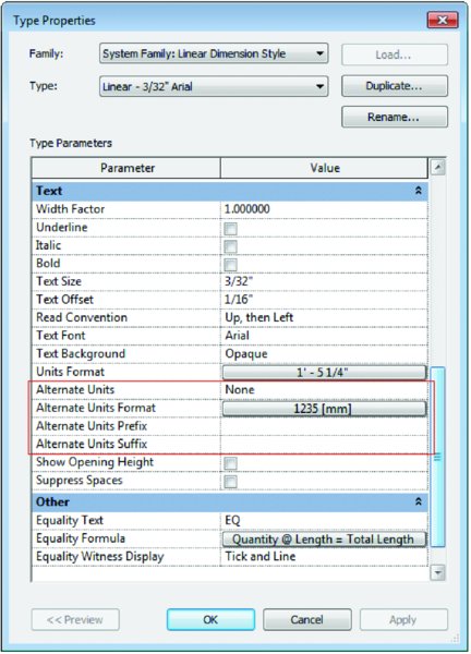
Figure 18.41 Alternate Units settings
Let’s explore how to use this tool:
- Continuing from the previous exercise, select the dimension string B and click the Edit Type button in the Properties palette. You don’t want all the dimensions to show both sets of units, so click the Duplicate button and name the new dimension string Linear – 3/32″ Arial I/M (Linear - 2.5mm M/I for the metric file).
- In the same Type Properties dialog box, change Alternate Units to Below. Set the Alternate Units Format to Millimeters in the Imperial file (Feet And Fractional Inches in the metric file). So that you know the other number is a measurement in an alternate unit, in Alternate Units Suffix add mm in the Imperial file. The settings will look like Figure 18.42.
- Click OK to close the dialog box.
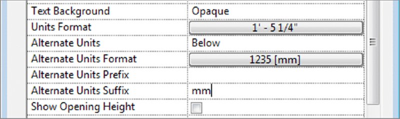
Figure 18.42 Alternate Units Format settings
You’ll see the dimension string with Imperial units above and metric units below (Figure 18.43).

Figure 18.43 Alternate units in the model
Annotating with Project and Shared Parameters
Every element in a project has a list of parameters. Some of these parameters, such as Assembly Code and Mark, are common parameters that are assigned to almost all object types. Others, such as Length, Height, and Volume, are unique to specific element types. Despite the plethora of default parameters, there are situations where you may need to add custom parameters to elements. These custom parameters, like the default ones, can be tagged and scheduled.
Depending on how you’d like to use a custom parameter, you can add them to your elements in a few ways:
- If all you want to do is schedule the new parameter, you have a couple of options:
- Add the parameter directly within the schedule itself. This will add a new parameter to your element family. Adding a parameter using this method adds it only to the element family in the schedule. For example, say you want to schedule the sound transmission class (STC) of a wall. You could add this property directly within the wall schedule and the new parameter would be available only to objects in the Walls category.
- Add the parameter to the project. Using this method, you can still schedule the new parameter, but you will have the option to add it to multiple categories. So, if you want to add a parameter for Unit Cost, you can add that to both your door and window categories at the same time.
- If you want to be able to both schedule and tag your parameter, you will need to create a shared parameter. This parameter is created as part of a separate file that is shared among the tag family, the element family, and the project. An example of this kind of tag might be for door security hardware. You can create a parameter that is assigned to a door family as well as a door tag that will allow you to designate whether or not a door has a card reader to gain entrance to a room.
In the following sections, we will discuss how to create both of these parameter types as well as the pros and cons of each.
Creating Project Parameters
You can create custom project parameters at any time in the project cycle. Depending on how you create the parameters, you can assign them to one or more element categories within the model. You can also assign them to elements that have already been created or to element categories for elements that you have yet to create.
 The following steps will allow you to make a custom parameter that can be scheduled but not tagged. For this example, pretend you are working on an existing building and reworking a space. Much of what is onsite will need to be demolished, but you would like to reuse all the elements that are salvageable. As you are documenting the existing conditions, you want to schedule the elements you want to keep. To do this, you’ll make a parameter called Reuse. Continue with the project file from the previous exercise (
c18-Dimensions-Start.rvt orc18-Dimensions-Metric-Start.rvt).
To add a new project parameter, follow these steps:
-
Go to the Manage tab in the ribbon and click the Project Parameters button.
This will display the Project Parameters dialog box (Figure 18.44).
-
Click the Add button to open the Parameter Properties dialog box. Here you will be asked to define a list of properties for the new parameter.
Let’s step through what these selections will be (Figure 18.45 shows a view of the completed dialog box).
-
Set Parameter Type to Project Parameter.
Choosing between project and shared parameter is the first choice you’ll need to make. We’ll get to shared parameters later, so for now, leave it at the default of Project Parameter.
- For Name, type Reuse. The name is used for describing the parameter as well as referencing it in schedules and the Properties palette.
-
Leave the Discipline setting at Common.
The Discipline drop-down menu will give you a few choices: Common, Structural, Electrical, HVAC, Piping, and Energy.
-
Set Type Of Parameter to Yes/No.
This setting dictates the format or behavior of the parameter. As you can see in Figure 18.46, a variety of parameter types are available. It’s important to understand some of these options and, more specifically, their differences. If you start creating formulas with your parameters, you’ll quickly understand how important it is to use the proper type. For instance, you cannot multiply Angle × Volume. Text cannot be added to a formula. Integers do not have decimal values. Many of these values are easy to understand if you apply a bit of logic.
-
For Type Or Instance, choose Instance. This setting controls the uniqueness of the parameter itself. Both parameter types can be mixed within a given family. In this example, use an instance parameter because you want to designate whether something is reusable on an element-by-element basis.
See Chapter 2, “Applying the Principles of the User Interface and Project Organization,” for more information on type and instance parameters.
-
For Group Parameter Under, choose Green Building Properties.
This setting is an organization tool. When you open your element properties, depending on how many parameters you add, you can develop quite a long list. This tool allows you to group new parameters into any given category.
-
In the list of categories, check the boxes for Doors, Furniture, and Windows.
Categories is the list of element types in which this new property will appear. This is where you define all the category types you’ll associate with the new parameter. Category selections are flexible. If you decide you need to change categories after you create your parameter, you can easily come back to the Project Parameters tool and modify your selection.
- When you finish, click OK. This will take you back to the Project Parameters dialog box, where you can choose to add another parameter or, in our case, just click OK to exit completely.

Figure 18.44 The Project Parameters dialog box

Figure 18.45 Setting the parameter properties (shown with Hide Un-checked Categories selected)

Figure 18.46 Listing of available parameter types
Back in the model, you can now select a door (because it is one of the categories you chose) and see that you have added a Reuse parameter in the form of a check box to the bottom of the Properties list (Figure 18.47).

Figure 18.47 The Reuse parameter in the family
Now that you’ve created a custom parameter in the project, it’s even easier to create one while in a schedule. You can create a custom parameter while creating a schedule or after the fact by modifying one. To create a parameter in a schedule, click the Add Parameter button in the Schedule Properties dialog box (Figure 18.48). Doing so opens the same dialog box that you see when you click the Project Parameter button, with the exception that the Categories selections will be grayed out because you can create parameters in schedules only for the element being scheduled.

Figure 18.48 Adding a parameter while in a schedule
Creating Shared Parameters
When you want to schedule and tag a custom parameter, you will need to use shared parameters. Previously in this chapter, you learned that customized project parameters are useful for scheduling the STC rating on a wall. You can also use them to schedule which doors have security systems as part of the door hardware set, for example, or to specify which equipment in a lab will require special gases (oxygen, argon, and so forth). None of these parameters exist by default in any families, but they are all values that you might want to tag or schedule, depending on the type of project you are working on.
These parameters do not exist in any of the tags either, so in order to tag these parameters, you need to create them in both the tag and the element families.
Don’t worry—it’s not as complicated as it all sounds, but you will need to follow some steps fairly closely. Once you have added a shared parameter to your project, you cannot modify it. If you want to change it, you’ll need to delete it and add the parameter again. So it behooves you to make your choices thoughtfully.
Let’s look at the workflow behind creating a shared parameter. You’ll do this by creating a custom wall parameter called STC so you can tag the sound transmission class of the wall types. To get started, continue using the c18-Dimensions-Start.rvt or c18-Dimensions-Metric-Start.rvt example from the previous exercise.
CREATING THE SHARED PARAMETER
The first thing you do is create a new, shared parameter file. This file translates the values of the shared parameter between the tag, family, and project. Follow these steps:

-
To create a shared parameter, go to the Manage tab in the ribbon and click the Shared Parameters tool.
Doing so opens the Edit Shared Parameters dialog box (Figure 18.49).
- Click the Create button to open the Create Shared Parameter File dialog box. Name your shared parameter file. For our example, we’ve named it STC; however, if you plan to make more than one shared parameter, you might want to name it something more universal. All of the shared parameters for a given project will ultimately live in the same file. Give the file a name and location that will make sense to the project team. Then click Save.
- Now that you’ve saved the TXT file, you’ll return to the Edit Shared Parameters window, where you’ll assign this parameter to a group by selecting New under the Groups option (this keeps like elements grouped together). This group is a hierarchical collection. So, for the wall’s STC, you will want to create a group called Wall Properties (Figure 18.50). This grouping allows you to easily sort different parameters within project categories. Once you name the group, click OK.
- Once you have a group, you’ll see that the Parameters buttons are now active. Click the New button and name the parameter STC. Leave the Discipline setting at Common. For Type Of Parameter, choose Integer. Because STC ratings are whole numbers, you can use the Integer type and eliminate any decimal places you’d have if you used Number as the type (Figure 18.51). Once you’ve entered the settings, click OK.
- You should see the new STC parameter in the Edit Shared Parameters dialog box. Click OK to exit this dialog box.

Figure 18.49 Creating the shared parameter

Figure 18.50 Creating a shared parameter group

Figure 18.51 Naming the parameter and setting the type
You’ve now created a shared parameter. The next step is to assign it to a category.
ASSIGNING THE SHARED PARAMETER TO A CATEGORY
The shared parameter is now defined, but you don’t have it associated with any categories yet. To do so, follow these steps:
- From the Manage tab in the ribbon, click the Project Parameters button to open the Project Parameters dialog box. You want to add a new parameter, so click Add.
- The Parameter Properties dialog box opens. This time, select the Shared Parameter radio button, and then click Select. In the Shared Parameters dialog box, select the STC parameter you just created, and then click OK. You’ll see that many of the fields are now grayed out in the Parameter Properties dialog box. This is because you have already specified this information in the shared parameter. In the Categories list, select Walls (Figure 18.52). Click OK to exit the dialog box.
- You’ll see the new shared parameter (STC) below your previous project parameter (Reuse) in the Project Parameters dialog box (Figure 18.53). Click OK to close the dialog box.
- Now that the STC parameter is part of the project, you can begin assigning values to it. Open the Level 1 floor plan and select one of the interior walls on the left side of the plan. By scrolling down in the Properties palette, you’ll notice that the STC parameter is now at the bottom (Figure 18.54). Enter a value of 45 and click Apply, or simply move your mouse out of the palette to set the value.

Figure 18.52 Assigning the shared parameter to a category

Figure 18.53 The shared parameter is now part of the project.

Figure 18.54 Giving the new parameter a value in the project
TAGGING THE SHARED PARAMETER
So far, you’ve created a shared parameter and added it to the Walls category in a project. These are all features you could have leveraged with a project parameter. The benefit of using a shared parameter is being able to tag it. The final step in this process is creating a tag to display the STC parameter in the wall:

- The first thing you’ll need is a new tag. Because you’re tagging a wall, and there isn’t a default wall tag type, you’ll need to make a generic tag and apply it to a wall condition. From the Application menu, select New ➢ Family. Open the
Annotationsfolder, selectGeneric Tag.rfa, and click Open. - Next, you’ll assign the correct category to the tag. By default, a generic tag is just that: generic. You want it to report information from the Walls category, so on the Create tab, in the Properties area click the Family Category And Parameters button.
- With the Family Category And Parameters dialog box open, choose Wall Tags from the list (Figure 18.55), and click OK. Delete the red text note in the tag family template before continuing.

- With the proper category selected, you need to add a label for your tag. From the Create tab in the ribbon, select the Label tool on the Text panel, and then click just above the intersection of the two reference planes in the view.
- In the Edit Label dialog box, select Type Mark from the list of category parameters and add it to the Label Parameters list to the right (Figure 18.56). This will call out the wall type and help you associate the proper wall with the STC rating. Click OK to close the dialog box and zoom in closer to the label you just placed.
- With the Type Mark parameter placed, let’s add the STC parameter. Activate the Label tool again, and then click just below the intersection of reference planes in the view. In the Edit Label dialog box, click the Add Parameter button at the bottom of the Category Parameters list. This opens the Parameter Properties dialog box (Figure 18.57). Click Select to open the Shared Parameters dialog box. Select STC and click OK, and then click OK again.
- You’ll now see the STC parameter in the Category Parameters list. Select it and add it to the right side of the dialog box (Figure 18.58). Click OK to close the dialog box.

- With all the labels added, you can brush up the tag with a bit of linework to help differentiate the tag from the rest of the drawing. On the Create tab, choose the Line tool from the Detail panel. Using the default options, draw a box around the two labels and a line between them (Figure 18.59). Once this is done, save the family as
Wall-STC.rfaand then load it into the project by clicking the Load Into Project button.
- Back in the project, you’re ready to tag the wall. Once you insert the tag into the project file, Revit will automatically begin the tagging command. However, the other way to begin tagging is to choose Tag By Category from the Annotate tab. Select the wall to which you have already given a value of 45 for the STC. You’ll see the wall type and STC rating populate within the tag (Figure 18.60).

Figure 18.55 Selecting the Wall Tags category

Figure 18.56 Adding the Type Mark parameter

Figure 18.57 Choosing the shared parameter

Figure 18.58 Adding the STC parameter to the label

Figure 18.59 The customized wall tag

Figure 18.60 The shared parameter now shows up in the tag within the project.
Once you’ve stepped through this workflow a few times, it will quickly become familiar and you’ll be able to add custom parameters to projects and tag them without a second thought. One thing to keep in mind while you’re doing all this, however, is that once you have added a shared parameter to your project, you will not be able to change any of the properties of the parameter itself. If you set the parameter type to Integer but you really wanted Number, you’ll need to delete the parameter and start over. Also, when working with a team, remember that shared parameters work much like keynotes with their external TXT files. If you are sharing the project file with the idea that it will be edited by another team, be sure to include the shared parameter file.
The Bottom Line
Annotate with text and keynotes. Although a picture is worth a thousand words, you will still need notes to make drawings understandable and be able to call out key elements in each view. Know how to create and modify text and keynotes for a complete set of documents.
Master It To properly use the keynoting feature, you’ll need to understand what each of the three keynote types do and how they’re used. List each and explain how they can be used in a project.
Use tags. Tags are text labels for elements such as doors, walls, windows, rooms, and several other objects that architects typically need to reference in a set of drawings. These tags typically refer back to other schedules or information in other portions of the drawing set and are unique to the view in which they are inserted.
Master It Inserting tags quickly can be a good way to make documentation time more efficient. How can you quickly tag a number of elements in the model at the same time?
Add dimensions. Dimensioning is a critical part of the project documentation, allowing you to communicate the distance elements are from one another.
Master It Adding dimensions is a necessary part in any project. However, in a project workflow you will typically want to change the location of a dimension’s witness line without having to re-create the entire dimension. How do you move a witness line without remaking the entire dimension?
Set project and shared parameters. Revit Architecture lets users add as many custom parameters to an element as are needed to document the project. These parameters can be both tagged and scheduled, depending on how they are made.
Master It You need to add a custom parameter for your project to track the percentage of recycled content in materials. What’s the best way to go about doing this?