
Chapter 14
Designing with the Family Editor
In previous chapters, we have discussed the modeling techniques for system families such as walls, roofs, floors, and ceilings. Although system families are essentially rule-based assemblies applied to sketch-based forms, component families are more self-contained. Another way to explain the difference is that system families are the objects you usually quantify in terms of linear units, surface area, or volume, whereas component families are most often counted objects. Such families include doors, windows, furniture, light fixtures, plumbing fixtures, and so on.
In Autodesk® Revit® Architecture software, the Family Editor is where you’ll create these component families. If you’re familiar with other 3D modeling applications, the good news is that it will be easy to get started. But the really great news is that if you’ve never modeled in 3D, learning to create 3D content for the first time in Revit is a very satisfying process.
So relax, and prepare yourself for getting excited about design. Once you understand how to create parametric content in the Family Editor, you’ll probably realize you can do anything in Revit. We’ll begin this chapter by discussing some of the general topics that are important to understand about the Family Editor and creating component families. Then you will use some of this knowledge to create your own component family in a detailed exercise.
In this chapter, you’ll learn to:
- Get started with a family
- Create the framework for a family component
- Understand family modeling techniques
- Apply extended family management techniques
Getting Started with a Family
Many generic 3D modeling applications allow you to create content that will be used in designing your buildings, and modeling in 3D is certainly a big part of the Family Editor. But the key to the Family Editor is that you’re not just modeling; rather you are modeling something specific. The thing that you’re trying to design is meant to be a particular thing and behave in a particular way.
So when you’re modeling in the Family Editor, you’re not just trying to model how and what something is; you’re also trying to predict how it might change. Anticipating change is essential to creating great, flexible content that is able to quickly and easily reflect your design changes.
For example, take a simple table. If you were to model this table in a program like Rhino, what you’d have when you’ve finished is exactly what you’ve modeled. But think about the design process and how often during design you’ll need to iterate something like height, length, width, or material. In the real world, each of these parameters is critical. Suppose you have only three options for each of these values—this results in 81 permutations! Who has time to manually create each of these options? But this is what you’d have to do if you were using a generic modeler rather than Revit, where these options are driven by rules. By using parameters to define dimensions, materials, nested elements, and more, you can create additional permutations on the fly.
Understanding In-place Families
In the previous chapter, you learned how to create an in-place void family in order to customize the edge of a floor slab. Although some truly unique content in your project can be modeled using in-place families, it is often a dead-end process that robs you of hours of otherwise productive time for a number of reasons.
First, an in-place family should be used only in cases where the object that you’re making is not likely to be moved, rotated, or copied. Any attempt to move, rotate, or copy an in-place family can often have unintended consequences that are difficult to remedy. For example, if you model an in-place family and then create copies in your project, they may all initially look the same, but in fact you’re creating new unique families—not just copied instances of the same family. Therefore, if you modify one of the copied instances of an in-place family, the other copy will remain unchanged.
Second, each copied instance will schedule independently from the other instances as separate line items. This is often not desirable because you may want to group like elements together in a schedule.
Finally, there’s no way to convert an in-place family into a component family. In some cases, you can copy and paste sketch lines or other 2D elements between the project and family environments. But if you try to copy and paste geometry from the project environment to the Family Editor, you’ll get an error stating that you can’t copy between family and project. The only way to proceed is to start again in the Family Editor.
 Choosing the Right Family Template and Category
The first thing you’ll want to consider in creating a component family is to determine what kind of component you want to build—in other words, you need to select an appropriate category. As we discuss in various chapters throughout this book, there are many predefined categories within a Revit project. You can create a new family from the Application menu by clicking New ➢ Family. This command will open a dialog box where you can choose from a vast selection of family templates (Figure 14.1). Templates for component families use the RFT file format.

Figure 14.1 Select a family template to begin creating a component family.
 From the New Family dialog box, select
 Generic Model.rft or Metric Generic Model.rft and then click Open. If you can’t find either template file, you can download them from this book’s web page at www.sybex.com/go/masteringrevitarch2016. Selecting the right family template is important because it determines a lot of the family’s behavior. For example, a baluster template contains default datum objects that relate to the geometry of a railing (Figure 14.2).

Figure 14.2 A baluster family template contains predefined datum objects to manage the geometric behavior.
Aside from some specific cases like balusters, the family template’s primary function is to assign a category. In some cases, you can change the category of the family after it has been created. In the family you just started to create, switch to the Properties panel in the Create tab in the ribbon, and then click the Family Category And Parameters button. In the dialog box shown in Figure 14.3, you will see that this Generic Models family is capable of being assigned to another category. This is helpful if you need to schedule a family in a different category than the one you initially selected. But in many cases, categories cannot be switched, and hosted or face-based components cannot be changed to unhosted (and vice versa). It is also difficult to convert a family that has many modeled elements to another category because you may be forced to reassign all the modeled elements to new subcategories.

Figure 14.3 Switching between family categories
Some categories are hardwired for specific behavior, and if you change from one such category to another, you can’t go back. For example, if you start a family in one of the baluster templates, you can switch to another category. But after having done so, you cannot switch the family back to being a baluster. Knowing what you want to create before you begin helps you minimize the amount of switching you need to do later in the process.
You should become familiar with the following characteristics that relate to a family’s assigned category.
SCHEDULING
Remember that as you start a new component the category you select controls how the family component will schedule. For example, you wouldn’t select the Furniture category to develop a family that you want to schedule as a plumbing fixture. Most of the categories you will use as you develop custom content will be self-explanatory; however, there may be some building elements for which you may need to think about categorization. One example is a vertical circulation component such as an elevator or escalator. You might select the Specialty Equipment category, but that category does not allow the geometry to be cut in a plan or section view. Perhaps you would use the Generic Models category instead, but you would need to use other parameters to schedule these types of families separately from other generic model families in your project.
USING PROJECTION AND CUT VALUES
Another important characteristic of the family category is that it will control whether a family will “cut” when intersecting a view plane (plan, section, elevation, and so on). For example, convention dictates that when furniture encounters a cut plane, you should show a projected view rather than a sectional view.
Revit respects this convention by cutting some categories while not cutting others. You can figure out which categories cut or don’t cut by going to the Manage tab and clicking Object Styles. As you can see, categories such as Casework, Ceilings, and Columns have line weight values in the Cut column, whereas categories such as Electrical Equipment, Furniture, and Lighting Fixtures do not.
ASSIGNING PARAMETERS
As you start to get into the parameters that can control a family’s geometry, material, or other value, keep in mind that it’s not always necessary to create components as fully parametric. This is especially true of the first pass. The location and spacing of content are often more important than whether the family can flex geometrically.
Nonparametric families often occur when the component being modeled is specific and highly unique. It may have parameters that control materials or a few other values, but not much more. At this point, little more than selecting the right category and insertion point is necessary. It’s often far more efficient to maintain design relationships by modifying the component in the Family Editor and then reloading it into the project—at least until more is known about the design. When more is known, you can open the family and embed more parameters.
Choosing Between Hosted and Nonhosted Family Types
The next important question you need to ask yourself as you select your family template is whether the family is meant to be hosted or nonhosted. If you make the wrong decision here, you’ll have to start over to switch between these types. To identify the difference between hosted and nonhosted family types, examine the family templates shown previously in Figure 14.1. Some of the filenames are indicated as “ceiling based” or “wall based.” These templates are used to create hosted families. Most of the other templates such as Casework.rft, Furniture.rft, Metric Casework.rft, Metric Furniture.rft, and Metric Generic Model.rft are nonhosted.
First, keep in mind that hosted objects are meant to cut or create an opening or depression in their host. Obviously, a window needs to cut the wall into which it will be placed, or a fire extinguisher case will often need to generate a recess in the host wall. Second, if the component is to be hosted and you’re certain that it needs to create an opening in its host, it can cut only one type of host. For example, a lighting fixture that is wall-based may not be hosted by a ceiling.
Want to see a bad example of this? Download and open the Tub-Rectangular-3D.rfa family from this book’s web page (Figure 14.4).

Figure 14.4 Wall-hosted plumbing fixtures
What’s wrong with this picture? First, this tub is wall hosted and not all tubs need walls, so you’ll have to make another family that has no host in order to place the tub where there is no wall. This seems a bit redundant because one tub will do.
Second, if you delete a host, all the hosted elements are deleted as well. This makes some sense when you delete a wall that hosts windows or doors. But it will certainly lead to a lot of frustration if you delete a wall that hosts bathroom fixtures!
We can’t stress this enough: You should avoid creating hosted relationships between objects that do not require hosting (that do not cut or otherwise modify the host). This discussion brings up an interesting point. Rather than use hosted elements, why not make elements face-based? There are some advantages:
- You don’t have to decide on a particular host. Any surface will do: Wall, Ceiling, Top Of Casework, anything that has a face. This is great if the lighting component you’re creating needs to cut into a wall, floor, and ceiling!
- A face-based element can cut the face of geometry in both the project and family editing environment. So the light fixture that cuts a wall in a project can cut the face of a piece of casework in the Family Editor.
- Deleting the host will not delete the component. Is this desirable? Maybe sometimes, but not always. What’s important is that you have the option if the component is face-based. You won’t have the option if the component is hosted.
- You can place face-based families on host elements from a linked project model. This works great when an architectural model is linked into an engineer’s model for placement of electrical or plumbing fixtures.
Creating Other Types of Families in the Family Editor
Now that you understand the importance of selecting between a hosted or nonhosted family template, you should become familiar with some other types of families you can create in the Family Editor.
PLACING LINE-BASED COMPONENTS
This is a less common type of family that allows you to place components in the project environment as lines. Line-based families can take advantage of line-based tools such as Trim/Extend and Split and can also support parametric arrays.
Generic model, detail item, and structural stiffener are the only family categories currently available to be used as a line-based component. An example of one is a generic model created by Steve Stafford for his Revit OpEd blog (Figure 14.5). This family is used to lay out egress paths and then calculate the total travel distance in a schedule. You can download this family here:

Figure 14.5 An example of a generic line-based family
USING DETAIL COMPONENTS
Some types of families consist of only 2D elements—these are called detail components. They are most often used in drafting views; however, detail components can also be placed in plan, elevation, and section views. The benefit of using detail components, as compared to individual lines and filled regions, is that a detail component can be reused many times, thus increasing drafting productivity; quality is increased by allowing control of repetitive detail elements and they support keynote and tagging abilities. We discuss detail components further in Chapter 16, “Detailing Your Design.”
PLACING ANNOTATION SYMBOLS
Much like detail components, annotation symbols are families that contain only 2D graphics, including lines, text, and fill or masking regions. They are different from detail components because annotation symbols will react to the scale of the view in which they are placed. Aside from the common uses of annotation symbols such as tags, north arrows, or graphic scales, you can nest annotation symbols in other types of model families to customize and better manage your approach to project documentation. Consider some of the families for electrical terminal fixtures in the default library. These families include a 3D representation of a small element, such as a receptacle plate that will be seen in an elevation view, but they also include a generic annotation to represent the object with a scaled symbol in a plan view, as shown in Figure 14.6.
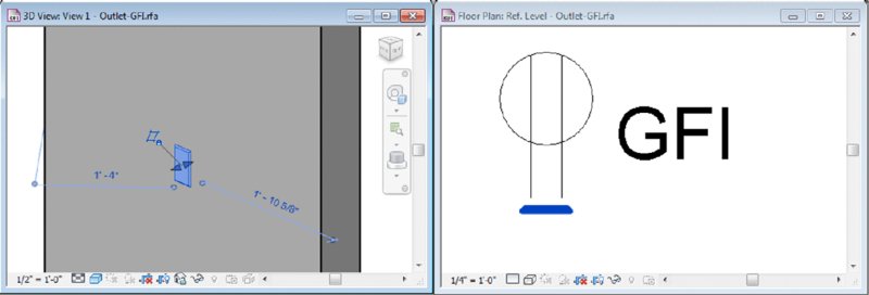
Figure 14.6 A default family illustrating a nested annotation symbol
In Chapter 4, “Configuring Templates and Standards,” we showed you how to build custom annotation symbols for use in your own projects or templates.
CREATING MASS FAMILIES
Mass families are special components that are created in a slightly different environment of the Family Editor called the conceptual design environment (CDE). Within this environment, you use tools to sketch lines that are used to generate forms almost automatically. As shown in Figure 14.7, the line tools in the ribbon of the CDE allow you to sketch first, select lines, and then use the Create Form button. After a form has been created, it can be subdivided for additional articulation.

Figure 14.7 Geometry tools in the conceptual design environment
USING MASS FAMILIES WITH AN APPLICATION
We discuss using mass families with greater detail in Chapter 8, “Advanced Modeling and Massing.” If you have an Apple iPad or Android tablet, you might also want to experiment with the free Autodesk® FormIt mobile application. It’s also available as a web application here: http://beta.autodeskformit.com. With this design application, you can quickly generate and study forms—including the ability to analyze gross floor area and shadows (Figure 14.8). When the app synchronizes with your Autodesk® A360 cloud account, it will automatically convert the designs to RVT project files where the modeled geometry is represented as in-place masses.

Figure 14.8 The Autodesk FormIt application can be used to generate mass forms.
USING ADAPTIVE COMPONENTS
Finally, a special type of dynamic family that is used in the CDE is known as an adaptive component. These families are an adaptation of the pattern-based curtain panel concept, but you can use them in geometry other than divided surfaces. You can learn more about creating and using adaptive components in Chapter 12, “Creating Walls and Curtain Walls,” and Chapter 9, “Conceptual Design and Design Analysis.”
Understanding the Family Editor
The Family Editor isn’t a different software application that you need to install. It is simply a unique mode within Revit that has tools and commands specifically designed to create component content. After you launch the command to make a new family and you choose a family template, you will enter the Family Editor. If you happen to have a project file open, you can switch back and forth between a family file and the project just the same way you’d toggle between the open views of a project.
Depending on the type of family you are building, the Create tab in the ribbon will have slightly different tools. In this chapter, you will be using the Furniture family template, and the Create tab will have specific 3D modeling tools, as shown in Figure 14.9.

Figure 14.9 The Create tab for model families
If you were creating a detail component or annotation family, neither of which can contain 3D geometry, the Create tab displays only 2D tools such as Line, Filled Region, and Label (Figure 14.10).

Figure 14.10 The Create tab for detail and annotation families
Within the Family Editor, you also have the ability to include imported CAD data. From the Insert tab in the ribbon, you can use the Import CAD tool to utilize 2D or 3D information from another source. You cannot use the Link CAD tool in the Family Editor; therefore, any data imported to a family will not update if the original CAD file is changed.
A feature in Revit is the ability to explode and then manipulate imported 3D solid CAD geometry. You can experiment with this feature by downloading the file ImportCAD.sat from this book’s web page.
Switch to the Insert tab, click the Import CAD tool, and then browse to the location where you downloaded the sample SAT file. You’ll have to change the Files Of Type drop-down list to ACIS SAT Files. Use the default settings and click Open. After the model has loaded, go to the default 3D view and press ZF for the Zoom To Fit command. Select the imported geometry, and from the contextual tab in the ribbon choose Explode ➢ Full Explode. Select the solid geometry again, and you’ll notice that the imported model is now ready to be manipulated with a series of grip controls (Figure 14.11). Delete the imported geometry before continuing with the exercise in this chapter.

Figure 14.11 Imported solid geometry can be exploded and manipulated.
Another tab in the Family Editor that might seem familiar is the Annotate tab. Here you will find tools for dimensions, symbolic lines, and text. In a model component, dimensions and text placed in the Family Editor are not visible when the family is loaded and placed in a project. Although text can be used for reference notes in the Family Editor, dimensions are used to control and drive the geometry. You’ll learn much more about parametric dimensions later in this chapter.
The tools in the Detail panel of the Annotate tab in the ribbon allow you to create some 2D geometry within a 3D family. This is especially useful if you have a somewhat complex model that you would like to display as a simplified graphic in a plan view. For example, you may have a detailed 3D model of a bathroom water closet (toilet) fixture. If such a model was composed of complex curved surfaces and solids, displaying many of these components in a project view might ultimately begin to degrade visual performance. Instead, the 3D geometry can be assigned to not display in a plan view, while you include a simple sketch of the fixture in the plan view of the family. Your renderings, sections, and elevations will display the 3D family geometry, while your plan views will remain simple and fast.
One final aspect to understand about the Family Editor is the ability to use multiple views to visualize your design. Similar to the project environment, it lets you create as many views as you need to help visualize the content in your family. The Ref. Level plan view can be duplicated if you need to examine your family at different elevations. Simply change the View Range properties of each plan view to control the height of the view’s cut plane. From the View tab in the ribbon, you can also create camera views and sections within the family.
Developing the Framework for a Family Component
Now that we’ve discussed some of the basic definitions and rules of the Family Editor, we’ll talk about the hierarchy of creating a family component.
In this section you will work through the fundamentals of creating a family in terms of datum objects, constraints, parameters, materials, subcategories, and visibility settings. Later in the chapter, you will learn more advanced modeling and parametric techniques.
Click the Application menu and then select New ➢ Family. Use the Furniture.rft or Metric Furniture.rft family template, which is available for download with this chapter’s exercise files from the book’s web page.
Creating the Necessary Reference Planes, Lines, and Points
In the project environment, datum objects are available for you to control and manage the location and behavior of modeled geometry. In previous chapters, we have discussed the use of grids, levels, and reference planes, but these data are also extremely important in a component family. When used in the Family Editor, reference planes, lines, and points will function as the skeleton for the solid and void geometry you build.
To be clear about the usage of datum objects in families, they are not required to construct geometry; however, if you’re confident that what you’re about to model in the Family Editor will need to flex (have a modifiable length, angle, location, and so on) from within the rules of the family, then it’s important that you begin by first creating the rules that will allow the geometry to move.
With few exceptions, you don’t want to give parameters to the geometry itself. Instead, you’ll want to create the necessary reference planes, lines, and points first. Then associate the parameters to these references and whenever possible test the parameters to make sure the references are flexing properly. Once you’re confident the references are flexing, you can build the geometry in context to the references, again testing to make certain that when the references flex, the geometry is flexing as well.
The type of datum object you use is based on how you want the geometry to flex:
Reference Planes These define a single plane that can be set to host sketch lines or geometry. They’re best for controlling linear geometric relationships—that is to say, geometry that will flex in a linear fashion. Reference planes don’t have endpoints. This is important because you don’t want to use reference planes for controlling angular or directional relationships.
As illustrated in the plan view of the
Desk.rfafamily, the linear parameters of Depth and Width are appropriately assigned to reference planes. All of these geometric constraints are parallel to one another (Figure 14.12).
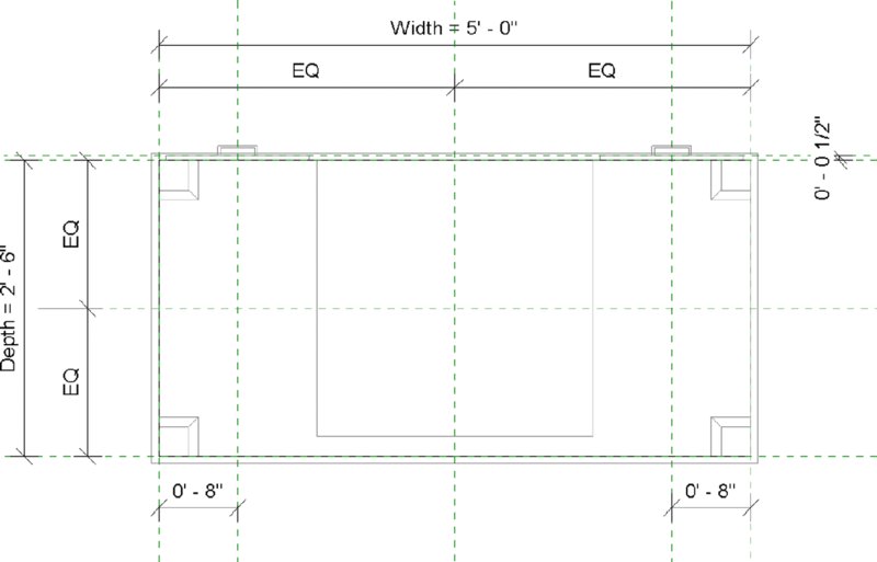
Figure 14.12 Reference planes controlling the parameters of the default Desk.rfa family
Reference Lines By definition these datum objects have endpoints and are great for controlling angular and directional relationships. They can have four axes of reference, two along the length of the line (which are perpendicular to each other) and one at each end that is perpendicular to the line.
You can also create curved reference lines, but they have only planes that may be used for hosting at each end. There are no references along the curved line, as shown in Figure 14.13.

Figure 14.13 Straight and curved reference lines
As an example, reference lines can be established in a family with length and angular dimension parameters to control path geometry for sweeps such as the iterations shown in Figure 14.14.


Figure 14.14 Sweep geometry using reference lines
Reference Points This type of datum object is available only in certain family templates, including Mass, Generic Model Adaptive, Generic Model-Pattern Based, and Curtain Panel-Pattern Based. Reference points have three planes that can be set to host sketch lines or geometry. You can also use a series of points to control a line or even a spline. Other objects, such as reference lines or other geometric surfaces, can also host reference points. You can select reference points from the Draw panel in the ribbon as shown in Figure 14.15.


Figure 14.15 Reference points in the Draw panel
SETTING THE BEHAVIOR OF REFERENCE PLANES AND LINES
When you place a new reference plane or line or select one already in your family, you will notice a property in the Properties palette called Is Reference. This setting is an important factor in how the family will behave when it is placed in a project. It affects how you can dimension or align to the family as follows:
- Not A Reference—The reference will be used only to control geometry in the Family Editor.
- Weak Reference—The reference can be accessed for measurement in the project environment only by pressing the Tab key on the keyboard.
- Strong Reference—The reference has the highest priority for dimensions and alignment. Temporary dimensions are displayed at the strong reference data.
In the Family Editor, reference planes also have other available values for the Is Reference property including Top, Back, Bottom, Left, Right, and Front. These values are all strong references and are provided to help you better organize your family geometry.
You will also notice that symbolic lines have a property called Reference with settings identical to those for the Is Reference property of reference planes and reference lines. We recommend that you treat symbolic lines with the same care as the datum objects.
Use the strong and weak references sparingly throughout your family. The default setting for the Is Reference property is Weak Reference; therefore, there could be a large number of possibilities for measurement within every component in your project. For every strong or weak reference, Revit must analyze the reference when you are annotating or designing.
SETTING THE INSERTION POINT
![]() After you’ve chosen an appropriate family template, the rest is pretty flexible. If you make any mistakes, you’ll probably be able to recover most if not all of your work to correct the problem. But some considerations should come before others, which is why we believe that the insertion point is the next most critical criterion on your list for family creation.
After you’ve chosen an appropriate family template, the rest is pretty flexible. If you make any mistakes, you’ll probably be able to recover most if not all of your work to correct the problem. But some considerations should come before others, which is why we believe that the insertion point is the next most critical criterion on your list for family creation.
First, the insertion point determines the location about which the family will geometrically flex. But second (and often more important), the insertion point is the point of reference when two family components are exchanged. This is critical if the “design” family that you’ve used as a placeholder is being swapped out for something more specific at a later date. If the insertion points are not established similarly between families, the location of the new family will not agree with the location of the old one.
For example, most of the tables in the default Revit furniture library define the insertion point at the center of the geometry, as shown in Figure 14.16. If you place one table family in your project and then later decide to swap it for a different table family, there should be minimal disruption to the layout of other furniture in your design. The new family will appear in roughly the same spot as the originally placed family. Now what happens if you were to download a table family from a web-based content provider? Will that table also follow the same convention for the location of the insertion point? This concern illustrates the importance of following published guidelines or standards for content creation.

Figure 14.16 Insertion point for default table families
Keep in mind that changing the insertion point is easy. As you might expect, you don’t move the geometry to the insertion point. Rather, you simply select two reference planes and then make sure the Defines Origin parameter is selected in the Properties palette. Continuing with this chapter’s exercise using the Furniture.rft or Metric Furniture.rft template, the two reference planes provided already are assigned the Defines Origin property. You will now start to build a geometric framework around these reference planes.
Let’s place some reference planes in the new family to officially begin the chapter exercise.

-
Activate the Ref. Level floor plan in the Project Browser. From the Create tab in the ribbon, click the Reference Plane command and sketch four new reference planes around the two existing reference planes, as shown in Figure 14.17.
The exact placement of the new planes doesn’t matter for now.
-
Select the reference plane you added to the left of the center plane, and in the Properties palette set its Name parameter to Left.
Assigning a name to a reference plane will allow you to use it later as a work plane for creating solid forms.
- Select the reference plane you added to the right and set its Name parameter to Right. Select the one near the top of the view and name it Back, and then select the one near the bottom of the view and name it Front.
- Activate the Front elevation view and add another reference plane above and parallel to the Ref. Level. Again, the exact placement doesn’t matter for now—just make sure it is parallel to the level. In the Properties palette, set the Name parameter for this reference plane to Top.

Figure 14.17 Adding new reference planes to the exercise family
The Is Reference property for these new reference planes will be set to the default value of Weak Reference. That is acceptable because these will be the major geometrical references of the table family. As an option, you can set the four reference planes in the plan view to Strong Reference and observe later how they behave in the project environment.
Using Dimensions to Control Geometric Parameters
Dimensions are useful for controlling the geometric parameters of your families; however, we recommend they be placed directly on reference planes and lines and not within the sketches of solid or void forms. When you start to construct a component family, you should first lay out any reference planes or lines and then add dimensions to the references—all before you create any solid geometry.
As you complete the exercise steps in this section, you will be creating the framework for solid geometry that you will build in subsequent sections of this chapter.

-
With the Front elevation view still active, start the Aligned Dimension command. You can access this command in the Measure panel of the Create tab in the ribbon, in the Annotate tab, or by pressing DI to activate the default keyboard shortcut. Place a dimension from the Ref. Level to the reference plane you previously created.
This process will consist of three mouse clicks: one on the Ref. Level datum object, one on the reference plane above, and a final click in open space to place the dimension string.
- Press the Esc key or click Modify in the ribbon to exit the Dimension command, and then select the dimension you just placed. To make this dimension parametric, locate the Label drop-down list in the Options bar and choose <Add Parameter…>. The Parameter Properties dialog box will appear, as shown in Figure 14.18. In the Name field type Height, and make sure the Type radio button is selected.
-
Click OK to continue. The dimension will now display with the prefix Height =.
The exact height doesn’t matter because you can control it later on through parameter manipulation.
- Activate the Ref. Level floor plan. You now need to ensure that the four new reference planes are equally placed around the two planes that define the family origin. After the equality constraints are established, you will place dimensions to control the overall length and width of the shape. The order of this procedure—equality, then overall dimension—should be followed to establish the correct relationship with a center-based origin.
- Place an aligned dimension between the three vertical reference planes, and then click the EQ symbol near the dimension string. Repeat this process for the horizontal reference planes so that the result looks like Figure 14.19.
- Next, you will add the dimensions that will actually control the overall size of the shape in plan. Place an aligned dimension between the outer two vertical reference planes, and then place a dimension between the outer two horizontal reference planes.
- Exit the Dimension command and select the horizontal dimension string. From the Label drop-down list in the Options bar, select <Add Parameter…>. Name the new parameter Length, and then click OK. Repeat this process for the vertical dimension string, and name the parameter Width.

Figure 14.18 Assign your first dimension to a new parameter.

Figure 14.19 Set equality constraints on reference planes first.
The result should look similar to Figure 14.20.

Figure 14.20 Establish dimension parameters in the plan.
MODIFYING PARAMETRIC DIMENSIONS
Now that you have established some dimensions and assigned them to family parameters, it is time to “flex” the geometry—a term that has become popular with Revit users since the early adoption years of the software. You flex your references by applying varying dimension values to confirm that no errors are generated and that the references are behaving the way you intended. Doing this early and often in the family-building process reduces the chance of encountering a problem that you can’t solve later on. When you have more forms and more complex parametric relationships, it becomes more difficult to unravel problematic geometry.
 There are two ways you can modify the parametric dimensions, thus flexing your family geometry. First, you can simply select a labeled dimension in the drawing area and enter a new value. The second way is different than in the project environment, where you must first select one of the objects a dimension references before editing the value. Although this method seems to be the easiest and most intuitive, you must be careful after you have established defined types within the family because direct manipulation of labeled dimensions will change the value of the most recent active type. For this reason, we recommend that you become accustomed to using the Family Types dialog box to flex your families.
You can create a new reference plane and dimension from the Create panel in the ribbon and then click the Family Types command. Move the dialog box off to the side so you can still see the drawing area and observe the reference planes and dimensions. In the Family Types dialog box, click the New button and create a new type named Type 1. Set the dimension parameters as follows, and then click Apply:
- Width = 2'-6" (750 mm)
- Length = 6'-0" (1800 mm)
- Height = 2'-6" (750 mm)
Click the New button again and create a new type named Type 2. Set the dimension parameters as follows, and then click Apply:
- Width = 3'-0" (900 mm)
- Length = 8'-0" (2400 mm)
- Height = 2'-6" (750 mm)
If the reference planes and dimensions were created properly, you should not receive any error messages while you are flexing the parameters. In case you do receive any errors, you could delete the dimensions and even the reference planes and start over. If this were to happen later in the process, it would be more difficult to resolve the problem, and many more hours would be lost if you had to start over.
Reviewing the Differences Between Type and Instance Parameters
In the previous exercise, you created a few dimension-based parameters that were set to be type parameters. Let’s review the difference between a type parameter and an instance parameter—keeping in mind that they can be switched at just about any time.
The key difference between the two is that modifying a type parameter always modifies all instances of the type. Think of a type as a set of identical elements. Change one item in the set, and all the other items of that type in the model change to match. Door sizes are a good example of this. Doors come in standard sizes: 32", 34", 36" (800 mm, 850 mm, 900 mm). On the other hand, an instance parameter modifies only the instances that you have selected. A good use of an instance parameter would be the fire rating on a door. Not every 36" (900 mm) door will be fire rated, so you’ll need to individually identify which ones are. Figure 14.21 shows the parameters of a default curtain wall door family.

Figure 14.21 Parameters of a default curtain wall door family
In Figure 14.21, the parameters that have the notation (Default) are instance parameters. There are other parameters that can be used to report dynamic values from within the family. These are shown with the (Report) notation. In the example of a standard door, dimensions such as Width, Height, and Thickness would be best established as type parameters because you wouldn’t want users to create random or arbitrary values. Also be aware that once a parameter is created, only some aspects of the parameter can be modified. You cannot change the Discipline or Type Of Parameter value after the parameter has been created.
On the other hand, each new option can create a lot of new types. By default, loading a family into your project will also load all the types. If you want to create the potential for many types but be selective about which types are loaded, you can use a type catalog to load only specific types.
USING TYPE CATALOGS
If you are creating a family that will have many different type iterations, you can consider using a type catalog instead of creating each iteration within the Family Editor. A type catalog is a text file that contains all the iterations of the parameters specified within a family. When you load a family into a project that has an associated type catalog, such as steel framing families, you are presented with a dialog box within which you can select one or more types (Figure 14.22). You can select multiple types by pressing the Ctrl or Shift key.

Figure 14.22 A type catalog allows you to choose types to load.
If you ever need to load additional types from a family you’ve already loaded in your project, you don’t have to locate the original family file. Instead, locate the family in the Project Browser, right-click it, and then select Reload.
To generate a type catalog, the easiest method is to first use the Export Types command from the Application menu. This process will export all available parameters and any types you have established in your family to an appropriately formatted syntax. Save the TXT file in the same location as the associated RFA file and with the same filename. For example, the type catalog associated with the W-Wide Flange.rfa family file is named W-Wide Flange.txt. Using the exact same filename is critical to using a type catalog because that is how Revit will associate the two files.
Open the TXT file with a text editor such as Notepad or Notepad++. Or you can open the file as a comma-delimited table in Microsoft Excel—as long as you save the file back to TXT format when you finish editing.
The first row of the type catalog will be a header that establishes the purpose for each column in the table. The syntax for the header is as follows:
ParameterName##ParameterType##ParameterUnits
Valid entries for Parameter Type are listed in Table 14.1 with the proper method for declaring them in the type catalog header. For measurement parameters such as Length and Area, the units can be adapted accordingly. Where the parameter declaration is listed as ParameterName, you will substitute a user-defined parameter name. Otherwise, the parameter name is built into the family and cannot be changed.
Table 14.1 Types of parameters supported in a type catalog
| TYPE OF PARAMETER | PARAMETER DECLARATION |
| Angle | ParameterName##ANGLE##DEGREES |
| Area | ParameterName##AREA##SQUARE_FEET |
| Assembly Code | Assembly Code##OTHER## |
| Cost | Cost##CURRENCY## |
| Currency | ParameterName##CURRENCY## |
| Description | Description##OTHER## |
| Integer | ParameterName##OTHER## |
| Keynote | Keynote##OTHER## |
| Length | ParameterName##LENGTH##FEET |
| Manufacturer | Manufacturer##OTHER## |
| Material | ParameterName##OTHER## |
| Model | Model##OTHER## |
| Number | ParameterName##OTHER## |
| Slope | ParameterName##SLOPE##SLOPE_DEGREES |
| Text | ParameterName##OTHER## |
| URL | URL##OTHER## |
| Volume | ParameterName##VOLUME##CUBIC_FEET |
| Yes/No | ParameterName##OTHER## |
| <Family Type> | ParameterName##OTHER## |
For Yes/No parameters in type catalogs, the value is defined as 1 = Yes and 0 = No. For the <Family Type> parameter, enter the complete name of the family with the type designation as Family Name:Type Name (without the file extension).
The first column in the table is where you will list the types within the family. In the first row of the table, the first value is blank—that is, the first row will begin with a comma delimiter when it is saved as a TXT file. After the header row is filled with parameter declarations and a list of type names is entered in the first column, you can start populating the values in the rest of the catalog. A sample of a type catalog opened in Excel is shown in Figure 14.23.

Figure 14.23 The type catalog for the W-Wide Flange family
Organizing Solids and Lines in a Family Editor
When you get beyond the basic geometric controls in families that are dictated by datum objects and dimensions, there are three other ways you can organize the solids and symbolic lines you create in a family:
- Object styles and subcategories
- Visibility settings
- Materials
Each of these three methods of control is directly related to the 3D and 2D content you generate. In other words, you must apply these settings directly to the solids and lines in a family. We will first review each method, and then you will learn about family-modeling techniques in the next section.
USING OBJECT STYLES AND SUBCATEGORIES
Let’s get back to the exercise file and discuss object styles and subcategories. As mentioned earlier in this chapter, Revit has predefined a number of family categories. These categories define how elements display, schedule, export, and so on. Even though these main object categories can’t be modified, you can create subcategories for model, annotation, and imported objects.
Although you can use subcategories to control the visibility of some part of the family, keep in mind that the detail level and visibility settings already manage visibility. The subcategories are most important when you’re exporting your project because each category and subcategory is permitted its own CAD layer or IFC classification (Figure 14.24).

Figure 14.24 Export options for categories and subcategories
So if your project is being exported to CAD in such a way that you’ll need to associate objects with granular layer settings, creating and assigning subcategories to elements is necessary. Although it’s best not to rely on subcategories to manage visibility, we will show you how to create a new subcategory in the exercise file and then assign geometry to it.
In your exercise file, switch to the Manage tab and choose Object Styles. In the Object Styles dialog box, click the New button and create a new subcategory named Tables, as shown in Figure 14.25. Click OK to close both dialog boxes.

Figure 14.25 Create a new family subcategory.
Remember that, unless you specifically need to isolate tables from other types of furniture in your project, you shouldn’t create too many subcategories because doing so creates an opportunity for inconsistency. What if someone else on your team created a different table family and added a subcategory called Table? When both families are loaded into a project, you will have two subcategories: Tables and Table.
Subcategories must be assigned to solid geometry or symbolic lines in the family in order to be utilized in the project environment. We will discuss this in the “Understand Family Modeling Techniques” section later in this chapter.
ASSIGNING VISIBILITY SETTINGS
The time it takes for Revit to generate or regenerate a view depends on how much stuff in the view needs to be displayed. When you’re building smaller parts of a larger component (or if the elements are not visible in certain orientations), you should assign those elements to reveal themselves only at a certain level of detail (or in certain views). Doing so prevents the software from managing more information than necessary and helps you keep your views uncluttered.
The Revit Model Content Style Guide published by Autodesk lists guidelines for assigning geometry to the three detail levels available in project views (Table 14.2).
Table 14.2 Guidelines for assigning detail level
| IF THE GEOMETRY IS: | SET THE DETAIL LEVEL TO: |
| Smaller than 1' (300 mm) | Fine |
| Between 1' and 3' (300–900 mm) | Medium |
| Larger than 3' (900 mm) | Coarse |
Source: Revit Model Content Style Guide by Autodesk
To practice using these visibility settings, download and open the file c14 Desk Project.rvt from this book’s web page. The sample project contains the default Desk.rfa family that is loaded in the Revit default project template. We have created a working sheet in which three 3D views have been placed with different Detail Level properties. Notice that all of the drawer faces and hardware are displayed in every view, despite the Detail Level assignments.
Double-click any one of the viewports you see in the sample sheet view to activate a view. Select one of the desks, and then from the contextual tab in the ribbon, click Edit Family. You should be in a 3D view once the Desk.rfa family opens. If not, activate the default 3D view. Select the two sets of drawer handles; press the Ctrl key to select multiple items. From the contextual tab in the ribbon, choose Visibility Settings. In the Family Element Visibility Settings dialog box (Figure 14.26), uncheck the boxes for Coarse and Medium. Because these handles are smaller than 1' (300 mm), they should be seen only when a view’s Detail Level is set to Fine. Also uncheck the Left/Right option because viewing the handles from the side might not be that valuable in a section or interior elevation view.

Figure 14.26 Family Element Visibility Settings for drawer handles
Notice that the box for the Plan/RCP option is unchecked. This is appropriate for the desk because little more than the surface of the top of the desk needs to show up in the plan. The legs, the hardware, and even the faces of the drawers don’t need to show up in the plan. Click OK to close the dialog box.
Next, select the drawer faces and then click the Visibility Settings tool. This geometry range is 1'– 3' (300–900 mm), so it should display at Medium and Fine detail levels. Also uncheck the Left/Right option (Figure 14.27), and then click OK to close the dialog box.

Figure 14.27 Visibility settings for drawer fronts
From any tab in the ribbon, choose Load Into Project and then select the c14 Desk Project.rvt file if you are prompted. Choose the option to overwrite the existing version, and return to the sample sheet view. You will now see that the appropriate geometry is displaying only at the most appropriate detail levels in each view (Figure 14.28).

Figure 14.28 Views showing a Desk family with appropriate level of detail
USING MATERIALS
Materials are crucial to a family. But what are often more important are the Shading setting and the Transparency value of the material because they communicate much about the intent of your design in the early stages (Figure 14.29).

Figure 14.29 Shading and Transparency settings in the Material Browser dialog box
![]() In addition, material options are often not easily created in Revit. Yes, a family can have a material parameter. But expressing many different materials for visualization purposes is probably best left to the visualization specialist, who understands the subtleties of creating a compelling image, not just a rendering of a working model—and it’s unlikely they’ll be using Revit for this purpose.
In addition, material options are often not easily created in Revit. Yes, a family can have a material parameter. But expressing many different materials for visualization purposes is probably best left to the visualization specialist, who understands the subtleties of creating a compelling image, not just a rendering of a working model—and it’s unlikely they’ll be using Revit for this purpose.
Beyond visualization, however, materials in Revit are used for a host of other things. Graphic representation in construction documents and material takeoffs are two examples. If the materials in your families are something you will need to schedule or view graphically, it’s a good idea to define them.
Multiple materials can be assigned to a family. They are assigned based on model solids, so if you have multiple solids (sweeps, extrusions, and the like), each one can be given a unique material.
You have two options to define a material within a family, both being handled in the solid’s object properties shown in the Properties palette. By default, the material is set to <By Category>. Select this option and you can change the material to any material shown in the Material Browser dialog box, or you can load a new one from any material library. This is a great use for the family if you know the material is not going to change. If you know that your casework is not going to be anything but blonde maple, for example, go ahead and set the material within the family. Your other option is to use the tiny button […] to the right of the Material field in the Properties palette to define a new parameter. In this case, you can call the material something like Casework Material. If you were to use this same parameter for all your casework families, once it’s placed in the model you can change that material via the Material Browser dialog box, and it will update all your casework families at once.
Modeling Techniques in the Family Editor
Creating complex geometry isn’t always as easy as opening the Family Editor and starting to model the shape that you think you’re trying to create. Sometimes you need to model one form in order to create another form. And sometimes you need to model a complex, parameterized form in order to parameterize the actual shape that you’re trying to create. So that you understand these advanced techniques, we’ll first cover the available geometry types that can be created in Revit.
There are five discrete geometry types in the Family Editor: Extrusion, Sweep, Blend, Revolve, and Swept Blend. Both solid and void forms can be modeled from these shapes. In this section you’ll learn how to create all of these types, along with the Family Editor technique of nesting families.

Which type you select is important, but our advice is to use the simplest form that will express what you’re trying to model, keeping in mind how the geometry is likely to change.
Creating an Extrusion
Let’s get back to the furniture exercise where we are constructing a table. Activate the Ref. Level floor plan, and from the Create panel in the ribbon click Extrusion. The first action we will take is to specify a work plane to host the extrusion. If you don’t specify a work plane, the default plane will be the level associated with the current view.
- In the Work Plane panel in the contextual tab of the ribbon, click Set. In the Name drop-down list within the Work Plane dialog box, choose Reference Plane : Top, as shown in Figure 14.30.
-
In the Options bar, set the Depth to –0'-2" (–50 mm).
This will allow the top of the extrusion to be aligned with the Top reference plane, with its thickness extruding downward—away from the work plane.
-
In the Properties palette, set Subcategory to Tables. For the Material parameter, click the small button to the right of the parameter value field.
This button will allow you to associate a family parameter to the property instead of simply choosing one material to be assigned to the solid.
-
Click the Add Parameter button and create a new parameter named Tabletop Material. Click OK to close both open dialog boxes, and then you will see that the Material field is now inactive and the small button now has an equal sign label.
This means that the property is now being controlled by a family parameter.
-
In the Draw panel, choose the Rectangle tool, and then sketch a rectangle that snaps to the intersections of the outer reference planes (Left, Front, Right, and Back). Immediately after your second click to complete the sketch, you will see padlock icons at each of the four sides of the sketch. Click each one to establish an alignment constraint with the respective reference plane (Figure 14.31). If you click away and the constraint icons disappear, you will either have to delete and redraw the sketched lines, or you can use the Align tool to reestablish the constraint.
Click Finish Edit Mode from the contextual tab in the ribbon, and you’ll see the first solid piece of your exercise family. Activate a 3D view and open the Family Types dialog box. Switch between Type 1 and Type 2, and click Apply to verify that the extrusion flexes like the reference planes did previously in the chapter.
- Activate the Front elevation view, and add an aligned dimension from the Top reference plane to the bottom of the tabletop extrusion.
- Select the dimension, and from the Label drop-down list in the Options bar, choose <Add Parameter…>. Name the new parameter Tabletop Thickness, and then click OK.
- Open the Family Types dialog box again, and set the Name drop-down list to Type 2. In the Tabletop Material parameter, click the ellipsis button to launch the Material Browser.
- From the Material Browser, make sure the library panel is displayed by clicking the icon at the top of the document materials list. Search for “oak” at the top of the dialog box, and then select the material Wood (Oak) from the library panel. Click the up-arrow icon to load the material from the library into the family. In the Graphics tab of the Material Browser, check the box Use Render Appearance (Figure 14.32), and then click OK.
- Set the Tabletop Thickness value to 4" (100 mm) and then click Apply in the Family Types dialog box. Repeat steps 8, 9, and 10 for Type 1, but search for “glass” and load the material named Glass, Green. Set the Tabletop Thickness for Type 1 to 1" (25 mm), and then click OK to close the Family Types dialog box.

Figure 14.30 Set a named reference plane as the work plane.

Figure 14.31 Set the constraints of the extrusion sketch to reference planes.

Figure 14.32 Adding a material from the library and setting its graphic appearance
Creating a Sweep
Let’s have a little fun and assign a void sweep to the edge of the tabletop. It will be unique because we only want the sweep to cut the tabletop when Type 2 is selected—it will not cut the top for Type 1.
A sweep is a 2D profile that follows a path. The magic behind sweeps in the Family Editor is that a sweep path can be set to automatically follow other model geometry. A great example is the continuous tubular structure of the chair shown in Figure 14.33. As you can see in the sequence of images, a simpler solid form is generated and then converted to a non-cutting void, a path is generated along the edges of the void geometry, and a tube profile is applied to the path. To explore how this family was made, download the file c14 Tube Chairs.rvt from this book’s web page.

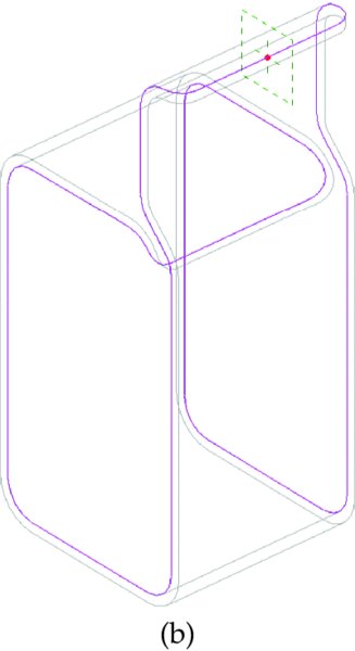

Figure 14.33 Solid geometry, converted to a noncutting void used to drive a complex sweep path
In this part of the chapter exercise, you will create a void sweep along the outer edge of the tabletop using the Pick Path tool. You will then assign a parameter to drive the void into or away from the solid extrusion, depending on which type is specified.
- Activate the default 3D view and set the graphic style in the view control bar to Shaded. Open the Family Types dialog box, select Type 2 in the Name drop-down list, and then click OK.
- From the Create tab, choose Void Forms ➢ Void Sweep. From the contextual tab in the ribbon, click Pick Path. In the 3D view, pick each of the four upper edges of the tabletop solid (Figure 14.34).
- Click Finish Edit Mode (the green check mark) in the contextual tab of the ribbon to complete the Pick Path command.
-
In the Sweep panel of the contextual tab, set the Profile drop-down list to c14 Table Void Profile.
This is a profile family we created and preloaded in the exercise file. You can also download it with the rest of this chapter’s exercise files for further exploration.

- Zoom into the area where the profile is applied to the path, and make sure the curved part of the profile is facing toward the tabletop solid (Figure 14.35). If it isn’t, click the Flip button in the Options bar.
- Click Finish Edit Mode in the contextual tab in the ribbon, and the void will automatically cut the tabletop solid.

Figure 14.34 Use the Pick Path tool to select the edges of the solid tabletop.

Figure 14.35 Adjust the sweep profile to face the solid.
When you create a void in the Family Editor, it will automatically cut any existing solids. If you don’t want a void to automatically cut other geometry, you can create the elements as solids first. When you are satisfied with the forms, select the appropriate solids and change them to voids in the Properties palette. Note that once a solid or a void is being cut by another object, you cannot change the solid/void property. You must use the Uncut Geometry tool first.
Because you used the Pick Path method to define the sweep path, the sweep will automatically update as the shape of the tabletop changes. This exercise is a simple example of a powerful tool with a plethora of applications.
Now that you have created a void that cuts the solid geometry of the wood tabletop type, you need to adjust it so that the profile does not cut the solid when the glass tabletop type is specified. Unfortunately, you can’t simply turn the void sweep on and off, but you can adjust its horizontal offset so it cuts like a virtual sliding saw.
- In the 3D view, select the void sweep. In the Properties palette, you will see the parameters that drive the profile within the sweep. Click the Associate Family Parameter button next to the Horizontal Profile Offset value.
- Click the Add Parameter button. Create a new parameter named Trigger Cut, and then click OK to close both dialog boxes.
- Open the Family Types dialog box, and for Type 2, set the Trigger Cut value to 0'-0" and then click Apply.
- Switch to Type 1 and set the Trigger Cut value to –0'-4" (–100 mm), and then click OK to close the dialog box. Figure 14.36 shows the difference between the two types just defined.


Figure 14.36 Void sweep cutting Type 2 (wood); not cutting Type 1 (glass)
You’ll see that adding the negative value to the Horizontal Profile Offset allows you to control whether the void cuts the solid tabletop. We simply assigned the offset value to each family type, but you could explore methods of using formulas with logic such as this:
If Tabletop Thickness < 4" then Trigger Cut = –4" else Trigger Cut = 0”
The actual syntax of this formula to be applied in the Family Types dialog box would be: if(Tabletop Thickness < 0' 4", -0' 4", 0').
Creating a Revolve
Let’s move on to the process of creating the legs for the table. You’ll use the Revolve tool to create this shape; however, you will create the shape only once in a separate family that will be loaded into the table family and placed multiple times.
We have created a preloaded family for the purpose of this segment of the exercise. Download and open the file c14 Table Leg.rfa from this book’s web page. You’ll create a revolve form, assign height and material parameters, and then load it into the table family.
-
In the
c14 Table Legfile, activate the Front elevation view. You will see that we have sketched a 2D profile consisting of invisible lines.These will not display when the leg family is loaded into the table family.
-
From the Create tab in the ribbon, click Revolve. From the Draw panel in the contextual tab, make sure the Pick Lines tool is selected. Hover the mouse pointer over one of the provided profile lines and press the Tab key once, and then click to select all the lines of the profile.
Don’t worry about constraining any of the sketch lines, because this shape won’t be dependent on adjacent geometry.
- Click the Axis Line tool in the contextual tab, select the Pick Lines mode, and then click the vertical reference plane in the drawing area.
- Click the Finish Edit Mode icon in the contextual tab to complete the Revolve command.
- Add an aligned dimension between the Ref. Level and the reference plane above the revolve. Select the dimension, and in the Options bar choose <Add Parameter…> from the Label drop-down list. Name the new parameter Leg Height, and make sure it is a type parameter.
- Select the solid revolve, and in the Properties palette click the Associate Family Parameter button for the Material property. Create a new parameter named Leg Material, and click OK to close the open dialog boxes.
Before you save the leg family and load it into the table family, you should consider whether the nested family needs to be scheduled—in the case of a table leg, probably not. However, you will load some chairs into the table family later and those will surely need to be scheduled.
Switch to the Create tab, and from the Properties panel click the Family Category And Parameters button. In that dialog box, you will see a list of Family Parameters that contains a parameter called Shared. When this box is checked, the nested family can be scheduled. For example, if you checked the box for the table leg family, loaded it into the table family, loaded the table family into a project, and then placed several instances of the table, you could create a schedule to count the total number of table legs in the project.
Creating a Blend and Swept Blend
When you create a blend, you are essentially combining two different shapes. Say you have a circle and want to transition it to a square. Creating that geometry by using an extrusion and voids would be complicated, but creating it with a blend is simple (see Figure 14.37).

Figure 14.37 A simple blend of a square and circle
The only difference between a blend and a swept blend is that a blend is defined along a straight line starting on a work plane. A swept blend is along a user-defined path. Figure 14.38 demonstrates a swept blend between a circle and a square along a user-defined path.

Figure 14.38 A swept blend
Both types of blends can incorporate a variety of shapes and profiles. Using the context of furniture that we’ve established, you’ll create a swept blend. You’re going to create a wooden stool.
-
To begin, open the default furniture family. You’re going to create a three-sided stool starting with the legs. When you open the default furniture family, you’ll be in the Ref. Plane view. In this view, choose the Swept Blend tool from the Create tab.
The Swept Blend tool has its own contextual menu, shown in Figure 14.39. You will create a path for the sweep and the starting and ending shapes. As you can see, the software first wants you to define a path.
-
Choose the Front elevation view to start the path, and pick the Sketch Path button from the Swept Blend panel. Using the Line tool (which is selected by default), start a line from 10" (250 mm) to the left of the base and continue until it intersects with the vertical plane at a 73° angle. You’ll have a measurement roughly 2'-10" (865 mm) across the hypotenuse of the triangle (Figure 14.40). Click the green check mark to accept the sweep.
Now you need to make the base of your leg.
- Open the Ref. View and you’ll see two red dots and a line connecting them. The dot on the left is the base of the leg, the dot on the right is the top of the leg, and the line between is the path you just created. Starting with the base, choose the Select Profile 1 button and then the Edit Profile button (Figure 14.41).
-
Using the left red dot as a center point, create a circle 1" (25 mm) in diameter. Click the green check mark, then the Finish Edit Mode button, to complete the shape.
Next, you need to create the top of the leg.
- Select the Select Profile 2 button and then Edit Profile from the Swept Blend panel. Using the Y-reference plane as the right side of the box, create a rectangle centered on the X-axis 1" × 3" (25 mm × 75 mm). Click Finish Edit Mode when you’ve finished. The two shapes will look like Figure 14.42.
- With those two profiles and a path complete, click Finish Edit Mode again to complete the sweep. You now have one leg of your stool.
- To finish the base, select the leg and choose the Array tool. In the Options bar, set these options:
- Choose a radial array.
- Leave the Number of arrayed items at 3.
- Change the Angle to 360.
- Change the rotation center to the middle of the X-Y reference planes.
-
Click OK to finish the array.
You should now have a set of stool legs (Figure 14.43).
-
From this point, use the techniques explained earlier in the chapter to add a round stool seat and a bar near the base for your feet.
Our finished stool is shown in Figure 14.44. There are a few ways to create the seat and bar—it can be with a swept blend, an extrusion, or even a revolve.

Figure 14.39 The Swept Blend contextual menu

Figure 14.40 Creating the leg sweep

Figure 14.41 Modify the two profiles to create the swept blend.

Figure 14.42 Finishing the two shapes of the blend


Figure 14.43 The completed stool legs

Figure 14.44 The completed stool
The finished family can be found on the book’s web page. The file is called c14-WoodenStool.rfa.
Before we continue with the table-modeling exercise, let’s take a moment to discuss the importance of nested families in comparison to modeling repetitive geometry all within one family. Families are used to create individual components. By combining those components, you can use a nested family to add parameters to better define the relationships between those components and best leverage the families within your project.
Nesting Families
Geometry from one family can be loaded into another family. This process is called nesting, and it allows you to create a single element that will be used many times in another family. This method is much more efficient than creating an element and then grouping and copying it around the same family. Let’s review some benefits of using nested families.
When one family is loaded into another, the nested family behaves as a single, unified component. This means that it will be much easier to change and control the instance placements of a nested family. Even though the nested family may seem like a static component, references and parameters in nested families can be driven by controls in the host family.
A nested family can also be controlled by a Family Type parameter, which will allow you to select from multiple nested families as another parameter in the host family. This feature is incredibly powerful for creating design iteration within families that are in your projects. You will see this functionality later in this chapter when you load two different chair families into the table family and use a Family Type parameter to select between them.
As a final note about nested families, you should always be aware of the insertion point defined in the families you load into other families. As we mentioned previously in this chapter, a consistent insertion point will ensure that a nested family doesn’t “flip-flop” in unintended directions when you switch between family types.
Let’s get back to the exercise for which you should still be working in the c14 Table Leg family file:
- Save the leg family and then click the Load Into Project button in the ribbon. The table family should still be open and the leg will be loaded (nested) into it. You will now place multiple instances of the leg family, associate the parameters, and adjust the visibility for control of an optional leg instance.
- Switch to the
c14 Tablefile, and activate the Ref. Level floor plan. From the Create tab, click the Component tool, and thec14 Table Legfamily should be the active component in the Type Selector. Look in the Properties palette at the Host property, and make sure that it is Level: Ref. Level. Place four instances of the leg near the corners of the table and one exactly at the crossing of the center reference planes. - Add dimensions for each of the four corner legs, and adjust the legs as necessary so that they are offset exactly 6" (150 mm) from each edge reference plane (Figure 14.45). Lock these dimensions to preserve the offset.
- Select the middle leg, and in the Properties palette click the Associate Family Parameter button for the Visible property. Click the Add Parameter button, and name the new parameter Middle Leg. This will be a Yes/No parameter that can be controlled with a logic formula that will be driven by the length of the table.
-
Open the Family Types dialog box, and in the Formula field for the Middle Leg parameter type the following: Length > 7' (for metric, type Length > 2000 mm).
This simple formula will make the middle leg visible when the Length parameter exceeds 7' (2,000 mm) and invisible when it doesn’t.
-
Switch to a 3D view, and now you’ll need to assign dimensional parameters to drive the leg heights in relation to the table.
You can do this a few different ways, but when you’re dealing with multiple instances of an object, we recommend you feed a value into a nested type parameter rather than aligning and locking each instance to reference planes within the host family.
- Select one of the legs, and then click the Edit Type button in the Properties palette. In the Type Properties dialog box, click the Assign Family Parameter (AFP) button for the Leg Height parameter. Add a new parameter named Nested Leg Height.
-
Click the AFP button for the Leg Material parameter, and add a new parameter named Nested Leg Material. Click OK to close the Type Properties dialog box.
You must associate the parameters in nested families with parameters in the host family—even if it is simply to allow materials to be assigned to the nested elements.
-
Open the Family Types dialog box. In the Formula field for the Nested Leg Height parameter, type the following: Height - Tabletop Thickness.
Make sure that the parameters are spelled exactly because they are case sensitive. This formula will use the overall height of the table minus the thickness of the tabletop to drive the height of the nested legs.
-
Switch between Type 1 and Type 2 to verify the behavior of the legs. Even though the middle leg is still visible in the Family Editor, it will be invisible when the family is loaded into the project environment.
Save the table family and load it into the
c14 Desk Projectfile, referenced previously in this chapter. Place some instances of each type and observe the differences in size and number of legs (Figure 14.46). - Select one of the Type 1 instances of the
c14 Tablefamily, and then click Edit Type from the Properties palette. Locate the Nested Leg Material parameter and launch the Material Browser. - Search for “white,” and load the material named Metal, Paint Finish, White, and Matte from the library into the project. In the Graphics tab, check the box Use Render Appearance, and then click OK in the Material Browser to assign it to the Nested Leg Material. Click OK to close the Type Properties dialog box.
- Select one of the Type 2 instances and assign the Wood (Oak) material to the Nested Leg Material parameter.


Figure 14.45 Leg families are placed and dimensioned in a plan view.

Figure 14.46 The two family types placed in a project
Troubleshooting Techniques
Now that you have created a basic component and explored some of the fundamental modeling techniques, let’s look at some additional methods and troubleshooting you might experience working on a real project.
Doing a Visibility Check
In the c14 Desk Project.rvt file, open the Visibility/Graphic Overrides dialog box and expand the Furniture category. Uncheck the box for the Tables subcategory, and then click OK to close the dialog box. You’ll notice that only the tabletops have been turned off in the drawing area, as shown in Figure 14.47.

Figure 14.47 Visibility settings applied to a subcategory
Open the Visibility/Graphic Overrides dialog box again and uncheck the box for the Furniture category. Click OK, and you will see that the desks and even the table legs have been turned off in the view. Even though the nested table leg family was created with the Generic Model family template, it will behave according to the main category of the host family; however, this does not apply to subcategories. Let’s go through the process to fix the problem:
-
Go back to the c14 Table Leg family, and from the Create tab, click the Family Category And Parameters tool. Change the Family Category to Furniture, and then click OK.

The family category must be changed to Furniture to avoid confusion with object style subcategories. If you create a subcategory under Generic Models named Tables and then reload the nested leg family in the table, there will be two separate subcategories named Tables.
-
Switch to the Manage tab, and then choose Object Styles. In the Object Styles dialog box, click the New button and name the new subcategory Tables.
Remember to use careful planning when naming subcategories within your custom families. As mentioned earlier in this chapter, inconsistency with subcategories can lead to problems with view templates, graphics, exporting, and printing.
- In the drawing area, select the solid revolve, and in the Properties palette, set the Subcategory parameter to Tables.
- Save the family, and then click the Load Into Project command in the ribbon. First, reload the leg family into the table family, and then reload the table family into the
c14 Desk Project.rvtfile. When prompted, choose the option to overwrite the existing family.
You will now notice in c14 Desk Project.rvt that the table legs are turned off along with the other elements of the tables.
When you are editing a nested family, you could reload the family directly into the project without reloading it into the host family. We recommend working your way back through each family so that the original host family RFA file is maintained in your project content library.
Applying Parametric Arrays and Family Type Parameters
For the final exercise, you will work with additional nested families, but you will now learn how to apply a Family Type parameter and use parametric arrays. The steps in the following exercises must be carefully applied in the correct order or the flexibility in the family may be disrupted. More complex families are prone to errors if you build them quickly and without care, so take your time and review each step along the way.
You will begin by loading two different chair families into the c14 Table.rfa family. Download the files Chair-Dining-1.rfa and Chair-Dining-2.rfa from this book’s web page. These modified families were originally downloaded from the RevitCity.com website.
- In the
c14 Table.rfafile, activate the Ref. Level floor plan. From the Create tab in the ribbon, click the Component tool. If you haven’t already loaded the two chair families, click the Load Family command in the ribbon. -
From the Type Selector, choose the Chair-Dining-1 family and place one chair along the upper edge of the table.
Remember to press the spacebar to rotate the chair as needed before you place it.
-
Exit the Component command and select the chair you placed in the previous step. In the Options bar, choose <Add Parameter…> from the Label drop-down list. Create a new parameter named Chair Type. Note that the parameter type is <Family Type>.
This kind of parameter will let you apply different families that are nested in the host family.
Also, it is important that all nested families with which you intend to use a family type parameter must be of the same category. For example, one of the chairs originally downloaded from the RevitCity.com website was assigned to the Furniture Systems category, whereas the other was in the Furniture category. Therefore, the two nested families could not be assigned to the same family type parameter.
- With the chair still selected, click the Edit Type button in the Properties palette. Click the AFP button for the Chair Material parameter. Create a new parameter named Nested Chair Material, and then click OK to close the open dialog boxes.
- From the Modify tab in the ribbon, click the Align tool. As shown in Figure 14.48, click the Back reference plane (1) and then the reference within the chair (2). Finally, click the padlock icon to establish a constraint (3).
- Add an aligned dimension from the Right reference plane to the center reference of the chair. Set the value to 1'-8" (500 mm), and click the padlock to establish the dimension as a constraint.
- Select the chair, and then from the Modify tab in the ribbon, click the Array tool. In the Options bar, choose the Group And Associate option and the Move To: End radio button.
- Click once near the chair and then click a second time 2'-8" (800 mm) to the left. Press the Enter key to accept the number of entities in the array.
- Use the Align tool to constrain the arrayed chair to the Back reference plane, add an aligned dimension, and then lock the dimension—similar to the previous steps. The plan view should look like the image in Figure 14.49.
- Select one of the arrayed chairs, and you will again see a line connecting the arrayed objects displaying the number 2. Click this line and then choose <Add Parameter…> from the Label drop-down list in the Options bar. Create a new parameter named Chair Array. Click OK to close any open dialog boxes.
-
Open the Family Types dialog box. In the formula field for the Chair Array parameter, type (Length - 2') / 2' (for metric, type (Length - 600) / 600).
This will automatically increase or decrease the number of elements in the array based on the length of the table.
- Repeat steps 1–10 to place another parametric array along the Front reference plane. When you get to step 3, instead of choosing <Add Parameter…> from the Label drop-down list, you will simply choose the Chair Type parameter, and in step 10 you will choose the Chair Array parameter.


Figure 14.48 Using the Align tool

Figure 14.49 Two nested chairs are established as a parametric array.
Before you continue with the exercise, take a moment to open the Family Types dialog box and switch between Type 1 and Type 2. Verify that the chairs maintain alignment with the edges of the tabletop. When you select Type 2, there should be six chairs instead of four. Compare your results to the image shown in Figure 14.50.

Figure 14.50 The complete table family with nested chairs.
With Type 2 still active in the Family Type dialog box, set the Chair Type parameter to Chair-Dining-2 and then click the Apply button. You should see all the nested chairs change to the alternate chair family. Save the family and reload it into the c14-Desk-Project.rvt file, and choose the option to reload the family and overwrite any parameter values. If the Tables subcategory is still turned off in the view, you may notice that the chairs appear but not the tables. There is likely no realistic need to create another subcategory for chairs, so open the Visibility/Graphic Overrides dialog box and turn on the Tables subcategory.
You can experiment with adjusting the values of the table family, including creating new types with variations in materials (Figure 14.51).

Figure 14.51 Adjust family properties to include variations of types, materials, and colors.
The Bottom Line
Get started with a family. Before you start to create your own family components, take a moment to think about how you expect that component to “behave” in your project. The role of the Family Editor isn’t just an environment to model geometry; it also determines how the content that you create will behave in the project environment.
Master It Choosing the right template is critical. You can convert from one family template to another, but this is not always the case. Why would you want to choose a door template rather than a Generic Model template?
Create the framework for a family component. Reference planes, points, and lines are the “bones” of your component. Assign parameters to the skeleton, and the geometry will follow along. Be sure to test the parameter and reference relationships before you start to create any solid model geometry.
Master It Why should you build, assign parameters to, and test the references first? Why not just model the geometry?
Understand family modeling techniques. Although the Family Editor contains a wide assortment of modeling and editing tools, you don’t always need to build everything in one file. You can use a number of techniques to reduce redundancy and manage complex geometry for a component family.
Master It When would you consider using the technique of nesting families? How could this method improve the efficiency of a component family?
Apply extended family management techniques. Sometimes parametric behavior will depend on the parameters that directly control it, but often these parameters will be expressed as a relationship to something else.
Master It Why are formulas so important? Why not just create the parameters you need and then modify them as needed in the project environment?