
the bottom left, counterclockwise around the
right side to the upper left. So on a 14-pin IC like
your 4093, pin 1 is bottom left, pin 7 is bottom
right, pin 8 is top right, and pin 14 is top left (with
everything you’d expect in between).
In order to properly power your NAND gates,
you’ll need to connect them to a power source.
9V will do. This will eventually be piped into your
breadboard power and ground “rails,” the top and
bottom rows marked positive (+) and negative
(–), It’s not necessary to use these, but they are
convenient.
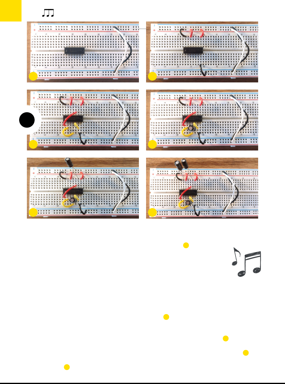
To make sure these rails are sharing electrons,
connect those on the top of the breadboard to
those on the bottom (positive to positive, and
negative to negative). It should look something
like the right side of Figure A.
Next, connect pins 14, 12, and 8 to a positive
voltage rail (+), and pin 7 to a ground rail (–), as
shown in Figure
B
.
2. CONNECT THE LOGIC PINS
Now make the internal chip connections, as
shown in Figure
C
:
• Pin 1 goes to pin 10
• Pin 2 goes to pin 4
• Pin 5 goes to pin 6
3. ADD THE CAPACITORS
Take a 1µF capacitor and place the long leg (aka
the anode, or positive terminal) into the row
shared by pin 3, and the short leg (the cathode,
or negative terminal) to the row shared by pin 6
(Figure
D
).
Our next capacitor is of the 0.1µF varietal. Put
the positive leg into the row shared by pin 9, and
the negative leg to ground (Figure
E
).
Our final capacitor is 10µF. It sits between pin
13 (long leg) and ground (short leg) (Figure
F
).
4. ADD THE POTENTIOMETERS
Now for the pots. You’ll attach your first
DIY USIC: The Undertoner Synth
54 makezine.com
Dogbotic Labs, Maisy Byerly (maisybyerly.com)
A B
D
F
C
E
M85_052-57_SS_BEx_Undertoner_F1.indd 54M85_052-57_SS_BEx_Undertoner_F1.indd 54 4/10/23 3:52 PM4/10/23 3:52 PM
..................Content has been hidden....................
You can't read the all page of ebook, please click here login for view all page.