
4
Non-Linear Applications of Op Amp
Objectives
To learn the concepts for the use of operational amplifier in the following systems:
- Voltage comparator.
- Two applications of comparator as window detector and zero crossing detector.
- Schmitt trigger circuit with the extension of regenerative comparator.
- Multivibrator circuits.
- Precision rectifier or super diode with the combination of op amp as voltage follower and a diode.
- Extension of precision rectifiers for the use of peak detector circuits.
4.1 INTRODUCTION
- Comparator circuits designed for ‘specific purpose’ or application work faster than op amps designed with general purpose applications. Input voltages to comparator circuits are analog signals and output is a digital or binary signal. The comparator circuits are mostly used in analog to digital conversion and signal conditioning circuits.
- Schmitt trigger circuit works on regenerative comparator principles. The applications of operational amplifiers as multivibrators are also covered.
- Precision rectifier is a combination of operational amplifier and a simple diode. It works as an ideal diode in the process of converting alternating signals into unidirectional voltages.
- By adding storage capacitor and MOSFET switch to precision rectifier, peak voltage detector circuits can be designed. Peak voltage detector circuits find many applications in industrial control circuits and battery level detector circuits in battery operated systems.
4.2 VOLTAGE COMPARATOR
Simple circuit of voltage comparator is shown in Fig. 4.1. It uses an operational amplifier (voltage amplifier) in open-loop conFiguration with two input voltages V1 and V2 and one output voltage Vout. Op amp increases the magnitude of input signal with voltage gain AV.

Fig. 4.1 Comparator Circuit with Input Voltages and Output Responses
Comparator Circuit Operation
- The comparator circuit compares the two input voltages V1 and V2 and produces an output voltage, whichever is larger or smaller between the two voltages.
- If the non-inverting input voltage V1 (or V+ ) is greater than the inverting voltage V2 (V−), output voltage becomes or makes transition (jumps) to the maximum positive voltage + VCC (+VSat) in the device.
- If the non-inverting input voltage V1 (or V+ ) is less than the inverting voltage V2 (V−), output voltage becomes or makes transition (jumps) to the largest negative voltage − VCC (−VSat) in the device.
Comparator Circuit with Input Voltages and Output Responses
Comparator circuit has non-linear behaviour, switching the device between highest positive or negative voltages as shown in Fig. 4.1 (a) and (b). The inputs to comparator circuit are ‘analog signals’ and its output is a ‘digital signal’ whether high or low. The nature of digital output depends upon the magnitudes of comparing voltages at the input port of operational amplifier.
- Some applications of comparator circuits are (a) analog to digital (A to D) converter and (b) signal conditioning circuits.
- ‘Precision and low noise operational amplifiers’ are used for conditioning the signals from transducers such as light, heat, and temperature sensors before they are fed to analog to digital conversion circuits.
4.3 OP AMP VOLTAGE COMPARATOR
Comparator circuits basically use operational amplifiers (op amp). One of the two input voltages to op amp is considered as reference voltage Vref and the second input is considered as input voltage Vin, as shown in Fig. 4.2. Therefore, the expressions for output voltage Vout and voltage gain AV are as follows:

Fig. 4.2 Voltage Comparator Circuit Using Operational Amplifier
Op amp voltage gain
![]() (4.1)
(4.1)
∴ Comparator output voltage is expressed as in the following:
Vout = AV (Vin − AV· Vd(4.2)
where differential input voltage can be given as follows:
Vd = (Vin − Vref)(4.3)
Input signals are direct coupled to the input terminals of operational amplifier. The op amp is a differential amplifier working with differential input voltage Vd and high voltage gain AV.
Example 4.1
An operational amplifier in open-loop conFiguration working as a differential amplifier shown in Fig. 4.2 has voltage gain AV = 104. Supply voltage VS = ±15 V. Calculate the output voltages for the differential input voltages (a) Vd (1) = 0.25 V and (b) second input Vd (2) = 0.5 mV.
Solution: Voltage gain AV = 104 and op amp supply voltage VS = ±15 V.
The saturation level of output voltage VSat = ± VS ± 1 V = ± 15 V ± 1 V = ±14 V
Op amp output voltage Vout (1) = AV × Vd (1) = 104 × 0.25 V = 2500 V. However, the output voltage will be only at VSat = 14 V.
Op amp output voltage Vout (2) = AV × Vd (2) = 104 × 0.5 × 10−3 V = 5 V.
Then, the output voltage will be at Vout = 5 V.
Circuit Analysis and Operation of Electronic Voltage Comparators
An electronic voltage comparator compares two (input) voltages and produces an output voltage, whichever is larger among the two input voltages. The comparator output has two output levels high or low as shown in Fig. 4.4. They are used in analog to digital (A to D) and digital to analog (D to A) converter circuits. Simple comparator circuit uses an operational amplifier, which is shown in Fig. 4.1.
- It has two input voltages V+ and V−. These two input voltages are compared with one another and output voltage will be equal to larger of the two inputs.
- Output voltage assumes only one of the two values (−VSat), as shown in Fig. 4.4 and Fig. 4.5. The output signal will be high or low representing digital or binary value.
- Output voltage will be high (+VSat) if V+ is larger than V−.
- Output voltage will be low (−VSat) if V+ is less than V−.
- Polarity of the comparator’s output voltage depends upon the polarity of the difference voltage Vd (differential input voltage), as shown in Fig. 4.1.
- Transfer characteristic (input−output curve) of the comparator is shown in Fig. 4.2.
- Input−output curve crosses the origin when V+ is equal to V−
Simple comparator circuit using op amp is shown in Fig. 4.3.

Fig. 4.3 Voltage Comparator Circuit Using Operational Amplifier
Comparator circuits are of two types (see Fig. 4.4 and Fig. 4.5)

Fig. 4.4 (a) Non-Inverting Comparator Circuit; (b) Transfer Characteristic (Input–Output Curve)

Fig. 4.5 (a) Inverting Comparator Circuit; (b) Transfer Characteristic (Input–Output Curve)
- Non-inverting comparator.
- Inverting comparator.
Non-inverting comparator: When the input signal to a comparator circuit is greater than a certain minimum voltage (transition/threshold) level, the output voltage will be in high state for a non-inverting comparator circuit.
4.3.1 Non-inverting Comparator
Basic non-inverting comparator circuit with its transfer characteristic is shown in Fig. 4.4 (a) and 4.4 (b). Assume an op amp in open-loop conFiguration, as shown in Fig. 4.4 (a), to understand its operation as a comparator.
Output response: Output response of comparator circuit is shown as transfer characteristic relating the input and output voltages. It has two horizontal lines. The first level represents high output corresponding to (−VSat) as shown in Fig. 4.4 (b). It is a non-linear characteristic. Expressions for voltage gain and input voltage are as follows:
Amplifier gain is expressed as follows:
![]() (4.4)
(4.4)
Input voltage is given as in the following:
![]() (4.5)
(4.5)
Consider voltage gain of op amp AV = 104 (voltage gains AV will be of the order of 103−105) and maximum value of Vout = 14 V, when the supply voltage VCC = 15 V.
From the data, the input voltage ![]()
Thus, the difference between non-inverting voltage V+ and inverting voltage V− is 1.4 mV.
- If a non-inverting input signal larger than 1.4 mV is applied to the op amp, output voltage Vout becomes 14 V (+VSat) by comparing with the existing level of other input voltage with the applied input signal.
- In Fig. 4.4 (b), the values for −VSat are given as 15 V to indicate that the maximum level of saturation voltage the op amp output can reach under ideal conditions.
4.3.2 Inverting Comparator Circuit
Basic inverting comparator circuit with its transfer characteristic is shown in Fig. 4.5 (a) and (b). If an inverting input signal larger than 1.4 mV is applied to the op amp, output voltage Vout becomes −14 (− VSat) by comparing the existing level of input voltage with the applied input signal.
These transitions among output voltages (+VSat and −VSat) for input voltages (see Fig. 4.5) suggest that an operational amplifier works as ‘comparator’ circuit.
The definition of comparator can be framed from the previous discussions:
- Voltage at one of the inputs of comparator op amp compares with the voltage at the second input terminal and produces high voltage if it is larger than the second voltage.
- The second voltage used as reference is also known as ‘reference voltage’.
- If reference voltage Vref is zero, the transfer characteristic passes through origin as shown in Fig. 4.5(b).
- If the reference voltage has a finite voltage larger than the minimum required level for transitions, the transfer curve will not pass through origin but shifts away from the origin, which is equal to Vref. It is also known as ‘threshold voltage VT’.
- Voltage at one of the inputs of comparator op amp compares with the voltage at second input terminal and produces low voltage if it is less than the second voltage.
- Saturation voltages +VSat and −VSat are shown as 15 V at which the output response can attain its maximum saturation under ideal conditions. However, practical situation has slight deviations.
4.4 DIFFERENT TYPES OF COMPARATOR ICS
Single voltage comparator ICs: LM 311, LM 111-N, LM211-N.
Some specifications and features as follows:
- Supply voltage to ICs = 5 V.
- Differential input voltage: ± 30 V.
- Power consumption: 135 mW at ± 15 V.
- Less susceptible to spurious oscillations because of stable power supply.
- Less speed of operation.
The applications of LM 311 (see Fig. 4.6) are as follows:

Fig. 4.6 Single Voltage Comparator IC LM 311
- Driver for lamps or LEDs and relays. It can drive TTL or DTL ICS.
- Zero crossing detector for magnetic transducer.
- Low-level photodiode detector.
Dual Comparator IC LM393 (see Fig. 4.7)

Fig. 4.7 Dual Comparator IC LM 393
Quad Voltage Comparator IC LM 339 (see Fig. 4.8)

Fig. 4.8 Quad Voltage Comparator IC LM 339
- Comparator ICs such as LM 339, LM 393, and LM 311 comparator ICs work on single or dual power supply voltages. Maximum supply voltage is 32 V.
- Four comparators are embedded in a single pack with low cost. Therefore, this IC is preferred in industrial applications with low budget applications.
Definition of Hysteresis: Hysteresis means deficiency or lagging behind. It was adopted from a Greek word by Alfred Ewing to describe the behaviour of magnetic materials. Hysteresis is the characteristic feature of materials, whose behaviour depends upon its present and previous environments. The concept is extended to electronic systems. The current state of a system depends upon its internal or previous state and history in the system. Further, the future state of the system can be predicted from its present history in the system, depending upon the nature of inputs.
One of the latest applications is the introduction of ‘Hysteresis’ in computer operations during the ‘Graphical User Interface’ (GUI) to simplify the system operations in most efficient way by system users. Computer system working should adapt to the user operations. Visual effects in the system should match to the user operations in simple ‘user-friendly’ functionality.
The desired amount of hysteresis is added in electronic circuits to reduce noise due to bouncing operations between switching operations by introducing delay in electronic switches.

4.5 COMPARATOR APPLICATIONS
Comparator is normally used in applications where some level of a varying signal is compared to a fixed magnitude of voltage reference Vref.
- Platinum RTD thermometer to measure 0°C to 500°C.
- Exponential voltage to frequency converter for electronic music synthesizers.
- Window comparators are used in temperature control circuits.
4.5.1 Window Detector
Basic principle: A simple comparator determines whether one of its input voltages is higher than the other voltage. However, the method of identification of a region between two threshold levels of unknown (input) signal voltages can be done by a circuit known as window detector.
Window detector determines whether a signal lies within a desired range of values.
Window Detector (Comparator Circuit Application)
Window detector is a special type of comparator circuit, which identifies the desired range of voltages at its input. It consists of two operational amplifiers (operational amplifier-1) and (operational amplifier-2) operating together and two diodes (D1 and D2) connected as shown in Fig. 4.10. There are three input terminals. Two input terminals are meant for reference voltages and third input terminal is for input signal.
There are two reference voltages Vref (high) and Vref (low) and the input signal voltage Vinput whose range of signal has to be estimated. One output voltage is considered for the prediction of the input signal status whether it lies or stays in the specified range (window) or outside the desired range.
There are three voltage input points:
- Vref (high)
- Vref (low)
- Actual input signal Vinput
Reference voltages Vref (high) and Vref (low): The two reference voltages correspond to two threshold voltage levels. They define the two voltage levels of the desired range (window) of voltages of a signal. Voltage Vref (high) corresponds to upper level (threshold) of the signal. It is similar to ‘upper trigger level’ (UTP) of Schmitt trigger circuit. Similarly, voltage Vref (low) corresponds to low level (threshold) of the signal. It is similar to ‘low trigger level’ (LTP).
If input voltage Vinput is lower than the higher reference voltage Vref (high), output voltage Voutput will be ‘positive voltage’. Similarly, if the input voltage is higher than lower reference voltage Vref (low), output voltage will be ‘positive’. Thus, the output of window detector will be positive within a range of ‘two threshold voltages’ in a signal waveform. Thus, a window detector identifies the known range of input signal within ‘two threshold levels’.
If the input signal (voltage) is below the lower reference voltage Vref (low) output voltage will be zero. If the input voltage is above the higher reference voltage Vref (high), output voltage will be zero. Such points of operation can easily be understood from input and output signal conditions shown in Fig. 4.9 and Fig. 4.10.

Fig. 4.9 Window Detector (Input and Output Signal Waveforms)

Fig. 4.10 Window Detector (Comparator) Using Two Op Amps and Two Diodes
Tripping points (lower and upper): From the discussion, we can identify a signal within a range of two voltages. The two voltages are considered as two threshold voltages, which in turn correspond to lower tripping point (LTP) and upper tripping point (UTP) considered in the operation of Schmitt trigger circuit.
Comparator output voltages: For input signal voltages, within the specified two threshold voltages, the window comparator output has one type of voltage say ‘X’. Then, for input signal voltages that lie outside the specified range, the window detector output will be different from ‘X’.
Circuit description: Window detector circuit has two operational amplifiers (741 op amps) (op amp-1 and op amp-2) and two diodes connected as shown in the circuit of Fig. 4.11. In this circuit, Vref (high) has been interchanged as Vref (low) and Vref (low) has been interchanged as Vref (high). Then, the circuit produces opposite type of output signal to the previous circuit. It means that the output voltage will be the negative voltage.

Fig. 4.11 Window Detector Using Two 741 IC Op Amps and Two Diodes
4.5.2 Zero Crossing Detector
Comparator circuits can be used with zero threshold voltage, that is, VR = 0. The comparator detects and marks voltage level transitions at zero reference crossings of input signal voltage. Then, the comparator circuit is known as ‘zero crossing detector’.
- Sine wave signal is represented with voltage (on Y-axis) and time (on X-axis).
- Zero voltage point crossings occur, when the sine wave function changes from positive to negative voltages and at the times of negative to positive voltage transitions across the time axis. Signal crosses through zero voltage points two times in a cycle of sine waveform. Such points are called as ‘zero crossing points’, as shown in Fig. 4.13 (a).
- ‘Zero crossing detector’ detects the points of crossing zero voltage, while any signal makes transitions from (a) positive to negative voltage or (b) negative to positive voltage. Thus, in a sinusoidal signal, there will be two ‘zero crossing points’ as shown in Fig. 4.13(a).
- Simple circuits to understand zero crossing detector or comparator circuits are shown in figs 4.12 and 4.13.

Fig. 4.12 (a) Zero Crossing Detector with Positive Input Voltage; (b) Zero Crossing Detector with Negative Input Voltage

Fig. 4.13 (a) Input Sine Waveform; (b) Output Waveform
Sine wave input signal is applied to non-inverting (NIV) input terminal in Fig. 4.12 (a) and zero reference voltage is maintained at (−) inverting terminal (INV). Then, the output waveform with the detection of zero crossings for NINV input voltages is shown in Fig. 4.13(b).
Zero crossing is the point where the voltage is zero on a waveform. Zero crossing points in a sine wave are shown in Fig. 4.13 (a), points 1 and 2 for one (sine wave) cycle.
Zero crossing detector wave forms for inverting input voltages are shown in Fig. 4.14 (a) and (b).

Fig. 4.14 (a) Input Sine Waveform to Zero Crossing Detector; (b) Output Square Waveform
Sine wave input signal is applied to inverting (INV) input terminal in Fig. 4.12 (b) and zero reference voltage is maintained at (+) non-inverting terminal (NIV). Then, the output waveform with the detection of zero crossings is shown in Fig. 4.14.
Zero crossing is the point where the voltage is zero on a waveform. The zero crossing points in a sine wave are shown in Fig. 4.14 (a).
Applications
- The fundamental frequency of speech is detected by counting the number of ‘zero crossings’ in a speech signal in speech recognition systems. The fundamental frequency of adult male speech ranges from 85 to 180 Hz, whereas the fundamental frequency of adult female speech ranges from 165 to 255 HZ.
Typical values of fundamental frequencies are 120 Hz for men and 210 Hz for females. With age, these values change. Doctors may advise the patients suitably for the reduction in speech sound based on fundamental frequency measurements.
- During the transmission of digital signals on analog channel (AC) in modem circuits.
- The detection of amplitude and zero crossings during the conversion of digital values into binary data in digital communication systems.
- Image processing techniques, where digital signal of an image passes through a set of preset-zero values.
- Digital audio.
- Comparators are mostly analog ICs after operational amplifiers.
Some important specifications on data sheets of comparator ICs for circuit design are as follows:
- Propagation delay (speed) TPD: The voltage level comparisons of analog signals need a minimum amount of time between time T1, when the input signal crosses the reference voltage Vref and time T2 when the output voltage crosses 50% of the supply voltage VCC.
- Slew rate (rise and fall times of signal responses defining the speed of the device).
- Bandwidth: It relates to the maximum frequency range of input signals that can be operated with the system. For high frequency signal operation, operational amplifier with large bandwidth has to be considered.
- Voltage gain: It is the total device amplification between input and output signals.
- Current consumption for power dissipation considerations.
- Input off-set voltage V10: It is differential input voltage for device operation without going to false switching between voltage levels.
- Input common mode voltage range VICM: The range of input voltages to be maintained by both the inputs for regular function of the comparator.
- Common mode rejection ratio (CMRR).
- Supply voltage rejection ratio (SVR).
4.6 SCHMITT TRIGGER (REGENERATIVE COMPARATOR)
Schmitt trigger name has two words: (a) Schmitt and (b) trigger.
Schmitt is the name of the inventor and trigger means that the output voltage remains constant until the input voltage changes sufficiently to trigger changes in voltage levels.
Otto Herbert Schmitt, American Scientist and Engineer (1913−1998) invented the following circuits: (a) Schmitt trigger (b) cathode follower (c) differential amplifier, and (d) chopper stabilized amplifier.
Schmitt trigger circuit is generally used in signal conditioning applications:
- To remove noise from signals.
- To convert sine waves into square waves.
- To obtain digital output (signal wave shape) by suitable selection of two ‘threshold voltage levels’ for any type of analog input signal waveform.
- Digital circuits.
- Squaring circuit.
- Amplitude comparator circuit.
Schmitt trigger circuit uses positive feedback for its operation. It has two levels of transitions in its output voltage with suitable threshold voltage levels in its input voltages. They are known as follows:
- Upper threshold point (UTP), where the output voltage makes transition from low to high voltage level for a suitable level of ‘trigger’ initiated by input voltage. For UTP, the input voltage should be higher than the chosen ‘threshold voltage’.
- Lower threshold point (LTP), where the output voltage makes transition from high to low voltage level for a suitable level of ‘trigger’ initiated by input voltage. For LTP, the input voltage should be lower than the chosen ‘threshold voltage’.
- During the two transition levels, the output voltage remains constant.
Thus, the Schmitt trigger has dual thresholds. Dual threshold action is considered as possessing ‘Hysteresis’. The two stable states in the output voltage suggest that the behaviour of Schmitt trigger circuit is similar to bistable multivibrator or flip-flop.
Schmitt Trigger circuit can be understood as a comparator (differential amplifier) with positive feedback (loop gain greater than one). Positive feedback is introduced by using two resistors R1 (RF) and R2 as shown in Fig. 4.17. A part of output voltage is feedback to input voltage using the two resistors R1 (RF) and R2 (voltage divider circuit).
Schmitt Trigger uses the following concepts of (UTP) and (LTP):
- Upper Trigger or Threshold point (UTP)
- Lower Trigger or Threshold point (LTP)
Unsymmetrical or symmetrical output signal waveforms can be obtained using suitable design and selection of UTP and LTP. Block diagram is shown in Fig. 4.15.

Fig. 4.15 Conversion of Sine Wave (Input) into Square Wave (Output Signal) by Schmitt Trigger Circuit
The layout of transistor Schmitt trigger circuit is shown in Fig. 4.16. Circuit has the following components:

Fig. 4.16 Schmitt Trigger Circuit Using Transistors to Generate Square Waveform from a Sine Waveform
- Two transistors.
- Biasing resistors RC1, R1, and R2/1
- Timing circuit R1 and C1.
- Feed back and DC bias stabilization providing resistor RE.
- Output voltage of the first transistor T1 is connected to the base terminal of T2.
- DC power supply voltage VCC.
There are two conditions of operations for bistable multitype of operation using UTP and LTP concepts in the Schmitt trigger circuit:
- Transistor T2 is in ON state, while the transistor T1 is in the OFF state.
- Transistor T1 is in ON state, while the transistor T2 is in the OFF state.
- Upper threshold voltage

- Lower threshold voltage

4.7 INVERTING SCHMITT TRIGGER
Schmitt trigger circuit using operational amplifier and positive (regenerative) feedback.
Inverting Schmitt trigger circuit using op amp is shown in Fig. 4.17.

Fig. 4.17 Inverting Schmitt Trigger Circuit Using Op Amp and Regenerative (Positive) Feedback
Circuit description: Inverting Schmitt trigger circuit consists of the following components:
- Operational amplifier (op amp).
- Dual power supply to provide + V and − V voltages to op amp terminals on IC.
- Input signal source (function generator) to provide sine wave of desired amplitude and frequency (function generator with negligibly low internal resistance).
- Cathode ray oscilloscope (CRO) to observe and measure input and output signals.
- Resistors R1 and R2 provide positive (regenerative) feedback to fix the upper threshold point and lower threshold points to determine output wave shape.
Input voltage Vin (sine wave) from a signal (function) generator or beat frequency oscillator (BFO) is applied to negative (−) (inverting) input terminal of operational amplifier preferably μA 741. Feedback voltage VF (VY) is applied to the non-inverting input (+) terminal of op amp through the resistor R1 (RF). The feedback voltage VF = βVout, where ![]() . Then
. Then ![]()
Between voltage levels defined by upper threshold point (UTP) and lower threshold point (LTP), points of input sine wave signal amplitudes, clamping of output signal waveform occurs, so that output is a square waveform.
Thus, it works as an excellent voltage level detector with fast switching actions.
Positive feedback in Schmitt trigger circuits: Consider small magnitude of positive voltage Vin at the inverting input terminal (1) of the op amp. It is amplified and produces increased negative output voltage at the output terminal (3).The voltage divider R1 (RF) and R2 feeds a part of negative output voltage to the non-inverting input terminal (2).
The feedback voltage VF = β Vout where ![]() . It is amplified and feedback to the input port. This regenerative action continues till the output voltage Vout reaches Vout (max) = VCC = − VSat (negative saturation voltage). Output voltage will be held in the ‘low state’ of value VCC = − VSat.
. It is amplified and feedback to the input port. This regenerative action continues till the output voltage Vout reaches Vout (max) = VCC = − VSat (negative saturation voltage). Output voltage will be held in the ‘low state’ of value VCC = − VSat.
Thus, output voltage level − V (negative saturation voltage) is obtained through regenerative action (positive feedback) in comparator. Such action suggests that the ‘Schmitt trigger works as regenerative comparator’.
On similar lines, it can be understood that for small values of negative input voltages, regenerative comparator action due to positive feedback causes output voltage to be held at VCC = + VSat. Finally, output voltage will be held at ‘high state of value VCC = + VSat’.
Schmitt trigger is similar to bistable multivibrator circuit: It is used for converting analog signals into digital signals using the concepts of UTP and LTP.
The analysis of input and output voltage levels to determine UTP and LTP Schmitt trigger is as follows:
- When the input voltage to inverting input terminal Vin = 0 V, assume the maximum level of output voltage Vout (max) = VCC = + VSat.
- Then, the non-inverting input voltage
 .
. - As the input voltage goes on increasing, at a trigger (threshold) voltage level of magnitude
 , the output voltage makes a sudden transition or jump to −VSat. Then, the transition is defined to take place (occur) at upper threshold (trigger) point (UTP) at voltage V1.
  .
.- Then, the output voltage Vout (max) = VCC = − VSat.
- Second (another) transition occurs when the input voltage Vin reduces below

- Voltage V2 at LTP =
 .
. - Then, the output voltage changes (switches) from − VSat to + VSat/1

Fig. 4.18 Input and Output Waveforms of Operational Amplifier
Change in voltage levels from UTP to LTP is due to hysteresis in the transfer curve for Schmitt trigger circuit performance. Hysteresis voltage ![]() .
.
Transfer Characteristic to Explain Hysteresis in Schmitt Trigger Circuit
Transfer characteristic of Schmitt trigger is a graph between the input voltage and its output voltage response. The analysis of voltages for input and output signals are also shown using hysteresis loops. Figure 4.19 (a) shows the sudden transition of output voltage Vout from + VSat to VSat, when the input voltage (Vin) exceeds V1 (VUTP). This shows input and output transitions at UTP.

Fig. 4.19 (a) UTP (b) LTP (c) Total Hysteresis Loop of Inverting Schmitt trigger
Figure 4.19 (b) shows the sudden transition of output voltage Vout from − VSat to + VSat, when the input voltage (Vin) exceeds V2 (VLTP). This shows the input and output signal transitions at LTP.
Figure 4.19 (c) shows the transitions of output voltage Vout from − VSat to + VSat and vice versa at both UTP and LTP points. It shows the composite or total hysteresis loop characteristics during UTP and LTP transitions over a cycle of variations.
4.8 WAVE SHAPING OF OUTPUT SIGNAL USING ADJUSTABLE LTP AND UTP
Irrespective of the nature of repetitive input (analog) signal, Schmitt trigger converts them into square wave signals. It is achieved with adjustable LTP and UTP points of the device operation.
With the previous circuit in Fig. 4.17, UTP and LTP voltages are symmetrical about the origin ‘O’ on the transfer characteristic of the hysteresis loop. Using two semiconductor diodes and adjustable (variable) resistors, (Fig. 4.20) UTP and LTP points can be shifted to desired levels to modify the points of transitions in the output waveforms.


Fig. 4.20 (a) UTP (b) Adjustable LTP and (c) Composite Hysteresis Loop of Inverting Schmitt Trigger
Assuming initial output voltage level as +VSat, output voltage in the output waveform can be seen as ![]() .
.
4.9 NON-INVERTING SCHMITT TRIGGER
Non-inverting Schmitt trigger circuit is shown in Fig. 4.21. Input current Iin through op amp input port will be negligible, that is, Iin ≅ 0. Practically, Iin ≅ IB ≅ 200 nA (max).

Fig. 4.21 (a) Non-Inverting Schmitt Trigger Circuit (b) Hysteresis Loop
However, the current through R2 will be equal to current I1 through R1. Then, VR1 = VR2
which means ![]()
Therefore, 
As the input terminal (2) shown in Fig. 4.21 is at virtual ground potential, (voltage across R2) ![]() = Vin (input voltage at non-inverting input terminal).
= Vin (input voltage at non-inverting input terminal).
If the op amp is in lower state (voltage across R1), VR1 will be equal to the output voltage, − VSat at the initial state of transition. Therefore, initially VR1 = −VSat.
At lower threshold point (LTP) ![]() .
.
Therefore, ![]() .
.
As the input voltage increases, sudden jump or transition takes place from −VSat to +VSat.
Then, ![]() at UTP.
at UTP.
VSat to −VSat at LTP, the voltage level is
![]() at LTP.
at LTP.
Hysteresis voltage 
4.10 ADJUSTABLE UTP/LTP SCHMITT TRIGGER
UTP and LTP can be individually adjusted using the non-inverting Schmitt trigger circuit shown in Fig. 4.22 (a) and (b).

Fig. 4.22 (a) Non-inverting Schmitt Trigger Circuit Using Adjustable UTP and LTP (b) Hysteresis Loop
Adjustable Schmitt trigger circuit consists of the following electronic components in the circuit:
- Input signal source.
- Operational amplifier.
- Two diodes (rectifier devices) D1 and D2.
- Three resistors R1, R2, and adjustable resistor RA.
- Cathode ray oscilloscope (CRO).
In the non-inverting Schmitt trigger circuit in Fig. 4.22 (a), there are two types of signal feedbacks from the output to the non-inverting input terminal through two diodes D1 and DA For positive and negative outputs, diode D1 conducts during negative output (− VSat) and diode DA conducts for positive output (+ VSat).
At UTP, required input voltage ![]()
At LTP, required input voltage ![]()
Threshold voltage
Example 4.2
Draw the output signal waveform of non-inverting Schmitt trigger circuit using op amp with the following data:
- Supply voltage VCC = ± 15 V.
- Saturation voltage levels (−VSat) = −14 V.
- Input signal VJN = Vm sin (ω t) 4 sin (ω t)
- R1 = 22 K and R2 = 2.2 K
Solution: Upper threshold voltage V1 at UTP = ![]()
Lower threshold voltage V2 at LTP ![]()
- Output voltage makes transition to +VSat = −14 V, when the input voltage exceeds + 1.4 V at UTP.
- Output voltage stays at +14 V till the input signal reduces to V2 = −1.4 V at LTP. Then, it suddenly jumps or drops to voltage −VSat = −14 V.
- Output voltage stays at +14 V till the next transition to + VSat again at second UTP at second cycle of sine wave input signal.

Fig. 4.23 Hysteresis Loop
Schmitt Trigger Circuit Using 555 IC Timer
Schmitt trigger function can be realized with 555 IC. 555 IC was designed and introduced by Hans CamenZind in 1971 at Signetics company, USA. It was later acquired by Philips. It has timer and oscillator applications.
The basic principles of 555 IC timer use as Schmitt trigger circuit is shown in Fig. 4.24.

Fig. 4.24 (a) Block Diagram Concept of Schmitt Trigger Circuit Using 555 Timer IC. (b) Input and Output Waveforms Using the Concept of UTP and LTP Threshold Voltage Levels
Schmitt trigger circuit operation: Input signal Vin, for example, a sine wave is applied between the input pair of terminals (5) and (1) of 555 IC, as shown in Fig. 4.24. When the input signal voltage rises slightly above the UTP shown as voltage V1 in Fig. 4.24 (b), the trigger action begins and the comparator output becomes high as shown in Fig. 4.24 (b) across the terminals (3) and (1) of 555IC. It is shown as point (1) on the output square wave.
![]() is the UTP voltage level. At a later stage, if input voltage Vin goes on decreasing, the 555 IC timer output remains constant (without undergoing any change from the previous high value), until the input voltage reduces to a value below V1 that corresponds to LTP. It is shown as point V2 on the output waveform in Fig. 4.24 (b). It is marked as point (2), where output is triggered to change (makes transition) to a low value.
is the UTP voltage level. At a later stage, if input voltage Vin goes on decreasing, the 555 IC timer output remains constant (without undergoing any change from the previous high value), until the input voltage reduces to a value below V1 that corresponds to LTP. It is shown as point V2 on the output waveform in Fig. 4.24 (b). It is marked as point (2), where output is triggered to change (makes transition) to a low value.
![]() is the LTP voltage level.
is the LTP voltage level.

Fig. 4.25 Typical Schmitt Trigger Circuit Using IC 555
Such output function of 555 IC will be similar to Schmitt trigger behaviour. Output remains constant between UTP and LTP threshold voltage levels. Hysteresis is the voltage range between the two voltage levels V1 and V2. Maintaining V1 always higher than V2, adjustable hysteresis with desired points of UTP and LTP can be realized in the Schmitt trigger behaviour.
- Name of 555 IC is suggested due to the use of three resistors (5 kΩ) inside IC 555.
- 556 IC is 14-pin dual package containing two 555 ICs.
4.11 MULTIVIBRATORS
There are three types of multivibrator circuits. They are as follows:
- Astable multivibrator: It is known as free running oscillator or square wave generator.
- Monostable multivibrator: It is referred as ‘one shot’ multivibrator.
- Bistable multivibrator: It is popularly known as ‘flip-flop’ circuit.
4.11.1 Astable Multivibrator
Astable Multivibrator Circuit Using Operational Amplifier
Introduction:
- Astable multivibrator produces square-wave output signal. It is also known as free running oscillator, because the multivibrator does not require any external trigger input signals to change states in output square wave signal waveform.
- Astable multivibrator output has two quasi-stable states. The output switches between positive and negative saturation level voltages ±VSat. No external trigger signal is required to produce changes in levels ±VSat of output voltage waveform.
- The concepts of positive feedback, hysteresis, UTP, and LTP are used in the circuit with an addition of a capacitor at the input port of the operational amplifier shown in Fig. 4.26. Charging and discharging cycles of ‘capacitor C’ through the ‘feedback resistor RF’ forces the output to swing between the charging positive voltage level − VSat (equal to supply voltage − VCC or VS). Such voltage swings produces free running square wave output without any external inputs. The frequency of output waveform will be decided by ‘RC time constant’ (RF · C).
- Time period of the output signal waveform
 .
. - Frequency of output signal

Astable Multivibrator Circuit
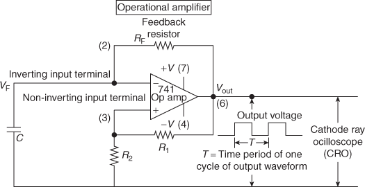
Fig. 4.26 Astable Multivibrator Circuit Using Operational Amplifier
Op Amp Multivibrator Circuit:
- Op amp multivibrator circuit are very simple to design, construct and use them in a user friendly way. By simply turning ‘ON’ the Astable Multivibrator, the circuit functions as free running oscillator generating square-wave output signal. It can be used when a simple square wave is required.
- Op amp Astable Multivibrator circuit consists of the following components:
- one operational amplifier
- three resistors RF, R1, and R2, and
- one capacitor ‘C’.
- It has two operations embedded in the circuit function:
- Feedback from output terminal to capacitor ‘C’ is provided by the feedback resistor RF.
- Presence of hysteresis (to maintain the two threshold states of operation of LTP and UTP) is provided by the two resistors R1 and R2.
- Circuit design:
- Assume required frequency ‘f’ of square wave to get from ‘Astable Multivibrator’.
- Calculate the time period
 sec.
sec. - Choose the practical values of RF, C · R1, and R2 to satisfy following equation.
- (d) Frequency of output signal
f =

- (e) Observe the waveform using CRO to verify the design with estimated values.
- In computer circuits, logic gates function as decision making devices. Binary addition and subtraction are performed by logic gates. However, the presence of decision making circuits is not enough. During the logical addition and subtraction processes, memory devices are needed to do the total arithmetical functions. Such memory elements are realized by using multivibrator circuits known as flip-flop circuits.
- Op amp multi (multivibrator) has the advantage of providing higher output voltages equal to VCC or VS ranging from 12 to 15 V. While, multivibrator circuits using ‘logic gates’ provide a maximum output voltage equal to its supply voltage of 5 V.
4.11.2 Monostable Multivibrator
Monostable Multivibrator Circuit Using Operational Amplifier
Monostable Multivibrator is known as one-shot multivibrator. Output has one stable state and one quasi-stable state. Output will remain in stable state (Vout = + VS), (where VS = supply voltage to op amp) till the multivibrator receives a trigger input. Trigger input pulses are shaped into sharp (narrow) pulses by the R–C differentiator circuit consisting of capacitor C1 and resistor R3. The time constant R3 · C1 should be much less than the time period ‘T’ to produce narrow triggering pulses and avoid false transitions in states.

Fig. 4.27 Monostable Multivibrator Using Operational Amplifier
Once the sharp trigger pulse is applied at non-inverting input terminal (3) of op-amp, the output makes a transition to quasi-stable (temporary) state (Vout = − VS) for a specified (designed) time period ‘T’. The time period is decided by the R−C combination of C2 and RF. The diode D1 limits the positive amplitude of the trigger pulses. After the expiry of the time period, the output returns to the previous stable state, as shown in the output waveform in Fig. 4.27.
Op amp monostable multivibrator circuit in Fig. 4.27 has the following electronic components:
- Operational amplifier.
- Feedback resistor RF and timing capacitor C2 to determine the time period ‘T’ of output signal and its frequency.
- Diode D2 is connected in parallel to capacitor C2.
- Trigger pulse wave shaping circuit consisting of differentiator with elements C1, R3, and diode D1.
- Potential divider network consists of R1 and R2 to provide threshold voltage levels.
- Output waveform appears across terminal ‘6’ and common terminal.
4.12 PRECISION RECTIFIERS
4.12.1 Series Diode Half-Wave Rectifier (HWR) Circuit
Half-wave rectifier circuit has AC input signal with alternating half sinusoids. It allows only positive half sinusoids into the output signal. The negative half sinusoids are blocked by rectifier device.
Circuit components are as follows:
- Input signal source: sinusoidal signal (function generator/mains AC with step-down transformer): sinusoidal signal.
- Ideal diode (functions as rectifier).
- Resistor.
- Cathode ray oscilloscope (CRO to observe waveforms and measure amplitudes).
Working Principle:
- During the positive half cycle of input sine waveform, semiconductor diode is forward biased. However, the diode conducts and behaves as a closed switch with negligibly small forward resistance. Therefore, the output wave is similar to input signal shown in Fig. 4.29.
- During the negative half cycle of input sine waveform, diode is reverse biased. Diode does not conduct and behaves as open switch with zero IR ≅ 0 current in the circuit. Thus, the output voltage will be zero as shown in Fig. 4.29.
- In Fig. 4.28, the situation is explained for one cycle of input signal. The feature repeats and the output waveform consists of positive half sinusoids for each cycle of input signal waveform.
- Thus, the alternating input sine waveform appears at the output with half sinusoids in one (positive) direction only.
- Rectification is one of the important process in signal condition of electronic systems.

Fig. 4.28 Series Diode Half-Wave Rectifier (HWR) with Input and Output Signal Waveforms
4.12.2 Shunt Diode Half-Wave Rectifier
This is an another form of half-wave rectifier circuit.
Simple half-wave rectifier circuit (Fig. 4.29) has the following components:
- Input signal from a function generator (assumed signal for the concept of circuit working).
- Resistor ‘R’.
- Diode (connected in shunt path and works as a rectifier) ‘D’.
- Cathode ray oscilloscope to study the signal wave shapes and magnitudes.

Fig. 4.29 Shunt Diode Half-Wave Rectifier with Input Sine Waveform Output Waveform
During the interval 0 to π of the input sine waveform, input voltage is positive. Therefore, the semiconductor diode is reverse biased. Diode acts as an open switch. Further, the output voltage will be equal to the input voltage, which is a half sinusoid in this case. On the other hand, when the input voltage is a negative half sinusoid, during the interval π to 2π, the diode will be forward biased. When the diode acts as an closed switch, the output voltage will be zero.
Definition of rectifier: When the input voltage to a rectifier device has both positive and negative half sinusoids (cycles) (alternating signal), the output signal consists of positive half sinusoids only. It means that the output signal consists of voltage in one direction only. The diode thus passes the positive half wave signals and stops (blocks/does not pass) the negative half sine wave signals.
4.12.3 Precision Half-Wave Rectifier Using Non-Inverting Op Amp (Signal Processing Rectifier Circuits)

Fig. 4.30 Precision Half-Wave Rectifier Circuit
Precision rectifier is a combination of an op amp with diode. It works as an ideal diode and rectifier. It is also known as super diode. It is used in precision half-wave and full wave rectifier circuits.
Non-inverting precision half-wave rectifier circuit is shown in Fig. 4.31.

Fig. 4.31 Precision Half-Wave Rectifier Circuit (Diode Acting as Short Circuit During Positive Half Cycle of Signal)
- Input signal voltage from a transducer or function generator (sine wave).
- Operational amplifier (op amp connected as non-inverting operational amplifier).
- Diode (as rectifier) ‘connected in the feedback loop of operational amplifier’.
- Cathode ray oscilloscope (CRO) to observe the waveform and measurements.
Working operation of the circuit: Small signals (outputs of signal transducers in radio and TV, etc) are amplified by (non-inverting) operational amplifier. However, the semiconductor diode detects the amplified signal voltage. Signal conditioning for output signals of one type of polarity is achieved by rectifier diode.
- During the positive half cycle of the input signal, the diode is forward biased.
- Diode behaves as short circuit (negligibly small resistance path).
- The output voltage waveform will be similar to input signal waveform during positive half cycles. The circuit works as a voltage follower for positive half sinusoids.
Circuit behaviour during positive half cycle is shown in Fig. 4.31.
Thus, in precision rectifier circuit, the output voltage is equal to input voltage after the transmission of amplified signal through the rectifier during positive half cycle of input signal.
Necessity of precision rectifier circuit: Silicon diode has a threshold (cut-in) voltage of about 0.5 to 0.7 V. Therefore, diode cannot be used directly to detect small signal voltages less than 0.7 V. The output signals of transducers in radio and TV are some examples to demand the use of precision rectifier circuit that provides amplification (using op amps) to low voltage signals before detection by rectifier diodes. Such circuits are also known as ‘active rectifier (HW/FW) circuits’.
Circuit behaviour during negative half cycle is shown in Fig. 4.32.

Fig. 4.32 Precision Half-Wave Rectifier Circuit (Diode Acting as an Open Circuit During Negative Half Cycle or When Input Signal is Less Than Zero)
During the negative half of the input signal (when the input signal voltage is less than 0 V), diode is reverse biased. Thus, the diode behaves as an open circuit (see Fig. 4.32). The output signal will be 0 V.
Input and output signal waveforms of non-inverting precision half-wave rectifier circuit are shown in Fig. 4.33.

Fig. 4.33 Input and Output Signal Waveforms of Non-Inverting Precision Half-Wave Rectifier Circuit Using Non-Inverting Op Amp and Diode
Some applications of positive half-wave precision rectifier circuits:
- Increasing the input signal level.
- Modification of signal wave shapes.
In order to rectify high frequency signals, operational amplifiers with large bandwidth having large fT (transition frequency) and high slew rate are used. In practical applications to process the small amplitude signals, required amount of gain (amplification) in operational amplifiers is introduced; such circuit is shown in Fig. 4.34.

Fig. 4.34 Precision Half-Wave Rectifier Circuit (With Gain Introduced by Using Two Resistors R1 and R2 for Low Amplitude Signals)
Precision HWR Circuit with gain (decided by the ratio of resistors R1 and R2) is given as follows:
Voltage gain of op amp = ![]()
Op amp Gain ![]()
4.12.4 Precision Half-Wave Rectifier Circuit Using Inverting Op Amp Precision HWR Circuit Using Reversed Diode in Feedback Path
The working of the circuit using inverting precision half-wave rectifier is shown in Fig. 4.35.

Fig. 4.35 Precision Half-Wave Rectifier Circuit Inverting Op Amp
- Input signal (Vin) is applied to the input port of the operational amplifier.
- Op amp is connected in non-inverting mode of operation.
- Input signal is passed on to the output port of the operational amplifier ‘A’, during the interval ‘0 to π ’ interval of the input signal (or positive part of any signal).
- Therefore, the diode is reverse biased and it acts as an open circuit. Such circuit is shown in Fig. 4.36. Output voltage Vout ≅ 0 V.

Fig. 4.36 Inverting Precision Half-Wave Rectifier Circuit with Reverse Connected Diode (Diode Acting as an Open Circuit During Positive Half Cycle or When Input Signal is Less Than Zero)
- During the negative half cycle ‘π to 2π ’ interval, (or when the signal from any transducer is less than 0 V) signal is passed on to the diode.
- Thus, the diode is forward biased and it behaves as a short-circuit path and the output voltage follows the input voltage as voltage follower.
- Output voltage will be similar in wave shape to negative portions of input voltage Vin.
- Inverting HWR circuit (active HWR circuit) with diode as closed path is shown in Fig. 4.37.

Fig. 4.37 Inverting Precision Half-Wave Rectifier Circuit Rectifier Diode in Feedback Path (Diode Acting as Short Circuit During Positive Half Cycles of Signal)
The input and output signal waveforms of inverting precision half-wave rectifier circuit are shown in Fig. 4.38.

Fig. 4.38 Input and Output Signal Waveforms Inverting Precision Half-Wave Rectifier Circuit Using Non-inverting Op Amp and Reversed Diode
Precision Half-wave Rectifier Using ‘Two Diodes’ With Op Amp in Inverting Input ConFiguration.
The circuit in Fig. 4.39 consists of inverting operational amplifier, two diodes, and input signal source (sinusoidal signal). Inverting operational amplifier with diode D1 in its feedback path produces negative half sinusoids in one direction (rectifier action). Using the second rectifier diode D2, unidirectional positive half sinusoids (‘for negative half sinusoids’) are obtained from circuit in Fig. 4.39.
- During ‘0 to π ‘interval of positive half sinusoids of input signal ‘Vin’, diode D1 is forward biased. Therefore, it acts as a short circuit. The negative output voltage at point ‘Y’ (voltage drop across reverse-biased diode D1) reverse biases diode D2. Further, diode D2 acts as an open switch. Therefore, the output voltage is ‘0’ (zero) during ‘0 to π ’ interval of the output signal.
- During ‘π to 2 π ’ interval of negative half sinusoids of input signal ‘Vin’, diode D1 is reverse biased and it acts as an open circuit. Positive output voltage at point ‘Y’ (voltage drop across reverse-biased diode D1) forward biases diode D2. Therefore, diode D2 conducts and functions as short circuit. Further, output voltage Vout is during ‘π to 2 π ’ interval of the signal consists of positive half sinusoid.
- Above explained operation repeats for all the other cycles of the signals as shown in Fig. 4.39.
The input and output waveforms of precision HWR with diodes are shown in Fig. 4.39. This circuit provides positive half sinusoids during the negative half cycle intervals of signals.
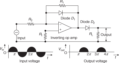
Fig. 4.39 Precision Half-Wave Rectifier Using Two Diodes
4.12.5 Precision Full-wave Rectifier (Absolute Value Circuit)
Precision full-wave rectifier circuit is shown in Fig. 4.40. Input signal to full wave rectifier is a sine wave consisting of positive and negative half sinusoids. This signal is processed by two op amps, two diodes, and a few resistors. The output waveform consists of all unidirectional positive half sinusoids. Thus, alternating positive and negative half sinusoids appear as unidirectional positive half sinusoids.

Fig. 4.40 Precision Full Wave Rectifier Circuit
When the input signal is going through positive half sinusoids, diode D1 is forward biased and hence it behaves as a short circuit. The output voltage of first op amp goes negative and reverse biases diode D2. Hence, diode D2 acts as an open circuit. Therefore, the equivalent circuit will be as shown in Fig. 4.41.

Fig. 4.41 Equivalent Circuit of Precision Full Wave Rectifier Circuit
The output voltage of first op amp ![]()
The output voltage of second op amp ![]()
During the negative half cycle of input voltage Vin, output voltage Vout (1) is positive and diode D1 is reverse biased and it behaves as an open circuit. At the same time, diode D2 is forward biased and it acts as a short circuit, as shown in Fig. 4.42.

Fig. 4.42 Equivalent Circuit of Precision Full Wave Rectifier Circuit During Negative Half Cycle
The input and output signal waveforms for precision full wave rectifier circuit are shown in Fig. 4.43.

Fig. 4.43 Input and Output Signal Waveforms of Precision Full Wave Rectifier
4.13 PEAK DETECTOR CIRCUITS
For an AC input signal (or an analog signal), the output voltage of ‘peak detector circuit’ is DC voltage of magnitude equal to the peak amplitude of the input signal.
Block box with peak detector circuit is assumed with input and output signal waveforms to understand the basic concept. It is shown in Fig. 4.44.

Fig. 4.44 AC Signal Input Showing Positive and Negative Maxima for Measurement by ‘Peak Detector Circuit’ in a Blockbox with Typical Output Response
An ideal ‘peak value detector’ circuit produces output voltage Vout equal to positive or negative value of input voltage Vin. (Simple multi-meter cannot be used to measure the peak value of an alternating signal.) Positive peak (maximum) value detector circuit produces output signal voltage having positive peak value of input voltage (Vin) (see Fig. 4.44).
If Vin = Vm sin (ω t), peak value of signal Vm = maximum or peak voltage. Negative peak (maximum) value detector circuit produces output signal voltage having negative peak (maximum) value of input voltage (Vin).
If Vin = Vm sin (ω t), peak value of signal Vm is maximum or peak value of negative voltage. Therefore, voltage peak detector circuits can detect either positive peak amplitude or a negative peak of a signal depending upon the circuit design.
Similar situation exists for analog signals with more than one maximum values.
Final output measures the maximum value out of the several maximum values, signal may contain. Block box with peak voltage detector circuit is shown in Fig. 4.45.

Fig. 4.45 Positive Peak Voltage Detector with an Input Voltage Consisting of Multiple Maxima and its Output Response
It shows the circuit operation with an input signal having multiple maxima and (measured) output with final maxima level. Peak voltage detector measures the maximum or peak voltage of an analog signal which may consist of single or multiple maxima in the signal. Output signal wave shape in Fig. 4.45 and Fig. 4.46 (circuit) depict (show) how the capacitor goes on tracking (charging to) various peak levels in analog input signal voltage. Finally, the capacitor voltage settles down at maximum value in the signal.

Fig. 4.46 Peak Voltage Detector (Envelope Detector)
To provide discharge path to the capacitor, a normal resistor ‘R’ (Fig. 4.46) or MOSFT resistor (Fig. 4.47) is connected in parallel to the capacitor. Capacitor stores the computed maximum voltage till the capacitor is totally discharged. Output voltage will be constant DC voltage, if the capacitor is of large value.

Fig. 4.47 Envelope Detector (Peak Detector Circuit) with MOSFET Resistor for Capacitor Discharge Path
Before the invention of op amp IC, the detector circuit in radio receiver used passive peak or envelope detector circuits. Such circuit extracts modulating signal (original information from modulated wave) from the amplitude modulated waveform (AM wave).
Passive peak detector circuit: Simple circuit of ‘passive peak detector’ consists of diode and capacitor connected in series, as shown in Fig. 4.46.
Consider a sine wave input voltage Vin to the peak detector circuit. During the interval ![]() of the positive half sinusoid of a sine wave, the diode is forward biased. Thus, the capacitor goes on charging to peak value Vm of input voltage Vin.
of the positive half sinusoid of a sine wave, the diode is forward biased. Thus, the capacitor goes on charging to peak value Vm of input voltage Vin.
If Vin = Vm sin (ω t), peak value of signal Vm is maximum or peak voltage.
Output voltage Vout = (Vm − 0.7) V, where 0.7 V is the forward-bias voltage drop across the silicon diode. During the time interval ![]() , capacitor voltage VC maintains the diode on reverse bias. If the input voltage is an alternating voltage, such situation repeats during the times other than when the input voltage forward biases the diode and capacitor charges during such small intervals.
, capacitor voltage VC maintains the diode on reverse bias. If the input voltage is an alternating voltage, such situation repeats during the times other than when the input voltage forward biases the diode and capacitor charges during such small intervals.
Two disadvantages with this passive peak detector (envelope detector) circuit are as follows:
- Peak value is less by the amount of cut-in voltage of selected diode.
- Impedance matching at the output port causes an error in measurement or realisation of the peak signal in certain applications.
As such an isolation circuit is provided between the output port of peak detector circuit and the actual load by using voltage follower (impedance matching circuit with unity gain). These two drawbacks are taken care of by using the latest devices op amp ICs, as discussed in the following sections. They contribute to precision measurement. Thus, the peak detector circuits using operational amplifiers measure ‘peak voltage of input signal’.
4.13.1 Positive Peak Detector Circuit Using Operational Amplifier
Precision half-wave rectifier circuit can be designed to work as ‘positive peak detector’ circuit by adding a few components such as capacitor and a resistor (or a switch) and operational amplifier as shown in Fig. 4.48 and Fig. 4.49.

Fig. 4.48 Positive Peak Voltage Detector (Basic) Circuit

Fig. 4.49 Positive Peak Detector Circuit with MOSFET Resistor
The circuits are used for detecting and monitoring peak voltage levels of analog signals that contain one or more peaks. They normally consist of the following components:
- Operational amplifier that functions as a voltage follower.
- Diode works as a closed switch when forward biased and an open switch when reverse biased depending upon the polarity of op amp output voltage.
- The output of the diode is connected to a capacitor. The capacitor charges to the peak voltage in the op amp output (according to variations in input signal waveform). The acquired charge is stored or retained till it discharges through a switch.
- Diode output is also fed to the inverting terminal of op amp to provide negative feedback.
Figure 4.50 shows positive peak voltage detector circuit with the addition of another voltage follower (buffer) circuit to provide isolation or impedance matching to the next circuit. It is used to calculate the peak value of input signal voltage. It can be used to measure the maximum peak value in the input signal, even if the input signal consists of several peaks or maximum values. The performance of peak detector circuits depends upon the desired frequency response and the range of peak to peak amplitude levels. If the application extends into high frequency signals, operational amplifiers with high slew rate and frequency response of the order of few mega hertz are used.

Fig. 4.50 Positive Peak Detector Circuit Using Precision Half-Wave Rectifier Circuit, Diode, CR Circuit, and Voltage Follower Circuit
Various components in the positive peak detector circuit and working principle of the circuit are given as follows:
- Input signal source whose peak value has to be detected and measured.
- Precision half-wave rectifier circuit (active rectifier) to convert alternating analog signal (assuming sinusoidal signal) into unidirectional output with positive half sine waves.
- When the output voltage Vout (1) is rising (increasing), capacitor ‘C’ gets charged to peak voltage VC (max) (voltage across capacitor is VC) of positive half wave signal of output voltage Vout (1).
- Charged voltage VC (max) is applied (connected) to input port of second op amp.
- Second op amp works as buffer amplifier. Its output is applied to load resistance RL.
- Output voltage across load resistance can be observed on a CRO screen. Output voltage Vout (2) can be measured.
- First op amp has low output impedance Zout (1).
- Charging time constant τC = Zout (1), where C is of very small value.
- Therefore, the capacitor acquires charge in a very short time. It charges very fast to peak amplitude of input signal. The capacitor voltage VC is almost equal to peak amplitude (value) of input signal.
- The capacitor discharges through very high input impedance Zin (2) of second operational amplifier. Therefore, the discharging time constant
 ·C is very large. The discharging process of capacitor continues till the output voltage Vout (1) of first op amp dominates for switching the capacitor (C) to charging process during the second positive half cycle of input signal, etc.
 - The peak value of charged DC voltage acquired by the capacitor will be equal to the peak value of input signal (acquired in negligibly small time τC) and stored or retained for long time as the discharge time constant τD is very large.
- Precision capacitors with high slew rate
 and very small charging time constant τC are taken care in the circuit design to obtain suitable value of capacitance ‘C’.
 - 13. Simple positive peak detector circuit is used as envelope detector in ‘AM radio receiver circuit’ to recover modulating signal from amplitude modulated (AM) signal wave. The recovered modulating signal information is amplified and fed to loud speaker (audio) in radio receivers.
Universal voltage monitor ICs MC33161 and MC34161 are used in several voltage sensing and monitoring applications in industrial equipment and consumer electronic products. The circuits using such ICs are used to sense, monitor, and measure positive and negative voltages in industrial applications.
4.13.2 Negative Peak Voltage Detector Using Op Amps
Negative peak voltage detector circuit is shown in Fig. 4.51. It can be simply obtained by reversing the anode and cathode terminals of diode in the previous circuit used for positive peak detection in Fig. 4.50.

Fig. 4.51 Negative Peak Detector Circuit Using Precision Half-Wave Rectifier Circuit, (Reversed) Diode, CR Circuit, and Voltage Follower Circuit
Negative peak voltage detector circuit embedded in the blockbox is shown with typical input and output voltage waveforms for the illustration in Fig. 4.52.

Fig. 4.52 Negative Peak Voltage Detector Using Blockbox Concept
Applications of peak detector circuits are as follows:
- Peak detectors are used to convert AC signals into DC signals.
- To extract modulating signals in AM radio receivers as envelope detectors.
- In video display with audio, peak signal detector circuits are used to retain the audio level for several seconds.
- Use of peak detector in control portion of industrial type of servo system.
- Low battery detection circuits in battery operated systems.
POINTS TO REMEMBER
- Comparator circuit using operational amplifier is normally used in applications where some level of a varying signal is compared with a fixed magnitude of voltage reference VRef.
- • Platinum RTD thermometer is used to measure 0°C to 500°C.
- •Exponential Voltage to frequency converter for electronic music synthesizers
- •Window comparators are used in temperature control circuits
- A simple comparator determines whether one of its input voltages is higher than the other voltage. However, the method of identification of a region between two threshold levels of unknown (input) signal voltages can be done by a circuit known as window detector.
- Comparator circuits can be used with zero threshold voltage, that is, VR = 0. The comparator detects and marks voltage level transistors at zero reference crossings of input signal voltage. Then, the comparator circuit is known as ‘zero crossing detector’.
- Schmitt trigger circuit is generally used in signal conditioning applications:
- • To remove noise from signals.
- • To convert sine waves into square waves.
- • To obtain digital output (signal wave shape) by suitable selection of two ‘Threshold voltage levels’ for any type of analog input signal wave form.
- • Digital circuits.
- • Squaring circuit.
- • Amplitude comparator circuit.
- Schmitt trigger circuit uses positive feedback for its operation. It has two levels of transitions in its output voltage with suitable threshold voltage levels in its input voltages. They are as follows:
- • Upper threshold point (UTP), where the output voltage makes transition from low to high voltage level for a suitable level of ‘trigger’ initiated by input voltage. For UTP, the input voltage should be higher than the chosen ‘threshold voltage’.
- • Lower threshold point (LTP), where the output voltage makes transition from high to low voltage level for a suitable level of trigger’ initiated by input voltage. For LTP, the input voltage should be lower than the chosen ‘threshold voltage’.
- • During the two transition levels, the output voltage remains constant. Thus, the Schmitt Trigger has dual thresholds. Dual threshold action is considered as possessing ‘Hysteresis’. The two stable states in the output voltage suggest that the behaviour of Schmitt trigger circuit is similar to bistable multivibrator or flip-flop.
- Typical Schmitt trigger circuit using 555 IC
Typical Schmitt Trigger Circuit Using IC 555
- Precision half-wave rectifier circuit can be designed to work as ‘positive peak detector’ circuit by adding a few components such as a capacitor and a resistor (or a switch) and an operational amplifier.
- Simple positive peak detector circuit is used as envelope detector in ‘AM radio receiver circuit’ to recover modulating signal from AM (amplitude modulated) signal wave. The recovered modulating signal information is amplified and fed to loud speaker (Audio) in radio receivers.
- Applications of peak detector circuits are as follows:
- • Peak detectors are used to convert AC signals into DC signals.
- • To extract modulating signals in AM radio receivers as envelope detectors.
- • In video display with audio, peak signal detector circuits are used to retain the audio level for several seconds.
- • Use of peak detector in control portion of industrial type of servo system.
- • Low battery detection circuits in battery-operated systems.
SUMMARY
- Basic working principle of op amp as voltage comparator with its applications of window comparator and zero crossing detector are explained.
- Schmitt trigger circuit operation with hysteresis, importance of LTP and UTP threshold points, inverting and non-inverting Schmitt trigger circuits, and some applications of op amps as multivibrator are explained.
- Precision rectifier circuits using a combination of operational amplifier and simple diode are discussed. Here, the stress is shown on how the super diode (combination of op amp and diode) works as ideal diode to eliminate the diode voltage drop at the output of precision rectifier circuits.
- With the addition of storage capacitor and a switch (MOSFET resistor) to precision rectifier circuits function as peak voltage detector circuits. Positive and negative voltage measuring and monitoring circuits are explained showing typical waveforms for input and output signals.
- Operation of Schmitt trigger and peak voltage detector circuits depend on comparator circuit principles.
QUESTIONS FOR PRACTICE
- Discuss important characteristics of comparator and the limitations of op amps as comparators.
- Explain the principle of operation of a regenerative comparator.
- Name four applications of operational amplifier based comparators.
- What are the applications of comparators? Explain them.
- Explain how a comparator can be used as ‘window detector’.
- Explain how a comparator can be used as ‘zero crossing detector’ and mention a few applications.
- Explain the operation of ‘Zero Crossing Detector’.
- Explain the operation of Schmitt trigger circuit.
- Distinguish between astable and monostable multivibrators.
- Explain the realization of Schmitt trigger using a 555 timer IC.
- Explain the special features of Schmitt trigger circuit over a normal op amp comparator circuit with the help of relevant circuit diagrams and waveforms.
- Draw the circuit of ‘inverting Schmitt trigger’ and explain how it works as regenerative comparator with necessary waveforms.
- Briefly mention the disadvantages of using ‘zero crossing detector’ and explain how they are overcome in ‘Schmitt trigger circuit’.
- Draw the circuit for converting a sinusoidal waveform into a square wave and into a series of pulses, one per cycle and explain.
- What is a precision diode? With schematic circuit diagram, explain the working principle of ‘full wave precision rectifier’.
- With circuit diagram, discuss the application of operational amplifier in precision rectifier circuits.
- For the following ‘inverting Schmitt trigger circuit’, calculate the higher and lower trigger points.

- Explain the operation of precision half wave rectifier circuit in detail by considering sine wave input signal.
- Explain the operation of precision full wave rectifier circuit in detail by considering sine wave input signal.
- Use precision diodes to implement a full wave rectifier circuit. Explain rectification action through corresponding equivalent circuits during positive and negative half cycles of input signal, respectively.
- Explain the operation of positive peak voltage detector with signal waveforms.
- 22. Explain the operation of negative peak voltage detector with signal waveforms.
MULTIPLE-CHOICE QUESTIONS
- Window detector is useful to
- (a) Observe input and output waveforms
- (b) Measure the input and output voltages
- (c) Identify the desired range of voltages of its input signal
- (d) None of these
[Ans. (c)]
- Voltage VUTP at upper threshold point (UTP) of Schmitt Trigger circuit is
[Ans. (a)]
- Voltage VLTP at lower threshold point (LTP) of a Schmitt Trigger is
[Ans. (b)]
- Threshold voltage of Hysteresis loop of a Schmitt Trigger is
- VUTP)
- VUTP)
- VLTP)
[Ans. (d)]
- Voltage VLTP at lower threshold point (LTP) of Schmitt Trigger circuit with voltage
Vsat = −14 volts, R1 = 2.2 K, and R2 = 22 K
- 1.4 volts
- 14 volts
- −1.4 volts
- −14 volts
[Ans. (c)]
- Voltage VUTP at upper threshold point (UTP) of Schmitt Trigger circuit with voltage
Vsat = 14 volts,R 1 = 2.2 K, and R2 = 22 K
- 1.4 volts
- 14 volts
- −1.4 volts
- −14 volts
[Ans. (a)]
- Voltage VLTP at lower threshold point (LTP) of Schmitt Trigger circuit with voltage
Vsat = −12 volts, R1 = 3.3 K, and R2 = 33 K
- 1.2 volts
- 12 volts
- −1.2 volts
- −12 volts
[Ans. (c)]
- Voltage VUTP at upper threshold point (UTP) of Schmitt Trigger circuit with voltage
Vsat = 12 volts, R1 = 1.1 K, and R2 = 11 K
- 1.2 volts
- 12 volts
- −1.2 volts
- −12 volts
[Ans. (a)]
- Output of a Schmitt Trigger circuit is a square wave when its input signal is
- Ramp voltage
- Sine wave
- Square wave
- Triangular wave
[Ans. (b)]
- Precision half-wave rectifier circuit is a combination of
- (a) Function generator, op amp, and one diode
- (b) Function generator, op amp, and two diodes
- (c) Transformer and a diode
- (d) Function generator, op amp, and four diodes
[Ans. (a)]
- Precision full-wave rectifier circuit is a combination of
- (a) Function generator, op amp, and one diode
- (b) Function generator, op amp, and two diodes
- (c) Transformer and a diode
- (d) Function generator, op amp, and four diodes
[Ans. (b)]
- Super diode is another name for
- (a) Half-wave rectifier
- (b) Precision rectifier
- (c) Transformer and a diode
- (d) Full-wave rectifier
[Ans. (b)]
SCHMITT TRIGGER CIRCUIT – USING IC 741
Aim:
To design the Schmitt trigger circuit using IC 741.
Apparatus:

Schmitt Trigger Circuit Using IC 741

Schmitt Trigger Circuit Using Operational Amplifer (IC 0741)
Procedure:
- Connect the circuit as shown in the Figure.
- Apply the supply voltage of ± 15 V from transistor power supply.
- Apply an arbitrary waveform (sine/triangular) of peak voltage greater than UTP to the input of a Schmitt trigger.
- Observe the output signal waveform at pin 6 of the IC 741 Schmitt trigger circuit by varying the input signal and note down the readings as shown in the Table.
- Find the upper and lower threshold voltages (Vutp, Vltp) from the output waveform.
Observations:


Precautions:
- Check the connections before giving the power supply.
- Readings should be taken carefully.
Result:
UTP and LTP of the Schmitt trigger are observed and recorded in the tabular form.


OP AMP APPLICATIONS – COMPARATOR CIRCUIT
Aim:
To study the application of IC 741 as comparator.
Apparatus:
- IC 741 (operational amplifier)
- Resistors (1 kΩ) --- 4
- Function generator
- Regulated power supply
- IC bread board trainer
- CRO
Circuit Diagram:

Comparator Circuit Using Inverting Operational Amplifer (IC 741)
Procedure:
- Connections are made as per the circuit diagram.
- Select the sine wave of 10 V peak to peak, 1 kHz frequency.
- Apply the reference voltage 2 V and trace the input and output waveforms.
- Superimpose input and output waveforms and measure sine wave amplitude with reference to Vref.
- Repeat steps 3 and 4 with reference voltages as 2 V, 4 V, −2 V, and −4 V and observe the waveforms.
- Replace sine wave input with 5 V DC voltage and Vref = 0 V.
- Observe DC voltage at output using CRO.
- Slowly increase Vref voltage and observe the change in saturation voltage.
Observations:

Precautions:
- Make null adjustment before applying the input signal.
- Maintain proper Vcc levels.
Result:
The operation of the comparator using op-amp has been studied.

