8/Analog Input
and Output
In Chapter 6, you learned about digital in-
puts and outputs with buttons, switches,
LEDs, and relays. Each of these compo-
nents was always either on or off, never
anything in between. However, you might
want to sense things in the world that are
not necessarily one or the other—for in-
stance, temperature, distance, light levels,
or the status of a dial. These all come in
a range of values.
Or you may want to put something in a state that’s not just on or
off. For example, suppose you wanted to dim an LED or control the
speed of a motor, rather than just turning it on or off. To make an
analogy for analog and digital, you can think of a typical light switch
versus a dimmer switch, as pictured in Figure 8-1.
Analog Input and Output 123
GSW_RASPI_4ED_FIN.indd 123GSW_RASPI_4ED_FIN.indd 123 10/28/21 10:54 AM10/28/21 10:54 AM

Figure 8-1.
Digital is like the switch on the left: it can be either on
or off. Analog, on the other hand, can be set at a range of values
between fully on and completely off.
Output: Converting Digital to Analog
Just as in Chapter 7, in this chapter you’ll use the GPIO Zero module
already installed in the most recent versions of Raspberry Pi OS.
The module has functions for controlling the GPIO pins. Some of
these functions act sort of like a dimmer switch.
We say that it’s “sort of” like a dimmer switch because the module
uses a method called
pulse-width modulation
, or PWM, to make
it
seem
like there’s a range of voltages coming out of its outputs.
What the GPIO module is actually doing is pulsing its pins on and
off really quickly, so quickly that the human eye doesn’t register
the blinking. All you see is that the light isn’t as bright as it would be
if it were on all the time. If you want the pin to behave as though it’s
at half voltage, the pin will be pulsed so that it is on 50% of the time
and off 50% of the time. If you want the pin to behave as though it’s
124 Getting Started with Raspberry Pi
GSW_RASPI_4ED_FIN.indd 124GSW_RASPI_4ED_FIN.indd 124 10/28/21 10:54 AM10/28/21 10:54 AM
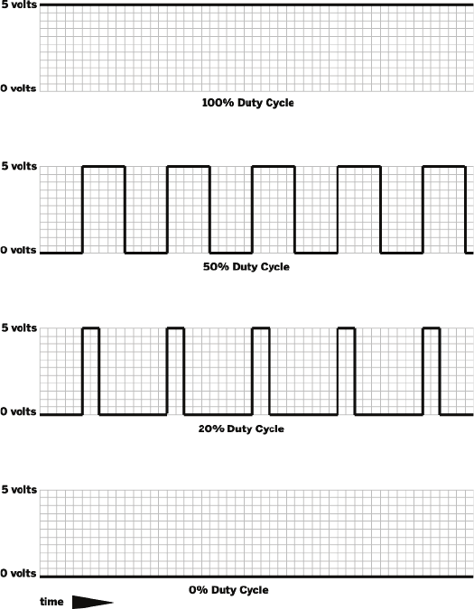
at 20% power, the Raspberry Pi will turn the pin on 20% of the time
and off 80% of the time. The percentage of time that it’s on versus
the total time of the cycle is called the
duty cycle
(Figure 8-2). When
you connect an LED to these pins and instruct the Raspberry Pi
to change the duty cycle, the effect we see is that the LED gets
dimmer.
Figure 8-2.
The duty cycle represents how much time the pin is
turned on over the course of an on-off cycle.
Analog Input and Output 125
GSW_RASPI_4ED_FIN.indd 125GSW_RASPI_4ED_FIN.indd 125 10/28/21 10:54 AM10/28/21 10:54 AM

Test-Driving PWM
For the next few steps, we’ll assume you’re using the desktop
environment, but feel free to use the command line to write and
execute these Python scripts if you prefer:
1. Connect an LED to GPIO pin 25 (physical pin 22) as you did in
“Beginner’s Guide to Breadboarding” on page 94.
2. Open the File Manager by clicking its icon in the taskbar.
3. Be sure you’re in the home directory, the default being
/
home/pi.
If not, click on the home icon under the Places listing.
4. Create a file in your home directory called
blink.py
. Do this by
right-clicking in the home directory window and choosing “New
File.” Name the file
fade.py
.
5. Double-click on
fade.py
to open it in the default text editor.
6. Enter the following code and save the file:
from gpiozero import PWMLED
from time import sleep
led = PWMLED(25)
while True:
for dc in range(0, 100, 1):
led.value = dc/100.0
time.sleep(0.01)
for dc in range(100, 0, -1):
led.value = dc/100.0
time.sleep(0.01)
Create a PWM LED object and set it to GPIO pin 25.
Run the indented code below this line, each time incrementing
the value of dc by 1 from starting at 0 and going to 100.
Set the duty cycle of GPIO pin 25 to the value of dc.
Run the indented code that follows, each time decrementing the
value of dc by 1 from starting at 100 and going to 0.
7. Open the terminal, then use these commands to make sure
the working directory is your home directory, and execute the
126 Getting Started with Raspberry Pi
GSW_RASPI_4ED_FIN.indd 126GSW_RASPI_4ED_FIN.indd 126 10/28/21 10:54 AM10/28/21 10:54 AM

script:
pi@raspberrypi:~/Development $ cd~
pi@raspberrypi:~ $ python3 fade.py
8. Your LED should now be fading up and down!
9. Press Ctrl-C to stop the script and return to the command
line.
If you’re accustomed to using PWM on a microcontrol-
ler like the Arduino, you’ll find that—unlike Arduino—
there is unsteadiness in the PWM pulses from the Rasp-
berry Pi. This is because in this example, you’re using
the CPU to turn the LED on and off. Because that CPU is
used for multiple things at one time, it may not always
keep perfect time. You can always reach for other hard-
ware like Adafruit’s PWM/Servo Driver (www.adafruit.
com/products/815) if you need to have more precise
control.
Taking PWM Further
With the ability to use pulse-width modulation to fade LEDs up and
down, you could also connect an RGB LED and control the color
by individually changing the brightness of its red, green, and blue
elements.
As we mentioned earlier, you can also use pulse-width modulation
to control the speed of a direct current motor that’s connected to
your Raspberry Pi through transistors. The PWM output, when fed
into the transistors, will modulate the amount of power the transis-
tors allow into the motor, and hence its speed.
The position of the shaft on a hobby servo motor (the kind that-
steers RC cars) can also be controlled with specific pulses of elec-
tricity. Though, keep in mind that you may need additional hard-
ware and power to control these motors with a Raspberry Pi.
Analog Input and Output 127
GSW_RASPI_4ED_FIN.indd 127GSW_RASPI_4ED_FIN.indd 127 10/28/21 10:54 AM10/28/21 10:54 AM
..................Content has been hidden....................
You can't read the all page of ebook, please click here login for view all page.