
Small polymeric containers
5.1 Introduction
When large tanks and reservoirs fail, the consequences are usually disastrous because they tend to fail when full, so that the contents flood the vicinity and cause serious damage. Although small containers do not present the same problem, they do present problems of their own when they fail. Battery cases are probably the most dangerous because they usually contain very strongly acidic or basic electrolytes, such as sulphuric acid or caustic soda. If they leak, then serious personal injury can occur to the user, or physical damage to nearby equipment. In addition, the equipment powered by the battery starts to fail, or, when the electrolyte leaks away, fails altogether. So the function of the equipment is lost. Thus a leak from a battery which powers a lamp underground means that the miner loses his light, a potentially very serious incident which could result in an accident. A leak from a car battery can corrode other components and cause an accident. Other failures of battery containers can be caused by an internal spark, which can ignite gas inside the battery, causing an explosion, which can injure anyone unlucky enough to be nearby.
Both thermoplastics and thermosets are almost universally used now for enclosing electrical equipment of all kinds, where their excellent insulating properties are exploited. Thermoplastics have displaced thermosets, especially materials like ‘hard rubber’, which were formerly used widely. But case failure in either material can allow live parts of the inner conductors to be contacted by consumers, with the possibility of electrocution. The integrity of cases is critical to safety, even for such small and apparently innocuous items like plugs on consumer products. The growth in a wide variety of such products imposes constraints on product design as well as the way they are made. More often than not, those products are made in the tiger economies of the East, such as India, China and Indonesia, where quality control and design experience is still growing. There may be a long chain of production, assembly and supply to the consumer, and an early mistake can have far-reaching consequences. Injection moulding can be problematical, with products seemingly correct but yet basically flawed internally. When those mouldings are assembled, small cracks can be created which are almost impossible to detect visually until the final product is stressed by the consumer, when the product fails.
But so many small storage products are made from thermoplastics that failures of such mundane items as plastic buckets can cause serious accidents. Their design needs careful thought not just for the integrity of the device but, recognizing that fracture of key parts is possible, then mitigating the consequences by providing some redundancy in the product. Such ideas are widely used in many safety-critical components on aircraft, for example, where redundancy is a key part of the design process, and the principle should be applied to all safety-critical products.
5.2 Failure of battery containers
As portable sources of energy, batteries have multiplied in their applications ever since their invention and development in the Victorian period. They may be simple primary cells where the case itself is a metal like zinc, which corrodes in a caustic electrolyte to provide the current. The case corrodes from the inside and by the time the corrosion reaches the outside of the can, the cell is exhausted and the product disposed of by the user. Damage from the battery is thus rare but can occur if the corrosion is faster at one point, so allowing leakage faster than expected. Such cells are much more commonly now replaced by improved cells where the chemical mechanism is different. Secondary cells are also common, ranging from very large stand-by batteries available in emergencies, when the public power supply fails, to submarine batteries used for electricity storage, through truck and car batteries to smaller versions for motorcycles. Owing to the low cost of the raw materials, lead-acid batteries are the most common systems used, although many other types, using different reactions and materials, are available for powering electronic devices such as mobile phones and laptops, for example.
5.2.1 Military batteries
Although glass cells were commonly used for many batteries in the early days, the possibility of breakage was so high and the results so severe, that alternative materials such as hard rubber were used. It was originally developed by Charles Goodyear when he discovered the vulcanization of rubber by sulphur in 1842, and is one of the first of many new materials developed in the Victorian period. It is very highly cross-linked natural rubber, with up to about 30% added sulphur plus some fillers such as carbon black or even powdered anthracite coal. The material known as ‘ebonite’ is a superior grade of hard rubber and widely used for musical instrument stems such as flutes and oboes (1). Hard rubber became a common material for use in battery cases since it could be moulded into a variety of fairly complex shapes relatively easily.
However, the material as used in batteries is very brittle and easily damaged by abrasion. That is shown by the problems that can occur in tank battery cases, where large containers are made for heavy duty use in power storage. The design problem with battery cases basically comes down to achieving a compromise between making a container tough enough to withstand handling during manufacture and then placement (and replacement) into engine compartments. Most of the time, the container sits in that compartment without any extra stresses on the external case, but has to withstand those initial handling stresses without damage or cracking. So the material specification can be lowered (so saving costs) but to what extent? If lowered too far, the container may then fail, defeating the primary objective.
5.2.2 Failures
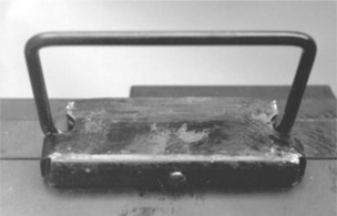
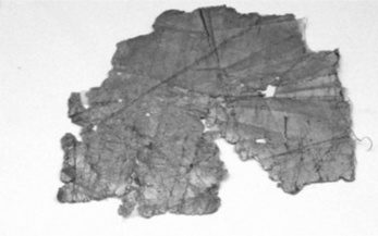
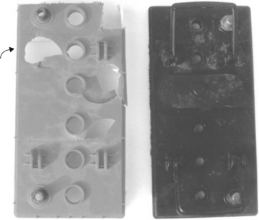
The first failures of a 12-volt tank battery were discovered on the production line, when the steel handles fitted came away from the casing (Fig. 5.1). The handle fitting was held to the case by a single screw on the underside of the case, and the hard rubber had cracked, so releasing the screw (Fig. 5.2). The internal enquiry showed that up to 10 600 batteries in service could have been affected, plus 1409 batteries impounded in the factory. A further 683 items were found to have faulty handles. It was a serious situation, not just for the loss of production, but also for the batteries in service because of the possibility of personal injury to anyone moving them. They requested an independent investigation, which we conducted on several failed cases supplied by the company. Attempts made to repair cracked cases with resin put into the cracks were unsuccessful since adhesion was very poor. Tests at the factory indicated that the failed batteries had been made from poor material, the poor ebonite showing a distinctly lower impact strength 0.24 J/12.7 mm notch compared with 0.39 J/12.7 mm notch.

5.2.3 Investigation
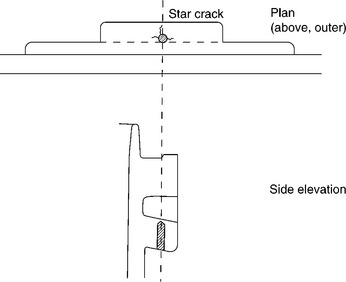
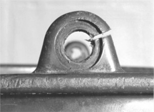
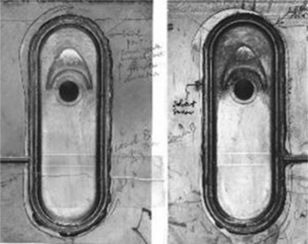
The first task was to examine the cases for the nature of the defects, which were quickly found at the base and sides of the single screw hole drilled into the material after removal of the handle itself. The samples all showed star cracks from the sides of the hole, some penetrating the base of the hole to the free surface (Figs 5.3, 5.4). In other examples, the base had spalled away completely. The material itself was very weak, as confirmed by checks on tensile test bars machined elsewhere from the cases. They were tested to destruction and the fracture toughness (KIc) calculated from the measured strengths (σ):
where Y is a factor related to sample geometry for a single edge notched sample, and c the crack depth. The tests produced a mean result of:
falling to a value of about 0.1 at a much higher test speed of 1000 mm/min. The value is substantially lower than glass, polypropylene or steel (2):

Tests on screw holes and the effect of different diameters were also made, showing that shallow holes produced cracks very readily. Operators had used the correct sized drill bit but had not always drilled them as deep as needed. When the screw is inserted to connect the handle, extra stress will be put on the adjacent material.
5.2.4 Material analysis
But what really surprised us was the very poor composition of the material, whether ‘poor’ or ‘good’. Analysis was difficult because rigid thermosets cannot be examined using FTIR, and generally produce poor DSC thermo-grams. However, a direct approach was used to examine samples, with some interesting results.
Sections of the material were easy to polish to examine the composition, however, which turned out to be (according to the supplier) natural rubber heavily cross-linked with sulphur and filled with powdered anthracite (a type of coal of very high carbon content). The sections showed the anthracite particles shining by their specular reflections in the optical metallurgical microscope. Inspection of the image showed that very high levels of filler had been used, weakening the matrix polymer. Sections showing a brittle crack (cc) next to a thread (t) showed just how brittle the material had become (Fig. 5.4). The particles were highly angular with sharp edges and points, and showed a very wide distribution of sizes, none of which had strengthened the material. Other sections showed up flow lines and probable weld lines within the bulk, yet another weakening effect in what was a seriously weak material for the job of supporting 30 kg weight of the contents. The volume fraction of anthracite estimated from the sections indicated a loading of about 75%. Carbon black itself is a very good reinforcing agent when used in car tyres at much lower loadings, but the particles are much smaller and much better distributed to achieve the desired increase in strength and modulus.

5.2.5 Conclusions
The investigation concluded that failure had been exacerbated by poor drilling during manufacture, but the material itself was mainly to blame. Why and how such a grade came to be used in the first place remained a mystery. The drawings were so old as to be partly illegible as to when it had been introduced, and the company itself could not tell us either. The supplier blamed the failures on lower quality anthracite ‘… on account of the recent miners strike …’ but that could only have been a partial explanation. Variations were also found in the shape of the metal handle which could increase the stress on the screw and hence encourage cracking. The thickness of the steel plate used had recently been reduced from 1.84 mm to 1.71, reducing its stiffness, and so making distortion under load easier. In other words, more of the load was transferred to the case and made failure more likely.
To put it bluntly, this was a seriously flawed design: to use just a single screw to hold such a heavy product in what was a very weak and brittle material defied belief. The casing needed very thick walls (½ inch/12 mm) to resist drops and minimize any stress concentrators such as corners. But screw holes themselves will magnify the stress by at least three, so extra special care is needed when adding essential devices like handles. While the immediate cause of the failures might have been under-drilled screw holes and thin steel handles, the long-term problem of using very poor materials would have to be addressed before serious claims might be made against the company. Far better materials were available and it is understood that this battery and others have since been redesigned using polypropylene.
5.2.6 Aircraft batteries
It also later turned out that the same company were having related problems with 12 V aircraft batteries, and the root cause was the same. Problems appeared in 1985 on the now defunct aircraft, the Canberra. Leaks of sulphuric acid electrolyte had occurred from the vent holes, so endangering the aluminium airframe. The RAF had quarantined a large number of similar batteries owing to the risk of leakage.
Each of six vent holes in the top of the case was fitted with a transparent plastic non-leak valve, which screwed into the hard rubber casing of the battery. Inspection of the threads in the cases showed severe damage such as cross-threading, degrading the capability of the joint to seal the contents (Fig. 5.5). The threads were made during moulding by using a retractable core which is unwound from the solid product at the end of the moulding cycle to allow the product to be withdrawn from the tool. The operator then deflashes any excess material extruded through gaps in the tool mating surfaces.

The independent investigation concluded that although deflashing could help initiate loss of thread, the cause of failure lay in the material being incapable of resisting abrasion from the plastic thread of the valve. It was clear that such designs should be scrapped, and hard rubber replaced by a much tougher and reliable material like polypropylene. Once again, the root problem was the poor material of construction.
5.2.7 Patent action
In fact several large battery companies in the UK had already started a programme of introducing polypropylene into car battery cases, by far the largest product of the lead-acid battery market. That fact emerged in a patent battle which came to trial in the Patents Courts in 1977 (3). Thin wall containers were patented in the USA (extended to the UK) by Polycase (Fig. 5.6) and it was clear that the material had many advantages over hard rubber for battery casings. The walls were only 2–3 mm thick, so saving a substantial amount of polymer compared with the 6–8 mm of hard rubber cases. The material was much tougher so that the cases could withstand rougher treatment when handled. In addition, details such as threads and ribs could be designed into the product with greater confidence so that they would be safe during use. Numerous ribs were needed to stiffen the casings owing to the rather low tensile modulus of the polymer. The lids could be welded thermally with ease owing to the sharp melting point of about 165 °C of the material.

A number of UK manufacturers developed very similar cases in PP, some of which were also patented, but the Polycase patent won the infringement action since it had established priority. All cases that used the same principle had to pay royalties to the patent owner. It was clear that the use of the thermoplastic would replace hard rubber as the standard casing material, although other thermoplastics came to be used as their often superior properties came to be recognized.
The replacement of hard rubber did not come easily. The companies had to invest large sums of money in the complex tools needed to make the cases, which were then manufactured using external trade moulders. The assembly lines also had to be modified to suit the new materials. The independents certainly had the expensive injection machines to supply the products on a fixed-price contract. Experience in using some of the new polymers, however, was in short supply and would create unforeseen problems.
5.3 Failure of buckets
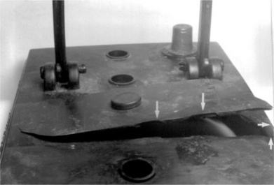
Some tough materials like LDPE came into question when they also failed to resist imposed loads. The common domestic bucket moulded in thermoplastic materials was a big improvement over the traditional galvanized steel bucket, being much lighter, and thus easier to use. It was fitted with a steel wire handle. However, an employee was using such a bucket when it suddenly failed at one of the projecting lugs (Fig. 5.7), and she was scalded by the spill of hot water she was carrying in the device at the time (Fig. 5.8). Since she was working at a factory, she could be compensated for her injuries if the insurers were convinced that it was not her fault that caused the accident. They approached us for an independent assessment of the incident. The lug had broken in a brittle fashion across its diameter, the fracture starting at one of the inner corners (Fig. 5.9). The exposed surfaces showed wear from abrasion, and both lugs showed creep so that the handle holes had become elongated. So what had caused such a sudden and instantaneous failure in a tough material?


A full bucket of water imposed a load of 45 Newtons on each of the two lugs. The round lugs of a steel bucket have a cross-section of about 15 mm2, giving a stress of about 3 MNm− 2 in each lug. Since the tensile modulus of steel is 210 GNm− 2, the elastic strain is very small at about 1.4 × 10− 5. With a much smaller modulus of only about 0.2 MNm− 2, LDPE would show substantial deformation for the same load (2). The lugs had to be thickened to limit the strain to a more acceptable figure. In the event, the designer chose to increase the section area to about 57 mm2, so reducing the stress to about 0.8 MNm− 2, with a strain under load of about 0.4%, well within the tensile strength of the polymer of about 10 MNm− 2. This was considered a reasonable and acceptable degree of deformation at the time. However, the real stress on the lug would be greater owing to the stress concentration of the hole itself, which was estimated at about six times the nominal stress, so giving a stress of about 4 MNm− 2 on the device (still well within the material strength). There was a sharp corner in the design (Fig. 5.8) which may have increased the stress further, but the crack did not start here but on the opposite side of the lug. There had to be another explanation for the failure.
There was no obvious evidence of fatigue, such as striations concentric to the origin where the crack had grown intermittently, and there was no evidence from the bucket itself of abuse or mishandling by the worker. For example, there were no abrasions or cuts at or near the lug which could have caused the fracture. Tensile test bars cut from the sides of the material proved it to be of normal strength, and it had not been affected by UV degradation either, as FTIR spectra showed. Although brittle cracks could be induced by exposing the material to carbon tetrachloride, as far as was known the bucket had not been in contact with either this or any other organic fluid.
5.3.1 Weld line formation
The final possibility considered was perhaps a problem with the injection moulding process used to make the product in a single operation. The object had been made from a single gate in the base of the bucket, so that molten plastic entered the tool here, and progressed steadily up the sides to the top and the lug recesses. A problem frequently arises where the molten polymer front has to move around an obstacle in its path, thus splitting the melt into two separate streams. When the melts rejoin at the other side of the obstacle, a weld line can often be formed if the polymer has cooled too much in its travel. It is effectively an area within the solid where material has failed to unite to form a coherent bond. Weld lines are not unusual if the tool is unheated, because the polymer melt will cool as it touches the steel tool surfaces, especially at the end of its run. Several weld lines were indeed found in the region of the lug on the outer surfaces, confirming that one such weld line was the cause of the failure. Needless to say, the culprit weld line was destroyed by the fracture. Although one might have expected a weld line to have formed at the apex of the lug, it is not unusual for them to occur at other points than expected. If, for any reason, one of the melt fronts travels slightly more slowly than the other, then they will meet asymmetrically, as in fact happened here. The weld line represented a permanent defect which could have failed at any time the bucket was loaded to the brim. It was effectively a nascent crack waiting to be parted.
The worker concerned was compensated for her injuries, and the well-known company who had made and sold the item contacted us for further help on the design. Upstanding parts will always be susceptible to weld lines, however hard the moulder tries to eliminate them, so an alternative solution was needed. Fortunately other manufacturers had faced the same problem and had found the solution: lugs set below the upper rim, and so reinforced by the wall as well as an outer part. In the event that the lug failed, the end of the handle would still be held by the recess, giving the product failsafe performance. Such designs are now universally adopted, and provide the user with much greater protection against sudden and unexpected failure (Fig. 5.10). By eliminating all possible failure modes, the investigation arrived at the only feasible mechanism by which the product failed, despite the lack of direct proof. But then most failure analysis usually relies on circumstantial evidence and experience of previous failures.

5.4 Exploding batteries
An unexpected problem occurs with lead-acid batteries when they suddenly explode. It can occur when one of several failure mechanisms occurs independently of the quality of the plastic case itself. In the era before so-called ‘maintenance-free’ batteries, users needed to top up each cell of their car batteries with distilled water. It was needed because water is lost by evaporation and, more likely, by electrolysis. The latter is an undesired by-process of the function of a lead-acid battery, which normally stores electricity on charging by converting lead sulphate (PbSO4) to the high energy compound lead dioxide (PbO2) in the presence of sulphuric acid. The concentration rises to 40% in a fully charged battery, a highly aggressive liquid. However, the much simpler reaction also occurs on the free metal surfaces dipped into the acid, especially when all the available lead sulphate has been converted to the lead oxide:
So liquid water is converted into two gases in exactly the right composition to recombine to form water again by the reverse reaction:
However, the reaction is usually slow, and pressure builds up above the electrolyte unless vented to the atmosphere (often through leaky screwed stoppers). On older batteries the gas mixture could explode when ignited by the electric sparks ever present in car engine compartments, although the damage was usually not serious since the air space is large. On the other hand, a serious fire could occur if petrol fumes were ignited. On maintenance-free batteries, the cells are designed so that the two gases recombine smoothly, usually at a higher pressure than atmospheric. They are fitted with valves that can open at higher inner pressures (at about 6 psi, for example) if recombination is inhibited.
Unfortunately, valves can be blocked by the grease and dirt in engine compartments, so that pressures can build up to unacceptable levels. This in itself could cause the case to burst, but a more likely result is an internal short circuit which causes the mixture of gases to explode, as the following examples illustrate.
5.4.1 Fire brigade incident
In July 1987, a stand-by 100 amp hour 12 V battery exploded at a station of the Humberside Fire Brigade. It was one of a set of about 100 used by the brigade and was under regular and constant charge, ready for use at any time. The battery had been delivered new in December 1986, so the failure could not be attributed to damage from old parts, for example. The battery was dissected so that the damaged parts could be examined in detail. The top exhibited cracking of cell 4, and cell 3 was dead (Fig. 5.11), but careful inspection showed that there was some sooting on the underside of cell 2. All the valves were intact although that from cell 2 showed signs of burning, so accounted for the soot remains found on the underside of the lid. The valve was made form polystyrene, a highly flammable polymer. Each individual cell was then tested and all proved in a state of charge apart from cell 3, which was dead. The casing was cut open and the plates from each cell examined one by one. The plates from cell 4 showed showed a ‘sulphation ghost’ on one of the positive plates indicating a possible short circuit. The plates were badly corroded. The plates from cell 3 were also badly corroded, and there had been dendritic growth between the plates through the microfine glassfibre separators. Such growth is unusual in such a young battery and had shorted the plates so that the whole cell was dead. The mechanical strength of the lead connectors within each cell were also tested and proved satisfactory, with no fractures. Cell 2, however, showed signs of shorting at the top corner of one of the grids, and the other intact cells also showed signs of positive plate corrosion.

The lid fractures showed that no less than five simultaneous brittle cracks had been formed on the outer lid surface, which had grown to completion to form the final flap (Figs 5.12 and 5.13). There could be no doubt from the outward inclination of the flap and the large number of origins that failure had occurred from an internal explosion. The valves were checked and all proved to be in working order, releasing gas pressure when it had risen to 6 psi above atmospheric.

5.4.2 Material quality
The tensile behaviour of the wall material was also examined by cutting tensile dumbbell bars from sheet taken from the battery and testing at two strain rates. The tests of the polypropylene proved that the material was strong and ductile, although the strength dropped with increasing strain rate, a perfectly normal response. The breaking strength was about 32 MNm− 2 at a strain rate of 100 cm/min crosshead speed, the material showing a clear yield point, then cold drawing before fracture.
The densities were also normal, at about 0.94 g/cc. FTIR spectroscopy showed no carbonyl groups present, so the material had not been oxidized. The method gave an ethylene content of 3% by weight, so the material was actually an ethylene-propylene copolymer.
5.4.3 Hydrogen explosions
There is an extensive literature on hydrogen explosions, both as a subject of scientific study and the damage they can cause. The subject had been investigated in the Victorian era first by Berthelot and co-workers and discussed in Bone and Townend (4), who used small bombs fitted with a piston (Fig. 5.14), the smallest being not dissimilar in volume (300 cc) to that above each cell (about 340 cc, depending on the electrolyte level). They measured the pressure developed in various gas mixtures, the greatest pressure of 7.6 atmos being developed for a stoichiometric mixture of hydrogen and oxygen. The flammability limits of hydrogen in air are very wide, from 4% to 75%, and the detonation limits narrower, from 18.3% to 59% at atmospheric pressure. The limits are proportionately wider for a pure oxygen atmosphere. The ignition temperature in air is very low, at 585 °C, and the flame can reach a temperature of just over 2000 °C.

The damage evidence suggested that the gas mixture in cell 2 had burnt rather than exploded, judging by the soot marks on the underside of the lid, so the combustion mixture fell outside the detonation limits. However, it was possible to determine the hydrogen concentration knowing that the oxygen index of polystyrene is 18.5% (5). This means that it will only burn freely in air with more than 18.5% oxygen. It works out at about 12%. There would have been some arcing in this cell to ignite the gas mixture, but arcing must have been less in cell 4, allowing the pressure to rise before a detonating explosion blew the lid out.
So the explosion had been caused by a failure of the cells, which occurred rapidly in the few months since it had been installed. One cell went dead and the remaining cells were then overcharged. Sparking within the two cells next to the dead cell led first to a fire in the one, and then an explosion in the other. But more serious explosions can occur in older cells where the gas-release valves fail and allow higher pressures of gas to accumulate.
5.4.4 Personal injury
Reporting on industrial incidents is often much easier than accidents where litigation is contemplated because of the loss of evidence and time lapse between an incident and its investigation. It makes the job more difficult but more challenging. We were approached in 2004 to investigate an accident where a garage mechanic had lost an eye when a 12 V car battery exploded. He said that he was renovating a vintage car and went to remove the battery, which was situated in an awkward position under one of the seats in the car interior. The battery seemed to be flat, so it would need recharging, and needed to be removed for that to take place. As he came to move the battery, it suddenly exploded. Since he was close to it when it disintegrated, he was severely injured by fragments of plastic from the top as well as an acid spray raised by the explosion (Fig. 5.15). He wanted compensation for his injuries, having lost his job at the garage and without good prospects.

The top of the battery in a picture he took shortly after the accident showed extensive fracturing of the top, with four of the six cells exposed to view. Electrolyte levels were high, showing that the battery was not old. There appeared to be no distortion of the plates. Unfortunately, none of the pressure-relief valves were collected after the accident, so could not be pressure tested.
When examined, the battery ends showed extensive deformation (Fig. 5.16), despite the fact that the accident had happened a year before in 2004, and the battery had been stored as it was, after the incident. Plastics creep under load, and it was clear that the permanent deformation or bulging of the ends could only have been produced by long-term high internal pressure. One end had also cracked at the centre of the panel, suggesting that the final event in over-pressurization was a violent internal explosion, as might be expected with the top showing extensive fragmentation (Fig. 5.15). When examined, the plates had sulphated and become distorted, but were originally in a good condition after the accident.

A photograph taken at the time of the accident showed the distortion in the casing was present then, so the bulges in the ends could not have been produced by plate expansion, for example. The lead metalwork inside the battery appeared intact and undamaged.
The brittle cracking of the case was very similar to that found in the previous investigation, showing that the polypropylene could not withstand the high pressure generated in hydrogen explosions. But what caused it to explode? There were several possible theories. In the first place, the bulging of the ends suggests that over-charging had occurred, perhaps after one cell had failed. It is also likely that the pressure relief valves had failed to release the pressure, allowing a dangerous mixture of hydrogen and oxygen to accumulate above the electrolyte. When the battery was jarred by the mechanic trying to move it, a spark inside the battery ignited the gases, which exploded with great violence and shattered the case. It is interesting to note that the damage to the top was considerably greater than that in the last example studied, where only one cell had been broken. That implies that the internal pressure was much greater, so increasing the power of the explosion. One cell igniting would have triggered similar explosions in the other cells.
Battery explosions are more common than might be supposed, several examples being described by their users on the web (6), and more serious incidents have occurred in battery charging rooms, where much greater volumes of hydrogen can accumulate (7). The subject is of great topical interest owing to the possible use of hydrogen as a fuel for cars powered by fuel cells, which generate electricity by allowing the gas to react with oxygen on a catalyst substrate. The technology is well developed and organizations like NASA have long experience in dealing with liquid hydrogen fuel for rockets (8).
5.4.5 Hindenburg disaster, 1937
However, hydrogen in the past has caused some disasters, most notably the fire that engulfed the Hindenburg airship in 1937 (Fig. 5.17). The precise cause is still a matter of debate, but the facts are undisputed (9). On the night of 3 May 1937, the Hindenburg left Frankfurt for Lakehurst, New Jersey. It was the pride of Germany, the country having pioneered the use of giant airships supported by hydrogen held in cells within a rigid aluminium alloy frame. The idea had been developed by Zeppelin before the First World War (when they were used to bomb Britain). They had been the most successful in exploiting the commercial possibilities by developing commercial services, and had been supported by the Nazi government. Hydrogen gas was used as the main lifting medium because the safer helium gas had been embargoed by the US government. When it arrived at Lakehurst on the evening of 6 May, the weather was threatening and thunderclouds had only just cleared the area. As it came into land, it dropped water ballast to trim its attitude because the rear end was falling compared to the rest of the fuselage. A mooring rope was dropped to the ground just afterwards, when the ship was 90 metres from the ground and 244 metres from the mooring mast. A small fire was then spotted at 7.25 pm by witnesses on the ground, and the fire spread rapidly from near the rear fin as the fire took hold (Fig. 5.17). The sequence of events was recorded live on air by the reporter Herb Morrison as the craft descended to the ground in flames. Of the 36 passengers and 61 crew, 13 passengers and 22 crew died. In addition a member of the ground crew was killed. Most deaths were not caused directly by the fire but by jumping from the burning airship. Those passengers who rode the airship on its descent to the ground survived.

The subsequent enquiry (10) investigated several possible theories, including sabotage. They concluded that a static electricity spark (from the thunderstorm) had ignited a leak of hydrogen, probably when the mooring rope was dropped and earthed the structure. However, the disaster remains an active area of investigation owing to the uncertainty in the evidence. Recent work by Addison Bain (11) has shown that the fabric was a highly inflammable mixture of cotton fibre, cellulose dope, iron oxide and aluminium powder (Fig. 5.18). The composition is similar to that of a thermite mixture (widely used for incendiary bombs in the Second World War) and Bain suggests that the fire started with sparking of the fabric, and then spread to the stored hydrogen. Whatever the exact cause, the disaster ended the reign of the airship and the remaining ships were scrapped; the aluminium was recycled into military aircraft of the Luftwaffe. Britain’s own airship programme had been halted in 1930 after the R101 disaster, when the heavily laden airship crashed at Beauvais on its way to India and caught fire, killing 48 passengers and crew. The tragedy was blamed on poor quality outer fabric which tore open during the storm the ship was negotiating at the time. However, the advent of new high-strength polymer fibres like aramids and modern elastomers has rejuvenated the industry, at least for small airships. They use helium rather than the much more hazardous hydrogen for lifting purposes.
Industrial accidents also occur, such as that at Laporte Chemicals in 1975, when an electrolytic cell used for hydrogen production exploded. One man died from severe burns when the caustic soda electrolyte was expelled (12). The accident was caused by corrosion within the cell, of which some warning had been given just prior to the incident, but went unheeded. The explosion caused severe damage to the building housing the process. The investigation showed that oxygen and hydrogen was caused by unexpected corrosion within the cell, and the gas mixture ignited by an internal short, not unlike the battery explosions already discussed above.
5.5 Failed truck battery cases
With the widespread adoption of polypropylene for car battery casings prompted by the Polycase patent (Fig. 5.16), the next target was to be truck and traction batteries. They are usually heavy duty, needing more stored energy for the greater demands of lorries and trucks when compared with car usage. Traction cases are usually larger again, being used on locomotives, for example. Because they inevitably contain more lead in the form of plates and grids, they are much heavier, so putting extra demands on the case. It implies that detail design and choice of the best grade of polymer must be to higher standards than accepted for car batteries. We were involved in the design stage when the company asked for evaluation of the strength of the cases first moulded.
5.5.1 First failures
The first design was rather fragile, as several returns from users showed (Fig. 5.19). The particular complaint came from Ford, who returned smashed cases for evaluation. Like other major users, they had specifications for proving batteries, most important of which was a pendulum impact test involving a 1 kg sphere moving through 1 metre to hit the case. Since the energy, E is simply:
where m is the mass of the striker, g the acceleration due to gravity (9.81 ms− 2), and h the height through which it moves, the test has an energy of 10 joules, a rather modest value. Various parts of the product can be tested since the ball is small compared with the size of the container, and each part must exceed 10 joules. However, the cases were failing in many different places, so we were asked to examine the design and report back.
The examination took several forms: the grade of polypropylene used, the way it had been moulded and the geometry of the design. A check using FTIR spectroscopy showed the material had not degraded or oxidized, and that regrind polymer had not been used. However, GPC analysis showed that the grade of polymer was the lowest strength material supplied by ICI. It also had the highest MFI (melt flow index), a rough guide of its molecular weight. The moulding process appeared correct, but the design included numerous sharp inner corners which acted to weaken the product drastically (Fig. 5.20). Although the specification drawing gave recommended radii, the product had much higher radii when examined directly. Thus the lower inner corners had a radius of 0.5 mm compared with the specification of between 1 and 1.6 mm. It was clear that the toolmaker had not conformed to the drawing in these key design details, and so unintentionally weakened the product. At buttresses, the corners were 0.05 mm compared with a recommendation of 1 mm. In addition, the extruded bead of molten polymer at the thermally welded lid of the case had radii of about 0.02 mm, and extremely sharp corners which initiated brittle cracks when impacted. While such radii are beyond easy control, the other stress concentrators could be easily rectified by simply rounding out the sharp external corners of the steel tool core.

Figure 5.20 Sharp inner corners on truck cases: actual radii in mm with specification in parentheses.
It was clear that the lowest grade of polymer had been used to make the cases, and should be changed immediately to an improved grade. The higher impact grades of polypropylene are copolymers with ethylene, and also have lower melt flow indices (higher molecular weight). The two changes (increased radii and higher grade) resulted in an acceptable product which passed approval tests. However, it seemed that trade moulders always used the lowest grades of polymer in the absence of specific instructions, probably because it made moulding much easier and gave higher production volumes since the cycle time is generally lower. Such behaviour guarantees product failure, and is costly to track down and change because by the time the mistakes are discovered by testing, a large number of products have been made, and must be scrapped. In the worst case scenario, where testing is absent or ineffective, such defective products enter the market place and cause accidents. Toolmakers should have no excuse for leaving sharp radii in products, but many seem quite unaware of the damage they can create by not meeting a clear specification on the drawing with which they are supplied. The presence of sharp corners is of course not limited to heavy batteries, but has been used in many other products, where they continue to provide a convenient route to premature failure, often at the user’s expense. This may be one reason why many plastic products have such a poor reputation with consumers. Designers really should know better, although few have any detailed knowledge of the mechanical behaviour of the materials which they specify.
A final point was made in the report. The carrying handles were a particular hazard given the problem of a similar design in the failed bucket. The stress concentration factor in the battery was estimated to be about 5.2, which together with the distinct chance of a weld line, made it an unacceptable feature. It was recommended to be removed and alternative means of carrying the case adopted. Carrying handles are now usually pivoted under the rim, while car batteries generally either have lips on the main case or a strap to aid lifting. However, some designs still retain an exposed lug on the lid, and should be treated with respect when lifting.
The much larger traction batteries and standby batteries for computer protection (in the case of a power cut) are installed only once with specialist handling equipment. But even here, there can be problems as is described in the case of a fire on the Hong Kong transit system in the next chapter.
5.6 Failures in miner lamp battery casings
Coal mining underground has long been a hazardous occupation owing to the ever-present flammable gas methane, with explosive limits 5.3–17%, and detonation limits 6.3–13.5% at normal atmospheric pressure, much narrower than hydrogen. Nevertheless, methane explosions have caused some of the worst pit disasters in the long history of coal mining, and still continue today in countries such as China and India with their rapidly developing energy base. The first important safety lamps were invented independently by Davy and Stephenson in 1815, and were based on the need to restrict access of the outer atmosphere to the burning flame of the lamp. Davy used an iron gauze, while George Stephenson used a system of narrow pipes. Neither lamp was a good source of light, and actually gave a false sense of safety, since they were easily damaged and rendered unsafe. It only needed a single break in the gauze to allow explosions, a situation easily caused by rusting of the gauze, and deaths from methane explosions continued to rise. The worst mining disasters were yet to come, because methane explosions raised coal dust from the galleries, and it exploded in turn. Such dust explosions were much more serious because they could engulf the entire pit. Michael Faraday and Charles Lyell investigated just such a devastating explosion at Haswell colliery, Co. Durham in September, 1844 which killed 95 miners, and concluded that coal dust was to blame. Such disasters culminated in the disaster at Senghenydd colliery on 14 October 1913, killing 439 miners (13).
Many attempts were made to improve the design of the safety lamp, including use of a glass screen around the flame and multiple rather than a single gauze, but the light was always very poor when cutting a black mineral in the dark. Matters improved when electric lights (14) came into use as late as 1911, powered by a portable battery (iron-nickel or lead-acid). At first they were carried by hand, but a head lamp was invented in the 1920s for attachment to a hard hat, and so allowing the miner free use of his hands. The safety of the lamp relied initially on metal cases, but non-metals such as hard rubber soon came into use.
But the introduction of polypropylene for car and truck batteries prompted manufacturers in the USA to design a new kind of case, in thermoplastic polycarbonate. The material was tough (at least in extruded sheet) and was advertised for bullet-proof glazing. The material was stiff enough to be used in 2–3 mm thick walls, and details such as belt loops and ribs could be designed into the case and made in one step by injection moulding.
The existing design used in British collieries consisted of hard rubber with a central screw vent for topping up the electrolyte in the single cell. There had been problems with leaks from this vent – not unsurprising given the problem of leaks from larger battery cases. The miners’ lamp battery was different in design from traction truck or car batteries: they are designed for providing an initial deep discharge of power when cranking the engine during start-up, but thereafter, they are fully charged and provide a smaller amount of power for lights, heating and sparking (if a petrol engine) but are constantly recharged by the generator. They should always be at a state of near complete charge. By contrast, miners’ lamps are deep discharged during each 8-hour shift, and must be recharged on a frame in the lamp room of the colliery when they are not being used. They require much more robust separators (often a glass fibre mat) between the positive and negative plates to prevent dendritic growth of material between the plates, which if it succeeds, short circuits the cell and loss of power results.
5.6.1 New design in polycarbonate
However, polycarbonate is not easy to injection mould because the molten polymer has a high viscosity compared with conventional polymers, and is also non-Newtonian in behaviour (Fig. 3.3). This means that the viscosity does not fall very fast as the shear rate increases in the narrow pipes of the moulding machine and tool, so it can present difficulties, especially to trade moulders who were experienced in conventional polymers like PMMA, polystyrene and ABS. The lower molecular weight grades needed for injection moulding possessed lower strength than the higher grades used in extrusion, so there might be problems in designing polycarbonate products. There are other problems, too, especially in terms of the problem of unwanted chain orientation, a problem of frozen-in strain. If the tools are held at ambient temperatures, or even cooled (as is common with many other polymers), then the material is quenched so that the polymer chains are locked into non-equilibrium shapes. If the temperature is raised, the product can distort, and the strength also falls in areas of high chain orientation. Cracks may be initiated during manufacture from those areas in the moulding.
Following the introduction of polycarbonate battery cases in the USA in the 1960s, other companies worldwide tried to imitate the product. Unfortunately, designs were introduced without sufficient testing or evaluation under the severe conditions used in collieries, resulting in large numbers of failures. The design was different from the US case, probably to avoid any intellectual property problems (such as design copyright for example). But the changes in design were to produce problems of many other kinds, and quite unexpected to the engineers concerned.
5.6.2 First failures
We were approached by a large Manchester battery company, Oldhams of Denton, in the mid-1970s when failures were reported from several collieries across the north of England, especially in Lancashire and Yorkshire. The National Coal Board (NCB) asked for an independent investigation of the problem, which was clearly affecting working conditions in the pits. Indeed, the National Union of Mineworkers had threatened legal action over damage to clothing from the acid spillages from brittle cracks in the cases.
The failures had been occurring since July 1974 when the first new design in polycarbonate had been introduced. With a total of nearly 60 000 new lamps sent to pits over the two-year period to 1974, the failure rate varied from 1.7 to 6.8%, and the average over the whole period was 3.3%. The majority of returns from the lamp rooms (where most failures were found) were battery cases which leaked acid (60%) followed by damaged cases (25%), the rest comprising broken belt loops (7%), lid-case leaks (0.7%) and other unspecified fractures. Although the overall figure of 3.3% might seem small, there were 1964 returned batteries to be examined, and in fact it was a very serious situation because it indicated that the basic design could be faulty. To impress on management the urgent need for attention, two graphs of failures were presented (Fig. 5.21), one being a normal linear histogram, the other one plotted on a logarithmic base to emphasize the failure rates.

The main symptom of failure was leakage of sulphuric acid from the windows fitted to the front of the 4 V cases, devices intended to allow the electrolyte to be topped up by lamp room attendants, where the lamps were stored when not being used (Figs 5.22, 5.23). The brittle cracks occurred around the edges of the windows, and grew with time following manufacture. Failures were occurring in new lamps and so it was necessary to inspect the way they were made at the factory.


5.6.3 Solvent cracking
The critical step in assembly was the joining of the various parts together. It was done by solvent welding using a powerful organic solvent (a mixture of methylene chloride and ethylene chloride, CH2Cl2 and C2H4Cl2). Such solvents are normally used for dry cleaning clothes, where they are very effective. The solvent penetrated and softened the polymer before the two parts were pressed together, and the joint allowed to dry. It included the two windows and the top to the main moulding. Using such a volatile liquid gave an immediate problem in the welds, because bubbles formed very quickly as the solvent evaporated. However, such defects could not explain why brittle cracks occurred away from the weld itself. Another mechanism was operating. But one recommendation was to use a solution of polymer in the volatile mixture so as to produce a more viscous adhesive, and less prone to splashing or volatilization. We also recommended using smaller volumes of adhesive, and testing every lamp by applying a pressure test to each window to check that good seal had been formed. A later test using a torque wrench on every battery loop was introduced to ensure strong belt loops.
The cracks were ESC (environmental stress cracks) where solvent interacted with the polymer and the cracks grew slowly. It is well known that swollen polymer is much weaker mechanically than the solid, but an applied stress is needed to encourage crack growth. Although the problem of residual stress is found (such as in storage tank liners), there is another effect in polymers known as ‘residual strain’ where unwanted chain orientation from moulding can relax, and so form cracks when exposed to certain organic liquids. The orientation can be detected using polarized light, so it was necessary to have transparent sample boxes made to check moulding conditions. At the same time, the moulders should supply data on their moulding conditions to check that they were complying with manufacturer’s recommendations.
5.6.4 Strain birefringence
The transparent cases were examined by simply placing them between crossed polars using Polaroid sheet, the same sheet plastic used in sunglasses. Any chain orientation shows up as coloured fringes when seen in white light, or black and white fringes when viewed in monochromatic light. The effects of welding could then be compared directly. The photographs showed that there were high levels of orientation near the window, and that it was modified by solvent welding (Fig. 5.24). The relation between birefringence Δn and the principal stress difference Δσ is simple:
where Q is the strain optical coefficient, which for polycarbonate is 80 × 10− 12m2N− 1. The sequence of colours produced is of a series of red fringes of decreasing intensity as the birefringence increases. The first order red is equivalent to a stress of 2.6 MNm− 2, the second order red to 4 MNm− 2 and so on. In the colour pictures a first order red can be seen close to the edge of the window, while higher order reds lie further away. The red fringes are represented by dark lines in the black and white figures. Solvent welding changes the pattern, but the first order red fringe remains. So a strain existed in the edge next to the solvent weld, and solvent-induced cracks grew from the moment the batteries were assembled.
Photographs of the front of the case showed the problem of orientation in the face of the box, with high-order fringes located at abrupt changes in the melt flow (Fig. 5.25). The injection points at the gates are visible at the bottom of the picture, while high-order fringes can be seen next to the edges of the box where the flow has been forced around the corners of the product. The walls also show high orientation near corners and edges near the top of the case (Fig. 5.26). Such zones were studied later when other defects in the design became apparent.


The method is quite general to many other transparent polymers, including polystyrene, HIPS and SAN as well as polyurethanes, all of which have high stress optical coefficients. Simply placing a sample between crossed polars reveals not just the flow patterns made by the polymer during moulding, but also such features as weld lines and the point of injection. High chain orientation occurs at corners, where the molten polymer is forced around the obstacle (the corner of the tool). This is one reason why sharp corners are especially pernicious in product design owing to the high stress concentration combined with high orientation: a deadly mixture.
5.6.5 Property checks
It was prudent, however, to check that the polymer had not been degraded during manufacture, a problem which can arise if the polymer has not been dried correctly. Polycarbonate like many other step-growth polymers is susceptible to hydrolysis at high temperatures if even traces of moisture are present. So samples before and after moulding were checked using GPC, a method which gives an idea of the molecular weight distribution of the polymer. If hydrolysis had occurred, then the distribution would be expected to fall. However, the samples all showed identical or very similar distributions.
The mechanical properties of tensile dumbbell-bars machined from cases were checked, and found to correspond in showing a yield point before failing after yield, and the start of cold drawing (Fig. 5.27). However, the red filled polymer showed lower tensile strength compared with transparent samples. Used red boxes showed yet lower strength, a reflection of the surface damage and abrasion, and an indicator of the notch sensitivity of the polymer. The lower strength of red filled polymer is a symptom of the effect of fillers on properties: very few increase the strength and most in fact lower the strength by providing particulate stress concentrations within the material. A major recommendation of the initial report would therefore be to switch grades to a transparent polymer. The suggestion was adopted, although a black dye was added to obscure the battery innards.

The fracture surfaces of the window cracks showed completely brittle characteristics, and details showed how the cracks had started and grown. The macrograph of the top of the cracked window showed the presence of numerous holes in the weld caused by premature evaporation of solvent (centre) and cracks appear to have started here and grown intermittently through the sides of the window. Closer inspection of the crack surface showed as series of lines roughly at right angles to the crack growth direction, suggestive of a fatigue process, perhaps induced when the batteries were used by miners. Information from the NCB (and our own experience) suggested that miners used the battery hung from the back belt, as a wedge when passing through narrow workings. Such use would put extra stresses on the window area of the case. Further research revealed an innovative new way of examining the properties of the material.
5.6.6 Polishing
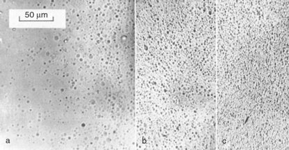
The effect of surface quality on strength led us to develop methods for polishing the surface, and it turned out that this polymer could be polished by chemical milling, a method long used by metallurgists in examining thin foils for electron microscopy, for example. After screening many chemicals, a solution of potassium hydroxide (KOH) in methanol (MeOH) was found to produce the fastest rate of attack (15). The effect on the strength of polycarbonate was rather dramatic, with the cold drawing region extended well beyond the zone just after the yield point where it usually fractured (Fig. 5.27). The method also produced numerous etch pits when examined under the optical microscope (Fig. 5.28), the shape and distribution depending on the mechanical history of the part examined. Thus polymer strained near the yield point (a) showed circular etch pits, while beyond yield the number increased markedly (b). At fracture the shape of the etch pits changed so that they became elongated at right angles to the strain axis (c). There could be little doubt that they represented craze formation within the bulk material. The method of etching polycarbonate is actually widely used for counting damage from radioactive materials in the badges used by personnel working with such hazardous materials (16).
The new phenomenon was investigated by following the change of profile of scratches of known width and depth inscribed on the surface of PC samples using a diamond point mounted in a rig (and known affectionately as ‘little scratcher’). The method had been used by others to measure the thermal relaxation of grooves in silicon-iron (17). The rate of polishing could be followed using double-beam interference microscopy with yellow sodium light, a convenient monochromatic light source (Fig. 5.29). The composite picture shows two sets on interferograms, the one at left for a weak solution of 2.6 N, that at right for a maximum strength solution of 6.29 N. The original surface is shown at the top of each figure, with successive polishing phases below. There are two ruled grooves of 40 microns and 24 microns width on the original surface, plus many minor or adventitious scratches. As might be expected, smaller shallower scratches are removed first, while the largest require removal of more of the overall surface (groove depth was measured by counting the number of fringes from the surface to the deepest part of the groove).

The phenomena were analyzed in terms of the relevant diffusion equation (18), which after a number of simplifying assumptions shows that the relative crack depth (b0/b) was given by the simple equation:
where u is the depth of polymer removed and a is the wavelength of the groove. The equation appears to be confirmed after the initial etching phase by the linear parts of the curves shown in Figs 5.29 and 5.30.

The most concentrated solution, a vicious brew which also dissolved skin very quickly (so needed ample personal protection), could thus be followed and the depth, b of the cracks measured as a function of depth of removal of polymer (Fig. 5.30). Each experiment showed that polishing was preceded by an etching phase, easily explained because it takes some time for a viscous layer to build up over the polymer surface (Fig. 5.31). It is this viscous layer of degradant in solution which is the mechanism of polishing because active agent has to diffuse through the layer to reach the surface. Naturally those scratches which are deeper within the layer will be less rapidly attacked than the shallower ones. The method allows ultrathin films of polymer to be made and an etch pit in one sample allowed us to calculate the surface roughness produced by the method (Fig. 5.32). The film shown has been polished to 5.9 microns and the insets show best and worst surface quality, which varies between about 10 up to 50 microns.


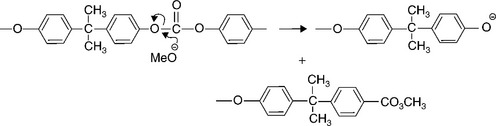
It is the hydroxyl ions (OH−) of the alkaline fluid which attack the carbonate group, the functional group in the polymer, as shown by the reaction mechanism of Fig. 5.33. It is well known that polycarbonate is sensitive to alkali degradation and stress corrosion cracking in alkali, and our experiments really took the phenomenon to an extreme. The research programme highlighted the sensitivity of polycarbonate to alkaline degradation with very rapid attack by many reagents. The same research was extended to other engineering polymers and showed how others were similarly susceptible to hydrolytic degradation, such as aramid fibre and PET in concentrated sulphuric acid, and polyimide in hydrazine, for example.
The polishing method proved valuable in being able to polish a battery case away and so study the variation of birefringence with depth through the thickness of the box, and it confirmed that much of the unwanted orientation occurred in the surface layers where attack from the solvent welding treatment could initiate (Figs 5.34 and 5.35). But the key issue of reducing lamp failures was to tackle the problem at source, at the moulders.


5.6.7 Moulding conditions
The quality of the boxes was highly dependent on the moulding conditions used by the trade moulder. The moulder was asked to produce boxes under different tool temperature conditions so that we could study the birefringence of the polymer, especially in relation to the solvent welded zones.
The trade moulder said that he used a tool temperature of 60–70 °C, which was at the very lower end of the manufacturer’s (General Electric Plastics, USA) recommended a lower limit of about 80 °C. We asked that he mould transparent cases at up to 110 °C so that we could track any changes in properties.
The results showed a dramatic decrease in chain orientation and also gave an insight to the distribution of orientation across the case thickness (Fig. 5.36). Samples from the base near to the gate of the box gave the highest strains, while those from the top the lowest, an expected result because orientation is always greatest near the gate, where molten polymer is forced into the steel tool. The equivalent frozen-in stress, σ, can be calculated with the equation:

where r is the retardation (metres), Q the stress optical coefficient and d the sample thickness. The values shown along the length of the box (Fig. 5.35) show how the stress is greatest at the surface everywhere when compared with the centre of the moulding, just the conditions which promote environmental stress (or strain) cracking. In a similar experiment, the tool temperatures were compared (Fig. 5.36). They showed how increasing the temperature lowered the degree of orientation quite dramatically, especially at the base. Essentially, increasing the tool temperatures allows the chain molecules to relax more easily to an equilibrium state, rather than being quenched into an unstable state
The solution to the problem thus took several forms, including change to the material (red to cloudy black), improving the adhesive and increasing the temperature of the tools. But there was another recommendation, which was perhaps the easiest to implement of all. It concerned the notch sensitivity of the polymer.
5.6.8 Stress concentrations
While surface scratches could lower the product strength, much more important was the fixed geometry of the design itself. Because polycarbonate is notch sensitive, any sharp corners will act as serious stress concentrators, and those points will be the weakest parts of the structure. And the design exhibited numerous sharp corners when examined closely. One important criterion for testing the design lay in a drop impact test, which mimicked the use a battery might experience in use, when dropped accidentally in the lamp room, for example. The interior corners at the base are critical because they lie behind impact zones and could initiate brittle cracks if the outer corners impacted the ground.
The stress concentration Kt, is simply the ratio between the real stress at a point, σmax and the nominal applied stress, σnom:
The standard compilations like Peterson did not have the relevant diagram for internal corners, but a paper had been published which did just this (19) and so could be used for estimating the stress concentration of an internal corner (Fig. 5.37). For the geometry of the box, then the key variables are d (wall thickness), h, the floor thickness and R, the radius of curvature at the corner:

so h/d = 4.0/3.5 = 1.14. The set of stress concentration curves could used to evaluate the factor Kt for various radii of curvature at the corner given this value of h/d, the horizontal axis in Fig. 5.37. In the first design of battery box, R was 0.1 mm, so
Taking the extreme value of h/d = 1 at right in Fig. 5.37, then the relevant curve lies above the highest curve of R/d = 0.1, and gave Kt approaching a value of 2. The boxes were then modified to a radius of 0.4 mm, which gave
This yielded an approximate value of Kt ~ 1.3. To obtain an estimate of the radius for no stress concentration, then Kt = 1 when R/d = 0.25, so
So analysis suggested that the minimum radius of the lower corner should be about 0.6 mm. This value could easily be achieved by simply smoothing the sharp corners of the core of the tool (that part which creates the shape of the interior of the box) using emery paper, not a costly operation given the importance in increasing the strength of the product.
It proved difficult in convincing moulders that sharp corners lowered the strength of the boxes until one of us challenged one of them to test a new case for himself by smashing the base with a large hammer. When it cracked, he appreciated the problem, and the radii were changed. Brittle cracks from the base inner corners were common at that time (Fig. 5.38).

5.6.9 Practical applications
Another example of the importance of minimizing radii came with a failed lamp which we were asked to analyse in 1979. The battery was relatively old, which was encouraging because it suggested that most batteries were by then starting to achieve their specification life of 3 years. This time, the battery had failed from one end by splitting along a vertical seam produced by mating of the tool parts (Fig. 5.39). The positive or active plates had expanded and put the ends of each cell under internal pressure, so that the ends distorted and eventually cracked along the weakest part, the small sharp corner at the seam. The inner surface was pitted where the holes in the protective sleeve around the plates had met the surface. The chemical attack of the material had been made by the lead dioxide (a powerful oxidant) extruded from the holes and making contact with the polymer surface. The pendant methyl groups in the bis-phenol part of the repeat unit were probably oxidized, and the chains split here rather than at the carbonate group. They formed the deep etch holes seen in the sections (Fig. 5.39). The boxes cracked along the sharp corner in the tool mating line, where tool wear had created the mismatch. The tool had made up to about 700 000 polycarbonate boxes and was showing its age. It was replaced with a new tool incorporating the latest design modifications we had recommended, and the lives of batteries increased from the low initial lifetimes.

Belt loops were another weak zone in the design where brittle cracks developed, and were encouraged by local high orientation (Figs 5.40 and 5.41). External cracks such as that shown grew on the outer surface but could grow through the thickness and so produce a leak of the electrolyte. So the final stage in making a safe casing was to ask the toolmaker to remove sharp corners by radiusing the tool. Since the steel tool forms the cavity within which the product is made, sharp corners in the product can be ameliorated by rounding sharp corners on the core of the steel tool, a simple and inexpensive procedure. The modifications produced a significant increase in impact strength.


Indeed, we built test rigs designed to drop full batteries onto a concrete floor, and the drop height increased considerably as the new modifications were introduced. We also introduced a new method, a drop ball test, where a cast iron ball was dropped from various heights onto cases or batteries. The cast iron balls were actually cannon balls kindly lent by the Woolwich Arsenal, and they also increased in weight from 7 kg initially via 10 kg to 20 kg. The impact energy, E is just mgh, where m is the mass of the ball, g the acceleration due to gravity (9.81 ms− 2) and h the drop height. So a case which survived a drop impact of a 10 kg ball from 2 metres possessed an impact energy of 196 Joules. With the improvements in design and moulding, the later cases were well capable of withstanding such high impacts, showing that the intrinsic strength of the material could be achieved when well made with a robust design.
5.6.10 Colliery experience
The change in fortune of the first new design of the T type batteries was shown by the records we obtained from two Lancashire collieries, Parsonage near Wigan and Sutton Manor, near St Helens (Fig. 5.42). Although the design life was 3 years, most batteries failed in the first months of use, and there followed a steady number of failures, with none surviving beyond about 2 years. However, as the bonding improved and testing of key components was introduced, the lifetime began to improve steadily (Fig. 5.43). However, the record of the red cases was still rather poor, with most failing to reach the scheduled full life. By 1976, new black cases were starting to replace the red cells, and the life of the batteries increased yet again (Fig. 5.44).


It was shown by records of the South Yorkshire region of the NCB, and which were part of a memo sent to the Senior Inspector of Mines (Table 5.1).
Table 5.1
Increase in battery life (numbers in parentheses)
| Black cells | Red cells | |
| Nov 1977–Jan 1978 | 1.04% (7 877) | 9.3% (3782) |
| Feb 1978–April 1978 | 1.93% (9 079) | 8.42% (2612) |
| May 1978–July 1978 | 2.99% (10 664) | 12.56% (1879) |
| August 1978–Oct 1978 | 3.78% (11 369) | 16.5% (966) |
| Nov 1978–Jan 1979 | 2.66% (11 578) | 7.77% (479) |
So the black cells were replacing the red cells during this period and showing a much lower failure rate, although there was still substantial room for improvement. At this stage we were recommending ameliorating sharp corners both externally and within the product, and they increased the reliability of the lamps yet further. Moreover, we met several electrical engineers and lamp room managers, who all reported favourably on the new design in smoky black polymer compared with the red cells. There were several new design modifications needed, however.
5.7 Improving design to prevent failure
So the various modifications in material, design geometry and manufacture produced a safer product, although further changes were made in the light of other problems. The belt loops required strengthening in the light of loop fractures in the pits and, in a redesign, were increased in width as well as being buttressed and all corners being well rounded. The several trade moulders involved in making the cases and lids were visited to impress on them the importance of using hot tools, as well as using simple quality control tests to ensure that chain orientation was minimal. An obvious test was to use crossed Polaroid sheets to examine the birefringence of box parts. Then, when everyone thought that the problems were over, new failures occurred separately in Australia and in South Africa.
5.7.1 Alleged hydrogen explosion
An incident had occurred in the Pasminco mine in New South Wales in 1989. The battery was maintenance-free, so there were no windows in the case. It was said that the battery had exploded, a very dangerous occurrence in a mine, so a thorough investigation was needed. The damaged battery showed loss of a chunk from the front face (Fig. 5.45), and it was possible to show how the failure had occurred by careful examination of the pattern of cracks. The failure started at the lid-box joint with two cracks travelling down into the box, although a third crack had been initiated much further down the face. It had originated on the interior of the box so must have been caused by a blow to the front. There were two crack intersections (I1 and I2) where the two sets of cracks had met (Fig. 5.46). The box had also been painted using a spray can, and tests on sprayed polymer showed it to be weakened by the treatment, although it did not initiate the cracks in the Pasminco battery. Paints have a carrier fluid, a light organic solvent, which can initiate ESC cracks, and there had been a series of road accidents where polycarbonate crash helmets had failed in a brittle way, having been spray painted (20).


An independent test with a new battery used a spark plug inserted into the case to explode the gas mixture. It produced similar brittle cracks, although the plates of the failed product showed no short circuits. In addition, a spray painted box was tested and failed through paint-induced cracking. It was concluded that the failure was not caused by an internal explosion, but rather by an external impact, which must have been of some force. The exercise was valuable in pointing out the hazards of spray painting the lamps, and the company in Australia advised to cease the practice.
5.7.2 South African lamps
A subsidiary of Oldhams in South Africa produced lamps for their extensive mining industry. Working conditions in some of the deep gold mines were severe, and the base of their battery was protected by a rubber boot fitted to the base of the box. We were asked to compare the design of the case with those made by two trade moulders in Britain. The South African battery was maintenance-free while Oldhams were still using top-up cells, although the window had been reduced to a small hole in the front of the case, with the non-spill device welded from the inner rear of the box. The semi-transparent faces of the battery cases were compared using strain birefringence. The comparison showed the high levels of frozen-in strain in the African battery and the lower level of the well-moulded British case (Figs 5.47 and 5.48). In order to forestall failures of the former, it was decided to provide trade moulders with a standard set of birefringence patterns against which they could judge box sections. When visiting new moulders needed to make extra cases, such a test was shown as a way of judging moulding conditions to achieve the best properties from the product.


What proved most difficult was to convince toolmakers that removing or ameliorating sharp corners in the product would also be beneficial. It seemed to run counter to their perceived wisdom, where sharpness probably equates with crispness and even aesthetic delight. They clearly do not see the product their tool makes. The investigator had to demonstrate the poor state of the boxes by smashing the base with a sledgehammer, and challenging the toolmaker to do the same. And it is by no means an attitude restricted to toolmakers of lamp products, as other cases elsewhere in the book describe. Common examples where sharp corners weaken products include screw thread roots, shoulders, holes, recesses, and numerous other design geometries. Although they may be needed for product function, all need careful design to minimize the inevitable stress concentration.
5.7.3 Further developments
For example, the use of a semi-transparent case allowed users to monitor the condition of the cell plates. Owing to the impact and wear the case received in use, shedding of the plate materials occurred, leading to an accumulation of powder lead sulphate at the base. It gave rise to concerns among lamp room supervisors, who complained to the manufacturer. While there was loss of capacity, the batteries still had reserve power and so were still serviceable. However, the company developed PVC bags to surround the plates, a device which simply collected the powder shed by the plates and didn’t tackle the basic problem. Out of sight is out of mind.
A much more important development has been the incorporation of methanometers in the headlamp, so giving every user advance warning of dangerous amounts of methane gas in the immediate environment. Methanometers have long been standard equipment for pit deputies, although most still carry flame safety lamps for back-up. The height of the ‘blue cone’ when methane burned within the lamp gives a direct measure of the methane content in the general air. There was some reserve in the new battery which could be used for powering such a device. It would improve the capability of the lamp in protecting the individual miner. But like the development of the new battery, there would be a long development phase needed to ensure that it, too, would be capable of resisting the severe working environment of pits. The existing Bakelite casing of the headlamp needed redesigning for insertion of the sensors, and extra inserts were needed for the battery lid for the associated electronic circuitry. The headlamp itself was redesigned in thermoplastic materials, with several problems of compatibility and moulding defects encountered. Thus a screw thread rim for holding the cap glass in place suffered failures due to the stress concentration at the thread root, and the tool was modified accordingly to prevent further failures.
The process of changing the design and manufacture of the miners’ lamp lasted several years, and was ultimately successful in reducing failures so as to make it a safe and reliable product. In hindsight, most of the problems could have been anticipated by research and development before the new lamp was introduced into the pit environment, and so prevented the unac-ceptably high failure rates. Although polycarbonate was not a completely new material in the 1970s, experience with both manufacture and use was very limited and designers were not aware of the limitations of the polymer in moulded products. The most serious limitations included the notch sensitivity of the product and its sensitivity to ESC, environmental stress cracking, especially with high levels of chain orientation.
By the time a reliable product had been developed, the coal industry itself was in serious trouble following a divisive miners’ strike, and demand dropped. However, the product was licensed to manufacturers in India and South Africa, for example, where underground mined coal has grown as the British industry has declined. The lamp is widely used in deep metal mines such as the gold mines of South Africa, and the coal mines of India. But the company itself was absorbed by Hawker-Siddeley, and then closed entirely in 2002, partly because of the poor factory conditions, the problems of working with lead and its highly toxic compounds, and the competition from battery makers in the Far East. The Chinese, in particular, have developed impressive mining products such as miners’ lamps for their rapidly expanding coal mining industry, and the latest models incorporate metha-nometers as well as small radio location devices which enable managers to pinpoint individual workers. Lithium batteries are also now being used for their greater power to weight ratio.
5.8 Conclusions
The development of new polymers and their application to safety-critical products has not been easy. Many mistakes were made in design and manufacture, resulting in numerous product failures. However, traditional materials such as hard rubber also presented severe quality problems, and the new materials were far superior when made correctly within appropriate design limits. Battery cases are effectively containers for chemical reactors, and must resist all that happens within, as well as the often highly corrosive electrolytes. The demands on the product have increased greatly as personal computers and mobile phones have become commonplace, and internal explosions have raised further problems of product integrity. The strength of the container presents the designer with a dilemma: most of its time, the container will be protected within a compartment and suffer very little stress. However, moving the battery raises the possibility of impact blows from falling, for example. Moreover, if the contents explode or expand, then the case will suffer, and expose the user to possible injury. Great care is thus needed in the choice of material and the way it is shaped, as well as the geometrical details of the product.
5.9 References
(1) Brydson, J. Plastics Materials, 7th, Butterworth, 1999.
(2) , Open University (T838). Data Book. Design and Manufacture with Polymers, 1999.
(3) Joseph Lucas (Batteries) Ltd, Another-v-Gaedor Ltd. Reports of Patent cases (RPC). 1978; 10:297–396.
(4) Bone, W.A., Townend, DTA, Flame and Combustion in Gases Chapter XIX. Longmans Green and Co, 1927:217.
(5) Van Krevelen, D.W., Properties of Polymers, 3rd. Elsevier, 1990:732.
(6) Examples are shown at http://www.tractorshed.com/fordnclub/npic6856.htm and http://www.rayvaughan.com/battery_safety.htm with descriptions of the incidents.
(7) The site at http://www.indpwrbattery.com/hydrogen.aspx describes such an explosion.
(8) http://www.nasa.gov/vision/earth/technologies/hydrogen.html discusses the use of hydrogen in space exploration.
(9) University, Open, Forensic Engineering (T839), Block 3 Catastrophes, 2000.
(10) Trimble, S. Report of AirshipHindenburg. Accident Investigation, Air Commerce Bulletin. 1937; 9(2):21–37.
(11) Bain, Addison, The Freedom Element: Living with Hydrogen, 2004. [Blue Note Books].
(12) , HM Factory Inspectorate. The explosion at Laporte Industries Ltd., Ilford. 1975. [HMSO (1976), 5 April].
(13) , Duckham, Baron and HelenGreat Pit Disasters: Great Britain 1700 to the Present Day. David & Charles, 1973.
(14) Oldham, C.E. Vintage Centenary Issue. Oldham Batteries Ltd; 1965.
(15) Lewis, P.R., Ward, R.J. Polishing, thinning and etching of polycarbonate. J Colloid and Interface Science. 1974; 47:661.
(16) Doi, M., Fujimoto, K., Kobayashi, S. Etch Pit Formation Model During Chemical and Electrochemical Etching in Polycarbonate Foil. Radiation Protection Dosimetry. 1991; 37:5–12.
(17) Mills, B., Jones, H., Leak, G.M. Thermal grooving in 3% silicon-iron. Metal Sci J. 1967; 1:9.
(18) Wagner, C. Contribution to the Theory of Electropolishing. J Electrochemical Soc. 1954; 101:225.
(19) Allinson, I.M., Bacchus, K.M., Design of internal load bearing flanges, Paper 13 in Experimental Stress Analysis. Proc 4th Int Conf on Experimental Stress Analysis, IMechE, Cambridge (1970), 1970.
(20) Mills, N.J., Plastics: Microstructure and Engineering Applications, 3rd. Butterworth, 2005.