
Polymeric pipes and fittings
6.1 Introduction
The pipes that transport fluids between reservoirs are not dissimilar in the problems they present when failure occurs. Fluid leaks can cause substantial damage to property, and are often more insidious than the sudden flood that comes when a container fractures. They can thus go unnoticed until the leak triggers an accident or a fire, for example. Like containers, polymers have been widely adopted in many product applications, especially in the distribution of utilities like water and gas, the disposal of waste water and sewage, and in communications (such as carrying fibre-optic lines). They are much lighter to manhandle and are usually tough enough to withstand rough treatment during installation (1). They do not suffer the problems of corrosion that afflict steel pipes, and are generally of a low enough cost to be feasible for replacement lines when conventional distribution systems are renovated, for example. They may also be used to line existing pipes. Polyethylene and PVC are two of the most common thermoplastics used for piping, but others such as ABS are also used in special applications like pressurized air systems. Growth in their use has been very high in all nations of the world over the past two decades, either for replacement of older systems in conventional materials like cast iron, steel and earthenware, or for entirely new networks. When fractures occur in buried pipelines caused by internal pressure, of whatever material, the cracks tend to run along the axis of the pipe, and must be replaced at great cost since long lengths of pipe may have been destroyed.
However, plastic pipes are sensitive to certain organic fluids and if they contact a stressed part, environmental stress cracking (ESC) can cause sudden and quite unexpected fracture, sometimes with disastrous results (2). When polybutene pipe was adopted for domestic hot water systems in the USA, for example, there were numerous failures from stress corrosion cracking (SCC) such as by oxidation (3). Plastic pipe can also suffer creep when imposed external loads are excessive for one reason or another, especially when the foundations move or when loads above buried lines increase.
The fittings that accompany pipe systems are usually, but not always, constructed of the same polymer. Failure of or at joints is often more likely because joints are frequently injection moulded and thus inevitably of lower molecular weight and therefore of lower strength. They exhibit inevitable stress concentrations which magnify the overall stress at such features, so fittings such as bends, collars and two-way joints represent the weakest points in most load paths. Fittings are attached either by thermal welding (e.g., polyethylene) or by using a solvent cement, as in ABS and PVC. Welding of either type needs special care to ensure a tight, reliable and leak-proof joint.
6.2 Fracture of PVC water piping
When large water mains fracture, substantial damage can occur as the water floods out, as many road users will testify by the inconvenience when they break under, or by the sides of roads. The original water network was largely created during the Victorian period with the growth of industry and its great thirst for water supplies, closely followed by the demands from domestic users for clean and potable sources. Most of the original network utilized cast iron pipes of substantial construction, some of which is still in use today, although being replaced by thermoplastics as investment in the infrastructure improves. Cast iron is a very brittle material, and failures are frequent when the overburden on buried pipes changes for whatever reason, or when broken by careless workmen installing other systems nearby, or when water inside a pipe freezes. The expansion when the temperature rises splits the pipe (4). Utility companies frequently follow similar paths when supplying towns and cities, and they may not always coordinate their knowledge of their own network with those of other companies. As thermoplastic pipes replace older systems, there is a problem of compatibility of the new with the old: the properties of the former are quite different from cast iron or steel, especially in the loads that can be used safely on such pipes. Where two different systems meet then failure can occur at the junction, as the following case illustrates.
6.2.1 Factory crisis
We were approached by the insurers, General Accident, when a factory in Flitwick, Bedfordshire was flooded by a pipe fracture in 1985. Because the factory made and upholstered furniture, the damage was very extensive, the water ruining much of the stock. The claim on the insurers was therefore large, and the insurers needed to know the cause of the failure.
The accident happened at 7.00 am on 16 October 1984 when a rising main suddenly fractured and released a large volume of water into the factory. Thirty workers were there at the time, so discovery was immediate, and one operative nearby was knocked off his feet by the force of the jet of water emerging from the broken PVC pipe. The pressure was sufficient to flood the premises with 4 inches of water in a few seconds, and the jet destroyed work in progress, sewing and cutting machines. Although they were able to turn off the sprinkler main within a few minutes, much damage had by then already occurred.
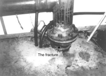
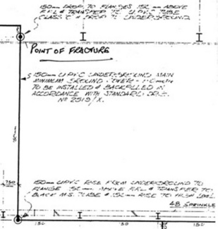
The loss adjuster reported that the 6 inch diameter plastic main had broken about an inch above the concrete floor where the main emerged from the buried pipe line, in a Polaroid photograph taken by the adjuster after the accident (Fig. 6.1). The fracture occurred in a joint with a steel pipe above via a flanged junction. The system had been in place for about 7 years, but about 3 months prior to the accident, a tail end air valve was fitted to the steel pipe above the flange junction (Figs 6.2, 6.3). The joint was formed by bolting the two flanges together. An identical rising main without an air valve in an adjacent room remained intact, suggesting that the new fitment was associated with the failure. The loss adjuster thought that the failure had been caused by fatigue, but he failed to provide any supporting evidence for his theory. The water was at an internal pressure of 7 bar, but was completely still, ready for use only when the sprinklers were activated by fire. Each rising main was connected to a pipeline buried about 1.2 metres below the concrete floor (Fig. 6.4).


6.2.2 Analysis of broken pipe
The examination of the fractured PVC pipe (Fig. 6.5) was clearly essential to explaining the failure. When the end had been removed from the steel pipe, and the buried part removed by breaking up the concrete bed, it was essential to match the parts to see if anything could be gleaned about the stresses on the pipe.

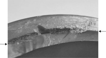
There were several points of interest in the fracture itself. In the first place, the fracture was entirely brittle and secondly, the cracks were circumferential, which meant that it was not the high internal water pressure which caused the failure, since pressure failures always occur along the length of the pipe rather than circumferentially. The fracture was rather complex, partly because the pipe end had been damaged by picks used to extract it from the concrete in which it had been embedded. However, those parts which had been damaged were relatively easy to distinguish from the original cracks.
But what did the fracture surfaces show? It was possible to follow the cracks as they ran around the pipe from such details as crack intersection and chevrons (or hackles) and to infer that the fracture probably started at the stress concentration of the flange shoulder where the pipe had been solvent welded to the injection moulded flange (Fig. 6.6). The cracks grew along the shoulder at two zones (Figs 6.7, 6.8), deviating into the pipe under a shear stress. Defects were present in or close to the corner of the solvent welded joint between the collar and the pipe, and the latter appears from crack junctions to have been the first to have propagated. The growth of two cracks had formed two cusps where they met (Fig. 6.5).


The stress concentration diagram provided by Pilkey (5) provided an indication of the magnitude of the effect at the shoulder radius. Since t= h and t/h = 1, the centre line applies, but what was the radius at the external corner? The wall thickness was 6.9 mm, and the radius of the solvent weld varied from less than 1 mm up to perhaps 2 mm. The maximum value of t/r was 4 so the minimum radius on the graph is 6.9/4 = 1.725, with a Kt factor of 2, so the minimum stress concentration factor was about two.
6.2.3 Reconstruction
The two major parts could be matched together so as to reconstruct the pipe before fracture, using a blow-up of the loss adjuster’s photograph on which to base the reconstruction (Fig. 6.9). The original parts mated very roughly but there was some distortion of the pipe as well as parts missing from the fracture. Using the elliptical shape of the parts in the original photograph, the broken ends were reconstructed as shown in Fig. 6.10. The picture showed that the broken ends had separated and twisted with respect to one another. The white marks were used as a datum line, showing the degree of twist between the two parts. The displacements were:


So the rising main had been under significant tension and torsion just before the final failure. But what were the stresses and how did they relate to the known strength of the material?
6.2.4 Stresses on pipe
To consider all of the stresses acting on the pipe, it was necessary to consider the internal pressure as well as the tension/torsion from an unknown source. In all pipes, the hoop stress (σH) is twice the longitudinal stress (σ1) when pressurized (Fig. 6.11):
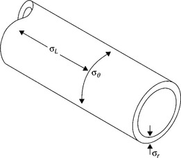
where P is the internal hydrostatic pressure, D the mean pipe diameter and t the wall thickness. Since the internal pressure was 7 bar or 0.7 MPa, the mean diameter of the pipe was 161.1 mm with a wall of 6.9 mm, the wall stresses are thus
The hoop stress was well within the strength of uPVC, but the imposed strains were quite different in magnitude. Assuming that the pipe was buried by 1.2 m, then the tensile strain was simply
Using book values for the creep modulus with time (6), then
The short-term strength of the PVC (using samples cut from the pipe) was measured directly in a tensometer and the strength at yield was
The material was tough and ductile, showing that it had not degraded in any way (a result confirmed by FTIR spectroscopic analysis).
The toughness was also measured directly on pipe material from single edge notched specimens, giving a value of
a value in line with literature estimates and comparing well with those mentioned in the previous chapter. The total tensile stress on the pipe before failure was thus at least
With a stress concentration at the shoulder of the joint, that gives a total stress of at least 60 MNm− 2, a value in excess of the short-term strength of the material, and explains why the overloaded pipe suddenly fractured.
6.2.5 Cause of failure
So our conclusions were reasonably clear: that the sudden fracture and ensuing flood was caused by excessive tension and torsion in the PVC pipe prior to the final event. But what created the overload? It is reasonable to suppose that the fitment of the air valve created the torsion, especially if the end of the steel pipe fitted to the side of the valve box had not coincided with the entry point. It would have then been possible to twist the valve box slightly to ensure connection of the joint. The geometry shows (Fig. 6.2) that a leverage action could have been used, and the twist taken up by the most compliant part of the system, the PVC pipe. However, that still left the tension in the pipe unexplained.
One possibility could have arisen from the original fitment of the rising main. It would have been laid first with the concrete floor, and the plans show that it was laid on a bed of sand in a trench within the concrete. The trench was about 4 feet below ground level. Although the exact details of the way the system was installed are unknown, it is likely that the plastic pipe system was laid first, followed by the steel sprinkler system in steel above, and then the two bolted together. Water would then have been allowed to enter the system, and it is at this stage that major stresses were imposed on the pipes. First of course there would have been the hoop and longitudinal stresses from the water pressure, but there would also have been a substantial load from the column of water acting on the vertical pipe and the water present in the horizontal main below the floor. If the sand foundation settled over time, then the column would have tensioned the PVC pipe to criticality.
Failure of foundations is common with pipe systems, where shifts in sand footings can leave pipes unsupported and so put weak joints under severe strain. Mixing pipes with greatly differing properties is a problem because the less stiff or weaker pipes will take all the resulting stress, increasing the likelihood of failure by overload.
6.3 Failure of PVC water pumps
PVC is used very extensively for water supply in the developing world where there have been problems in producing high quality pipe. One critical use occurs in rising mains for handpumps. They are a primary source of drinking water for villages, especially in Africa, India and other parts of Asia with large rural populations. Much research has been undertaken by charities such as Oxfam to improve the design of hand pumps, and several standard products are used widely across the world, such as the Afridev and India Mark II. Their importance in attempts to bring clean water to rural populations cannot be over-stated (7). Further attempts have been made to improve designs for VLOM (village level operation and maintenance) so that worn parts such as bearings can be replaced easily and quickly, for example. PVC pipe is used both for networks and rising mains in wells since it is reasonably tough, light for ease of installation and of relatively low cost. It is also a relatively stiff polymer compared with HDPE, for example, so less effort is wasted when drawing water.
But problems have been encountered where local stresses are high, especially in rising mains where all of the load is concentrated at the top where it enters the pump. One of the most common types of hand pump involves a reciprocating lever which moves a pump rod up and down within the main. There is a non-return valve at the bottom of the well immersed in the water, so that at each stroke when the pump is primed, water is pulled into the empty main and rises at each stroke. The water rises steadily until it reaches the outlet at the pump and is collected. So when not in use, the rising main is supporting the load of a full column of water ready for next use (Fig. 6.12).

Although steel has been used extensively, rust is a big problem and can clog the valve at the base, as well as cause stress corrosion cracking at threads in the joints between pipe lengths, and so lead to loss of the main down the well. PVC mains have also failed, and causes loss of the water supply until the equipment is repaired. It is not at all easy to fish a fallen pipe from the borehole (not much greater in diameter than the main itself), so failure has serious consequences for the villagers who rely on the well for their water supply. If they return to use polluted rivers or streams, disease can follow rapidly. The danger of cholera, for example, is seen by the 2008 epidemic in Zimbabwe, where water supplies broke down across large areas of the country.
6.3.1 Rising mains
We conducted research designed to explore the failure mechanisms of rising mains, research funded by the Consumer Laboratories and the World Bank in the 1990s. It produced results which shed some light on some unexpected failure modes. As the previous case study showed, PVC is welded using a solvent, or rather a solution of PVC in a suitable powerful organic solvent. Extrusion of the pipe itself can cause problems, and some skill is needed in producing the best quality, especially for the demanding role in rising mains. The process involves extruding PVC powder into pipe, and care in temperature control is vital to ensure the strength of the final product. The particles must fuse together to form a uniform material without voids and other defects. A simple test for determining the quality of fusion is to immerse a tapered section of pipe in methylene chloride for about 20 minutes. If fusion is poor then the pipe surface becomes granular and whitening occurs. Most samples showed granulation and whitening with very few showing correct behaviour like the central sample in the figure. Samples from a selection of different developing countries showed a wide range of behaviour, those at left and right showing whitening and granulation in Fig. 6.13. GPC analysis showed a range of molecular weights indicating different sources, as one might expect. PVC also degrades at high temperatures to form hydrochloric acid gas by the reaction:

and the double bond will oxidize to form carbonyl groups within the long chains. They are points of weakness and can be detected using FTIR spectroscopy. In fact, carbonyl levels were found to be low in all the pipes examined.
So the most serious defect found in the samples was insufficient fusion of particles. While it might not affect pipe used for low pressure water supplies, it can affect the fatigue lives of rising mains. The effect can be estimated from the Paris equation (8):
where Nf is the fatigue life of pipe cycled at 1 Hz and a0 is the maximum flaw size (m and K are constants). The stress range (Δσ) is 5.4 MNm− 2 for a pipe lifting water from 45 m. For a flaw size of 1 micron, then Nf is 3.8 × 10⁷, but if a flaw size of 100 microns occurs, then the fatigue life drops to 6.7 × 10⁶. So the occurrence of much larger voids between particles lowers the fatigue life by a factor of about six. It was thus recommended that pipe manufacturers took much greater care in making pipe dedicated to rising mains, although further tests showed that the joints needed even greater care.
6.3.2 Fatigue tests
As part of the intensive tests to which rising mains were subjected, we tested a jointed pipe under realistic fatigue conditions. We used a frequency of 80 cycles per second and a stress range of 10.8 MNm− 2 with a mean of 5.4 MNm− 2 under sine wave cycling. The pipe failed at only 1.3 × 10⁵ cycles, much lower than might have been expected, and it failed not in the pipe itself but rather at the joint. It had been solvent welded by others for our test, and rather than fracturing, the joint was pulled apart at the weld (Fig. 6.14). The joint had been very poorly bonded and a simple measure of the unbounded area was made by tracing the bond out and then weighing the mass of paper cut-outs. It turned out that only 23% of the total area available had been bonded, so making the joint much weaker than expected (Fig. 6.15). Fatigue cracks had started not in the numerous stress concentrations of the bond itself, but rather at the outer corner where the pipe joined the socket (Fig. 6.16). Microscopic inspection showed that the pipe itself was also poorly fused at this point, so external defects were aided by internal voids between the particles. Another surprising feature of the failure also emerged: the pipe and socket did not form a regular but rather an eccentric joint, so solvent welding was inhibited from the outset of forming the bond between them. It was the pipe itself which was eccentric to the extent of about 1% on its diameter, giving a joint gap of between zero and 0.55 mm, the socket having an eccentricity of only 0.1%.


So the strength of rising mains was (as expected) dependent on the quality of the topmost joints. There is a standard for making such joints (9), which recommends in great detail the procedures to be used. It is vital that fresh cement be used, and the surfaces to be joined carefully abraded before applying the cement to ensure total wetting. The joint must be allowed to dry, necessarily a long process since all solvent must diffuse away from the deepest parts before the joint is fully dry. A further survey of solvent cements from around the developing world also showed great variation in the solvent, added polymer and composition.
One of the problems in performing such research was its worldwide nature. It was clearly possible to obtain samples of new pipe and cement, but obtaining failed or fractured pipe and fittings was much more difficult owing to the natural tendency to discard failures when installing replacement rising mains. However, great improvements have occurred in the design and standardization of hand pumps in the developing world, especially where good practice spread from countries such as Sri Lanka to India and Africa. PVC pipe manufacture reached a high standard in the 1990s and many villages benefited from the high quality of installations in the countryside.
6.3.3 Machined PVC problem
A rather unusual application of rigid PVC involves building apparatus from machined parts, largely because the polymer is very easy to machine into complex and intricate components. A company in Coventry had the idea of building a wrapping machine using such PVC components. Their concept included incorporating water cooling channels within the PVC parts to control the process. They built a working prototype using a combination of light alloy components, slab PVC and acetal bearings (Fig. 6.17), and relied on a toolmaker to machine the various PVC parts, solvent welding the parts together to make the inner water cooling channels. However, when the wrapping machine was first switched on in 1998, numerous leaks occurred from the PVC components and rendered the process inoperable.

The plastic packaging company sued the toolmaker for their losses. We were asked to examine various parts and report on the root cause of the problem. One particular part was chosen for close scrutiny. It was a bar 640 mm long with a section of 39 by 20 mm and when examined, proved to be slightly curved, being about 2 mm out of true. The bar had been solvent welded to form the water channel which ran along its length, and was drilled at either end (ID about 8.5 mm) to accept the water supply. Macroscopic inspection showed that the joint between the two halves exhibited a small gap of about 0.6 mm (Fig. 6.18). The same picture shows cross-threading on the upper part of the screw thread, no doubt caused by numerous attempts to discover the source of the leak or disconnect the supply to stop the leakage. Since the water pressure was about 2.6 bar or 38 psi, the inner source of the leak was established. External examination showed a similar problem, with similar sized gaps in the joint, and since the bar had leaked here in service, a path between the two gaps was present (Fig. 6.19). No doubt the many other leaks in the system were caused in a similar way by poor joints.

So how had the faulty joints occurred? Several possibilities can be suggested: poor application of the solvent cement so that not all the joint area was covered, poor cement or insufficient clamping of the parts as they were joined. The correct cement had been used so poor application and low clamping pressures seemed the likely explanation. On the other hand, some joints showed extruded cement, so clamping was probably sufficient. That left poor application without complete wetting of the surfaces as more likely, possibly made more difficult by distortion of the underlying material. The distortion may have been produced by asymmetric heating during machining, so one side of a part expanded to a greater extent than another. Alternatively, residual strains (chain orientation) in the original material could have been affected asymmetrically. We concluded that the parts should have been pressure tested before supply, and greater care should have been used during machining the PVC.
6.3.4 Mediation
The case was due for trial but, as is increasingly common nowadays, the judge asked for the experts on each side to try to agree a joint statement. While some points could be agreed, there was an impasse over the quality of machining, whether testing had been attempted and over the competence of cement welding. The defendant toolmakers maintained that they had performed their work to a high standard, despite the overwhelming evidence to the contrary.
The next step involved mediation between the parties, another increasingly common way of settling disputes before trial. It normally involves a barrister establishing the facts by meeting each party separately, and sitting in different rooms. The lawyer attempts to come to a view of the basic problems by asking increasingly sharp questions of each party. By progressively forcing the issues, the lawyer is effectively cross-examining each party on the credibility of their allegations, not in an open court but rather in complete privacy (and in the absence of the other party). The costs are high but much lower than a full trial, and confidentiality is maintained. The defendants were advised by an expert with little experience of polymers, and the damage to the PVC components could not be denied or explained away very easily. The case settled with compensation awarded to the packaging company against the toolmakers. It illustrated the importance of allowing for the properties of polymers during machining operations and achieving good welds by following good practice during adhesive bonding.
6.4 Failures in gas pipelines
Polyethylene pipes are now the norm for gas pipelines across the world, but their increasing use has not been without problems. Flooding from broken water pipes can clearly cause great physical damage and lives are rarely lost, but escapes of gas are much more serious owing to the risk of explosion. Traditional materials like cast iron and steel have been the cause of many gas explosions, whether through brittle fracture of the cast iron, or by rusting of steel mains. Thus a gas explosion which killed four people from one family in Larkhall, South Lanarkshire, in December 1999. The owner of the buried pipeline, Transco, was fined £15 million for the accident in 2005. The failure was caused by deep corrosion of the ductile cast iron main (10 inch (25 cm) diameter), which the company apparently thought had been replaced by an MDPE gas main, such was the state of their records. While many such pipelines have indeed been replaced, there are still many in situ which represent a real hazard from leaks to the environment. Another explosion occurred on 22 October 2000 on Linfield Street, Dundee and it was traced to a fractured joint on the 4 inch (10 cm) cast iron main (10). Two people died and the investigation showed several previous gas leaks had occurred in the vicinity. At the time of the report, Transco estimated that only about 50% of the old mains had been replaced by MDPE, and their replacement would be speeded up. The cause was probably subsidence due to ground movement from other excavations (e.g., drainage pipes) near the affected joint.
However, there have been several serious explosions from MDPE gas lines in which lives have been lost and large-scale physical damage has occurred in the USA, for example (11). The main problem is brittle behaviour in a polymer which is nominally tough and ductile. In its 1998 review, the NTSB described three such disasters, the first of which occurred at Waterloo, Iowa on 17 October 1994. The explosion and fire which followed the escape of gas killed six people and injured seven more, destroying a building and damaging several others in the vicinity of the gas escape. In another accident in San Juan, Puerto Rico in November 1996, 33 people died while one person died after a gas explosion in Texas in 1997.
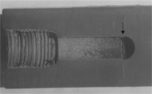
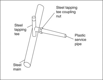
The Waterloo explosion occurred after gas leakage from a junction between a ½ inch (12 mm) diameter MDPE plastic service pipe and the steel main (Fig. 6.20). Brittle longitudinal cracks had grown from the junction, and eventually fractured finally, releasing gas (Fig. 6.21). The pipe had been made more than 20 years before, so crack growth had occurred over a long period of time (12). During the first introduction of the MDPE, testing simply involved over-pressurization until rupture, and ignored the problems of short-term brittle fracture by ESC, for example. Long-term life was predicted from short-term rupture experiments, and neglected to allow for the downturn in hoop strength at longer times (Fig. 6.22). It is a perpetual problem in many safety-critical products with testing regimes which seek to predict long-term behaviour from often very short-term tests. Such tests are even more critical in buried pipes where leak detection is inherently difficult, and replacement expensive and time consuming (as well as disruptive to road users, for example).


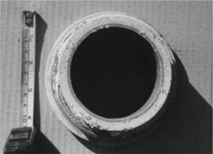
The huge explosion in Puerto Rico in 1996 was caused by brittle cracking of an MDPE pipe made in 1982 (Fig. 6.23). Propane gas escaped and pooled in an adjacent cellar, since, unlike natural gas or methane, it is heavier than air. Eventually a spark from an air conditioning unit ignited the gas with devastating effects (13). Brittle cracks were seen at thermally welded joints, where there was a stress concentration formed by the external corner (Fig. 6.24). The immediate cause of the cracking was ground subsidence beneath the pipe, so transferring greater loads from above onto the pipe junctions. A water pipe had been installed under the gas pipe a few years before the explosion and failure to backfill correctly allowed the gas pipe to bend, the loads at the joints being much greater than expected. The holding company, Enron Inc, settled compensation claims without a trial and without admitting liability. The final case discussed in the NTSB review report of 1998 was a gas explosion at Lake Dallas in Texas in 1997 (11). The cause was a metal pipe pressing on the plastic MDPE pipeline, which created a longitudinal brittle crack (Fig. 6.25).

6.23 Humberto Vidal store in Puerto Rico after propane gas explosion caused by brittle cracking of gas pipe.


Although the NTSB made several recommendations to improve testing of pipes, better control of weld formation and care where other pipelines existed or were later installed (including foundations), further explosions have continued to occur. The NTSB were, after all, recommending improvement of new installations, and there were numerous lines already in existence where problems could still occur. One such devastating explosion was at Dubois in Pennsylvania in 2004 (14). It destroyed a house and killed both occupants at 8.54 am on 21 August (Fig. 6.26). The cause was a gas leak from the butt fusion weld of a 2 inch (5 cm) diameter gas line to the house (Fig. 6.27). The joint had been formed six years before by the hot plate method, where the two ends are pressed flat against a hot plate, the plate removed and the two ends then pressed together. The NTSB found that the joint was ‘mitred’, or in other words, the ends were angled at about 2 degrees to one another, rather than being completely aligned with one another. The beads of molten polymer which form each side of a butt fusion joint should be uniform, but were asymmetric in this case.


6.4.1 Fracture surface
The fracture was examined in some detail using both optical microscopy and ESEM. The single origin was identified at one side of the weld, and had grown around the pipe along the line of the joint (Fig. 6.28). Voids were found at several parts of the surface, perhaps indicating that excessive temperatures were used, and so degrading the polymer. Alternatively, the two parts may not have fused sufficiently to have formed a good joint. The bond was formed from coiled pipe, more difficult to form a straight un-mitred joint correctly, and it was found that when 40 more similar joints were removed and examined in the vicinity, a high proportion were defective.

The NTSB concluded that the faulty joint was the root cause of the escape of gas and the deaths of the two residents of the house demolished in the accident. Unfortunately, the investigators were not able to ascertain the original position of the pipe, since the gas company had smashed part of the pipe near the failed joint. It seemed clear, however, that ground movement had placed the butt weld under severe stress for the fracture to have occurred.
The continued failure of gas pipes reflects all the problems of faulty welding often made many years before the pipe was made and laid, and suggests that all possible attempts should be made to detect any gas leaks very early so as to prevent catastrophic failures. The explosive power of even a small gas cloud released by a leaking pipe is so high as to demolish houses and other buildings completely, and casualties are likely in this scenario. While each accident may improve testing, construction methods and inspection procedures, there is a high likelihood that such unfortunate accidents will continue owing to the backlog of faulty pipes and joints waiting to fail. In the UK such explosions also continue to occur with distressing regularity, many it has to be said from corroding steel or iron lines which should have been replaced years ago. One hopes that the US experience will ensure that laying and welding methods used currently will inhibit further failures of plastic lines.
6.5 Failures in ABS pipes and fittings
ABS thermoplastic is also widely used for pipes in various applications. In one case, it was alleged that ABS pipework at a hydrochloric acid storage depot at Immingham docks could cause serious leaks by degrading in contact with acid. In another case, a large diameter ABS pipe used at a glass works exploded, causing substantial physical damage in the vicinity. In both instances, there was fundamental disagreement about the causes of the failures between the experts asked to investigate.
6.5.1 Immingham docks
The depot concerned stored concentrated (35%) hydrochloric acid ready for shipment to North Sea oil and gas fields for secondary and tertiary recovery of hydrocarbons (Fig. 6.29). The acid is pumped into old wells to attack the bedrock, and so improve its porosity, thereby allowing more hydrocarbons to be collected. The case was brought in 1999 following installation of the pipework in mid 1997 for conveying acid between the various storage tanks and the dockside. The case against the installer was based on a leak of acid at the plant, although no failed or cracked samples had been preserved. Various stained samples from the system were taken when concern arose over the polymer used. Several, but not all the pipes had been replaced by polypropylene, which was said to be more resistant to the acid than ABS.

The few samples which were available for examination included a blanking plate (200 mm in diameter and 20 mm thick) used to seal a dead end (Fig. 6.30). It was stained to a depth of about 0.75 mm, presumably by contact with the acid. DSC analysis showed that the effect of the contamination was to lower the Tg of the material from about 108 °C to about 100 °C. FTIR spectroscopy showed very little difference between intact and stained samples, although there was a small carbonyl peak detected in the contaminated sample. There was no sign of cracking or deterioration of its mechanical properties.

A polypropylene pipe which had been used at a similar storage plant in Great Yarmouth was also available for comparison (Fig. 6.31). It showed a similar zone of contamination (without cracks) and was analysed using the same techniques. DSC showed a small drop of only 2 °C in the melting point of 165 °C, but no difference could be detected in the IR spectrum, possibly because the method used hot decalin as solvent, so any volatile compounds present could have evaporated away.
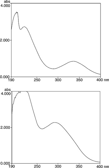
The next step involved spectral analysis of the raw hydrochloric acid stored at the site. Although none was made available immediately, the fluid is supplied commercially for cleaning concrete surfaces. One of the samples purchased showed a strong yellow colouration and so a sample of the acid was requested from Immingham. It proved very similar, with a deep yellow colour, not dissimilar to that shown by the contaminated zones. The colour suggested that UV spectroscopy could indicate the nature of the contaminant, and it produced a spectrum showing two peaks (Fig. 6.32). Ferric chloride is also coloured deep yellow, and such a compound could easily have been produced by reaction with iron pipes, for example. The UV spectrum showed peaks in quite different positions, so the contaminant of the acid must have been different in structure. The most similar compounds were phenolics, but could not be confirmed. The data sheet on the acid admitted the presence of various contaminants, including traces of free chlorine, but there was no visible cracking so SCC did not appear to be occurring in the ABS polymer. So we concluded that the colouration was probably caused by phenolics or other organic contaminants diffusing into the surfaces of exposed plastics from the acid, including both ABS and PP, with the effect of slightly plasticizing the polymer but with no other deleterious effects.
6.5.2 Conclusions
Another expert report concluded that ABS was unsuitable for exposure to the acid, using no direct evidence but rather data sheets of exposure. These are lists compiled and supplied both by raw materials suppliers and independent labs like RAPRA (who authored the report condemning ABS). They are simply lists of many different chemicals and the assessment of the effect on the polymers considered. But they can be based on old data, and neglect the development of better grades of polymers. RAPRA relied on one of their own lists, which was contradicted by other lists from manufacturers but of more recent date. However, support from some such lists could not displace forensic analysis of fractured samples, and it was likely that the failure could have occurred by another mechanism such as a poor joint or external impact and damage, for example. Since no records of the incident appeared to have survived, the case could not proceed very far without more direct evidence.
The conflict was eventually settled by mutual agreement, but it was interesting to observe that the pipework at the plant included both ABS and polypropylene, even after the dispute arose (Fig. 6.33). If ABS was so badly affected, then surely all ABS pipes should have been replaced. However, the interaction of different chemicals with thermoplastic materials must inevitably remain a topic of continuing research, since the downside can be catastrophic failure leading to loss of property, disruption to businesses and personal injury, as the following case shows.

6.6 Compressed gas explosion
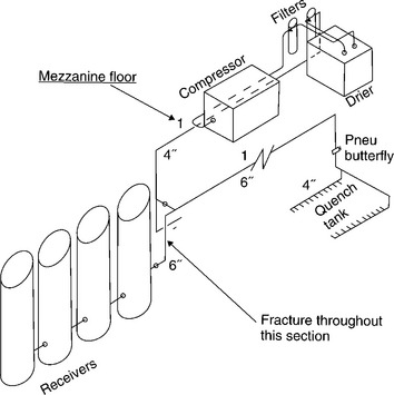
We usually associate explosions with escapes of flammable gases (hydrogen, methane, propane and so on), and while they are unfortunately not uncommon, it is also true that explosions can result from the sudden escape of any highly compressed gas, whether flammable or not. Compressed air is widely used in industry as a power source for pneumatic tools, for example, and compressed air is also used for quenching glass in the manufacture of car windscreens. The air supply is produced by a compressor connected to a set of accumulators, or tanks, from which the air can be tapped as and when needed to quench the glass (Fig. 6.34).
But on 2 October 1998, such a system suddenly exploded on an industrial estate in Winchester, the air release being sufficient to demolish an adjacent wall, and several BMW cars in the showroom on the other side of the wall were wrecked. The site of the explosion lay in a large diameter ABS pipe leading from the accumulators (Figs 6.35 and 6.36), one side of the pipe having ripped out during the event. There were also other longitudinal cracks in the same pipe, showing that growth of internal cracks must have caused the accident.


6.6.1 Cracked pipe
On inspection, the interior of the pipe (1.22 m long, 16.8325 mm in diameter and with a wall of 13.2 mm) exhibited numerous sub-critical cracks aligned along the axis (Fig. 6.37). The cracks appeared in swarms rather than being distributed evenly through the inner surface, and it was clear from the major fracture surfaces that one such crack had exceeded a critical size and grown suddenly to completion. The inner side of the cracks appeared entirely brittle while the outer side was white, indicating craze formation and a normal phenomenon in ductile polymers like ABS. The boundary between the two regions was very sharp and well defined (Fig. 6.38). In other parts of the pipe, the boundary disappeared as all the fracture surface was white in colour. The interior of the pipe showed traces of blue paint indicative of the blue painted exterior having impacted and scraped along the inside, presumably as a direct result of the explosion.


Optical microscopy showed how crazes could form at the ends of brittle cracks to form a shear band which could interact with adjacent shear bands. But other areas showed faint traces of superficial contamination with cracks initiated from the path of contamination (Fig. 6.39). Such evidence pointed to ESC caused by some unknown organic fluid which probably made contact with the lining of the tube just before the final event. Fatigue could be excluded as a cause of failure since there was no trace of striations within the crack surfaces. And any problem with the blue paint causing cracking could also be excluded since all the cracks and crazes were entirely on the inner bore.

6.6.2 Mechanics
No problems with the structure of the polymer could be detected by either DSC or FTIR spectroscopy, so oxidized or degraded polymer was excluded as a failure mode. The hoop stress of the thick pipe was calculated using the equation (15)
where q = the maximum pressure = 10 bar = 106 Pa = 106 MNm− 2, a = outside radius = 84.25 mm, b = inside radius = 71.05 mm.
So the hoop stress, σH = 5.92 MNm− 2. The makers of the pipe stated that the tensile strength of the ABS was 45 MNm− 2, so the material was well within its capabilities.
We concluded that the pipe had failed by entry of a fluid contaminant which had nucleated brittle cracks by environmental stress cracking (ESC) of the ABS surface. In this failure mode, brittle cracks grow very quickly when a stressed surface comes into contact with the organic fluid. Amorphous thermoplastics like ABS are generally more sensitive to a wider range of such fluids than crystalline polymers like PE or PP. But what could be the source of the organic fluid? The most obvious source was the compressor motor because they generally work using oil, although oil should be prevented from entering the air system by filters (Fig. 6.34). However, if the oil contained volatile organics, they could easily escape the filters if gaseous, and travel through the pipes to be condensed in the accumulators (or receivers). They would naturally condense to form a small pool at their bases, and when enough had collected, be driven out by the force of the blast of high pressure air when needed for quenching the glass surfaces. The oil used in the system was stated to be a type of mineral oil which was not approved by the pipe manufacturer for use with ABS, but no further analysis was obtained to test the hypothesis further.
6.6.3 Controversy
But another investigator from Burgoynes (a well-known set of consulting engineers) came to a quite different conclusion. He preferred the idea of fatigue, despite the lack of evidence of striations in the fracture surfaces. Fatigue in all materials tends to occur at known stress raisers in a design such as corners and holes. But in this case, the cracks were spread inside a smooth polymer surface, and were not associated with stress concentrations of any kind. Fatigue cracks also tend to be highly localized and not widely distributed, although can be multiple if enough stress risers are present. A meeting to discuss these problems was arranged, and there were many more samples to examine from other pipes in the same system. They also exhibited many internal cracks on the smooth bore, all of which were sub-critical. Some liquid was found later at the base of the receiver next to the broken pipe, but it had not been analyzed or preserved.
There was no meeting of minds on the issue, and a rancorous session between the experts ended without conclusion. It transpired that the Burgoynes expert was an expert in ceramic failures, and had little experience of polymer failures. There were a number of missed opportunities which could have resolved the issue more positively, especially by the first investigator from the insurers. Samples of the liquid in the receiver and the compressor oil should have been collected, and analyzed to see if there was any connection, for example. It may not have occurred to the investigator that ESC was a possible failure mode, and he thus neglected to gather all the available evidence when on the scene of the accident. It is a constant concern for all investigators who are first to view the remains of an accident, that he or she misses nothing which turns out to be important at a later stage. Abundant photographs of the site are also always important even if most turn out to be valueless. One photograph just might show a crucial detail overlooked at the time, but which is lost when the damage is removed. It is a recurrent problem with many insurance claims because loss adjusters and assessors are not normally trained in forensic methods, and subsequent investigators have to rely on poor quality photographs because the real evidence is long gone.
The case could not proceed to trial owing to legal problems, and the issue was settled by mutual agreement. The manufacturer did, however, develop a grade of ABS pipe with a chemically resistant inner lining so as to prevent this kind of problem recurring, and as far as is known, this unusual type of failure has not been repeated.
6.7 Failures in polybutylene pipes and acetal resin fittings
While many different types of thermoplastic have been used successfully for cold or potable water supplies, including PVC, polyethylene and polypropylene, some relatively recent introductions have not fared so well, especially when used for hot water supply in domestic situations. The problem was first encountered in the USA in the 1990s, when large companies started supplying a relatively new material for plumbing, polybut-1-ene. The material is a hydrocarbon polymer analogous to polypropylene, but with a larger side group. The isobutyl group is –CH(CH3)2 compared with the methyl group –CH3 present in PP. The extruded polybutylene pipe was installed in numerous home hot water systems, but the material degraded internally by cracking, and failed catastrophically in many homes. The fittings used to connect the pipes together also failed, but at least they were in a well-known polymer, acetal resin, so perhaps the installers should have known better.
6.7.1 Acetal fitting fracture
The problems were encountered with acetal resin joints, a problem we also investigated in the UK. A flood had been experienced at Loughborough University in 1988, when an acetal fitting under a sink had suddenly fractured and flooded the computer department below, causing considerable physical damage (16). The failure occurred over the weekend on a Sunday, when no-one was around to detect the leak and stop the flow, so the flood continued unabated until discovered the following morning. The failed acetal fitting was situated in a hot water supply system used to feed hot water from a wall-mounted heater direct to the tap above (Fig. 6.40). The system had been installed about three years before the failure. However, it was situated on the cold water side of the system, so was not exposed to high temperatures at all. The component (marked in black in the figure) was not loaded by any external force such as the weight of the heater on the wall since all such loads were supported by a stiff steel bracket. However, another expert acting for the claimants, maintained that the heater had been badly installed and the claim was due for a High Court hearing.

That the fracture started soon after fitment to the system and then grew slowly can be judged by the brown deposits covering a large part of the surface (Fig. 6.41). Inspection of the inside of a kettle in a common room below showed that the deposits came from the local water supply. It was a mixture of brown iron oxides and calcium carbonate produced by slow evaporation of water, and with the failed fitting, was produced by leakage through a very narrow crack. The investigation we carried out indicated multiple crack initiation in the screw threads over a long period of time (16). The fitting had been injection moulded, and exhibited a number of severe flow lines indicative of cold moulding. We could not match any new mouldings from the supplier with that fitted in the system, so it looked like a maverick faulty product was the root cause of the failure. Normal tightening loads when the joint was formed started a brittle crack from a weld line and slow crack growth led to failure. The expert from Burgoynes insisted that the heater coming off the wall had overloaded the fitting, or alternatively, the screw fitting had either been over- or under-tightened. We could not agree and it seemed as though the case (L’boro University-v-Wm Moss et al.) would proceed to a full trial.

6.7.2 Literature review
Events then took an interesting turn. A literature search by RAPRA conducted when one of us was writing a review on designing with plastics (17) turned up a news item from a US journal in 1991, which mentioned a court case concerning failure of plastic plumbing systems in Texas (18). It stated that a court case in the state had been settled (Babb et al.-v-Shell, US Brass, Hoechst, and DuPont) with damages awarded to the claimant. It involved failure of polybutylene pipes and acetal fittings causing flooding and consequential damage to the Babb house, the latter being of direct interest to the present case. In fact it transpired that it was a class action with many distressed householders suing the installers and manufacturers. The transcript and expert reports were sent to us by the claimant’s lawyers and they were very revealing. They showed that low levels of chlorine in the water (0.3 ppm) could initiate brittle cracks in the acetal fittings. Those results had been known from internal tests by the companies before the materials had been introduced in households, but the management of the companies involved had suppressed the results or ignored them (19).
Some of the details revealed during the trial were disturbing. Counsel for the plaintiffs talked about the problems his clients had faced (19):
When I say the word ‘leak’, I normally think of that little drip… That’s not what I’m talking about…. I’m talking about turning on a water faucet loose in your attic. I’m talking about turning it on behind the wall. I’m talking about people who go to see their folks at Thanksgiving and come back with two inches of water in their house. I’m talking about people who go to turn on their lights and have water coming out of the fixture.
Such dramatic evidence focused attention on the many domestic catastrophes which occur when supply pipes fracture as a result of SSC from chlorine in the water. The evidence also showed that the problem had been known by Shell from the early 1980s, yet they continued to market and sell the product into new homes. The large variation in failure types was to be expected since plumbing systems varied enormously in Texas as well as in many other states. Fracture occurred at those points in an individual system where pressure was greatest, so where the hoop stress was largest. But it also tended to occur at joints where metal hoops had been used to compress the PB pipe over fittings. It also varied with chlorine content of the water supply, as one would expect for an SCC mechanism. With so many variables, the role of the expert witness was crucial, and Alexander Chudnovsky was the key expert who reported to the court.
6.7.3 Acetal albatross
He described numerous failed pipes and fittings that he had examined showing severe internal degradation such as whitening of the polybutene bore from its original grey colour caused by exposure to chlorinated water. He talked about the deep cracks which developed into the pipe wall, most of the bore being covered by such brittle cracks. He had also examined documents provided by Shell in disclosure, which from the early 1980s had described the problems of the acetal fittings in graphic terms as the ‘acetal albatross’. Since the fittings generally failed first, Shell blamed them for the complaints they were receiving rather than the polybutene pipe they were supplying. Chudnovsky also thought that the fittings failed in about half the time of the pipe.
Although stabilizing compounds were added to both acetal and polybu-tene, they could be leached from the pipe and fittings, and in general had a limited life in protecting the polymers from attack by chlorine. As with all anti-oxidants, they have a limited life in absorbing free radicals generated by oxidation from whatever source. When they react, they are effectively neutralized, so the overall concentration is reduced. At complete exhaustion, the chlorine attack resumes. The chlorine content of the water may vary, but is continuously replenished by the cold water intake (19).
Various estimates were made of the life of plastic systems based on failures from the first installations made in the 1970s, from about 10 years for caravans and outdoor systems to 13 years for houses. They compared poorly with a design life of 50 years estimated by the manufacturers. But such estimates showed great variations depending on local usage temperatures and the quality of the water supply. The US Army reported on the problem at some length and deprecated the use of acetal and polybutylene systems (20).
The expert reports on the acetal fittings which failed in Texas included direct analysis of failed parts using FTIR and DSC. The heavily degraded inner bores of acetal fittings showed a decreased melting point owing to the lower molecular weights caused by chain cleavage. X ray analysis using scanning microscopy also showed substantial levels of chlorine in the chains, demonstrating directly that chlorine SCC was the root cause of the internal cracking. The fittings were more sensitive owing to the low molecular weight grades used for moulding. A separate review by Donald Duvall for the court summarized the results of several court cases across the country, especially the extent to which the problem was appreciated by the material suppliers, and then passed that knowledge onto its customers. There were two types of test used by Celanese Corporation (the producers of acetal copolymer in the mid 1970s, and owned by Hoechst of Germany): short-and long-term tests.
In the first test, acetal tensile bars were exposed to hot water with 5 ppm of added chlorine. The level of chlorine fell to 0.2 ppm and remained there even though fresh water with 5 ppm chlorine was added continuously to the test bath. It had clearly been absorbed by the polymer bars, the surfaces of which whitened with surface degradation. The bars were strained after immersion and showed brittleness very quickly (19). Hoechst also performed numerous longer term immersion tests in 1975 which showed chlorine attack and deterioration of the polymer in 0.5 ppm chlorinated water. The life of products was predicted to be 5 years at 40 °C falling to one year at 60 °C under an applied stress of 300–600 psi. But the data was not shared by Celanese with their customers, and they ignored their own conclusions before launching acetal fittings into an unsuspecting American market. Celanese also conducted field data on likely chlorine levels in the USA and discovered that levels could lie between 0.2 and 2.5 ppm in drinking water supplies. Direct experience of acetal product failures were also reported from Germany. Acetal components were made for water meters, but had to switch production to another polymer after failures. Similar problems occurred in Spain with impellor blades that were in contact with potable water. Tests of acetal in contact with toilet bowl disinfectant showed rapid degradation of the polymer, presumably owing to the high levels of chlorine in common bleach solutions (19).
It was clearly a major failure by Celanese in the USA either to publish or disseminate the results of their own tests made in Europe, tests backed by practical experience of the polymer in contact with chlorinated water supplies as early as 1975. The other major supplier, DuPont, should also have been aware of the potential problem with their version of the polymer, and should have refused to allow the material to be used in continuous contact with potable chlorinated water supplies.
6.7.4 Degradation mechanism
Acetal resin comes in two forms, a homopolymer of repeat unit -[CH2-O]- capped with stable end groups which inhibit unzipping of the chains, and a copolymer with acetaldehyde where the larger repeat units also block unzipping. After the polymer had been discovered, it proved too unstable to market, so these two strategies were adopted by manufacturers to stabilize the material (21). However, neither form can resist strong acids or chlorine, the latter being a very powerful oxidizing agent (which is why it is used widely for cleaning and killing bacteria). In both polymer forms, chlorine attacks by abstracting hydrogen, probably in a free radical mechanism:
and the product hydrolyzes at the carbon-oxygen bond:
So chains are broken quickly and the very weak polymer starts to crack open, especially at stress concentrations where the local stress is greater than elsewhere. The rate of attack is increased with rise in water temperature, as the Arrenhius equation predicts for an exothermic reaction. Indeed, domestic cleaners such as bleach (a solution of sodium hypochlorite) release chlorine by the mechanism:

It is believed that the hypochlorous acid (HClO) is the potent oxidizing species. It is well-known that hot bleach is more effective in removing stains than cold hypochlorite solution. The free chlorine is easily detected by its characteristic acrid smell, as it is in chlorinated water supplies as well as when bleach is used, either as a solution or as bleaching powder.
Here was the explanation of a chlorine stress corrosion cracking (SCC) mechanism for the fitting at Loughborough. Checks with the local water company established that chlorine levels in the cold water could rise to as high as 0.9 ppm owing to the practice of sending a ‘slug’ of chlorine down the pipes to prevent bacterial contamination after work had been carried out on the pipes (mending leaks in the road, for example). Attack would occur at weak areas such as weld and flow lines in the threads of the defective fitting, with cracks growing slowly with time to form a small gap in the thread, which leaked water slowly. Local evaporation produced a self-sealing deposit there of brown calcite. The final failure probably came with a sudden pressure surge in the cold water supply, such as water hammer, when a valve closure can initiate a powerful shock wave which travels through the pipes. Plumbers had been working elsewhere on the site that weekend and could have inadvertently triggered the final fracture. Chlorine was later detected on the thread surfaces using ESEM, so confirming SCC as the failure mechanism.
The action settled with all parties bearing their own costs, but could have been settled much earlier if the information from the USA had been known more widely. It would be unlikely today owing to the availability of information on the world wide web. It has effectively globalised information so that failures in one country are, or should be, readily accessed by users in another, often thousands of miles away. The polymer department at Loughborough University, one of the largest in the country, agreed with our diagnosis of the problem. They could not have participated in the action, however, being implicitly biased to their own institution.
6.7.5 Pipe failures
The Babb case in Texas also highlighted widespread failures of the poly-butylene pipe used in the hot water systems, where attack occurred not only from chlorine in the water but also from dissolved oxygen. The interior of pipes showed an extensive network of deep cracks, both radial and longitudinal, on the inner bores. Whether or not the acetal fittings or pipe failed first depended very much on local conditions in each household, such as exact temperatures used, as well as the state of individual components and the elapsed time since installation. The size of the settlement of several million dollars reflected not only the damage caused by sudden flooding, but also the need to replace intact systems before flooding occurred. But at least one positive outcome of the case was that house owners were warned of a possible if not probable problem. Clearly, there would be a spread of failures, the first being experienced on the earliest installations, which went back to the late 1970s.
A schematic way of representing the problem is shown in Fig. 6.42, where stress is plotted against the time for product failures (on a logarithmic scale to cover the very wide range of stresses and times). The figure is directly comparable to Fig. 6.22 for pipes where the hoop stress is the critical stress in the pipe wall. There are three generic modes:

![]() I Mechanical failure in the early life of a product when faulty parts cause premature cracking, for example, or when the parts are badly fitted.
I Mechanical failure in the early life of a product when faulty parts cause premature cracking, for example, or when the parts are badly fitted.
![]() II Mixed mechanical-chemical when aggressive chemicals attack sensitive product parts.
II Mixed mechanical-chemical when aggressive chemicals attack sensitive product parts.
![]() III Chemical when widespread attack by chemicals on many product parts occurs.
III Chemical when widespread attack by chemicals on many product parts occurs.
Chemical attack tends to occur in the middle age of a product, especially when the concentration of the attacking reagent (such as chlorine in potable water) is at very low concentrations. Since attack is also increased at higher temperatures (as in hot water pipes) the curve shown in the figure will be foreshortened, so that failure occurs earlier than shown, as shown by hot water systems in the USA. Stresses are high, so there is a strong impetus for cracks to grow by ESC or SCC mechanisms. Old age of perhaps just a few years after installation is dominated by widespread attack by chemicals even at low stresses, but it must be borne in mind that frozen-in orientation also enhances attack in all phases of the life of a product (so real stresses experienced by the product may be larger than planned). As with all the failure modes, local stresses will always be greater at stress concentrations, and brittle cracks will start there first. As in the failures in gas pipes, tests at short times (hours or days in length) cannot be simply extrapolated to predict lifetime but must take other failure modes into account. A routine and established way of performing such tests is by means of exposing stressed samples to the chemicals suspected or known to occur in the environment to which that material will be exposed in service, and there are several standard tests, such as the ‘Bell telephone test’ where bent strips of polymer are immersed in the relevant liquid until failure occurs (22).
6.7.6 Recent developments
As might be expected, numerous studies have been undertaken by research groups in the USA to study the problem systematically after the widespread problems started to emerge, often by experts such as Chudnovsky, who had appeared in the court cases. Much of the research has focused on the way SCC cracking develops and progresses in polybutene using FTIR spectroscopy to follow the reactions (23,24). But other research was directed to advising on better alternative materials. The most important candidate was cross-linked polyethylene, or PEX, and exhaustive tests were performed by Chudnovsky et al. on PEX pipe in contact with chlorinated water (25). They used high temperature pressurized water and passed it through the pipe while monitoring pH and chlorine level in the water. Automatic sensors were triggered at the first sign of leakage. They also examined failed bores using FTIR to detect the carbonyl peaks produced by oxidation. Owing to the much greater resistance of the polymer to oxidation, high temperatures were needed to degrade the material, typically 115 °C (when the normal boiling point is raised by the pressure of the supply) down to 95 °C. They fitted the raw data to a rate process equation and were able to extrapolate to the expected temperatures of domestic hot water supplies of 80 psi internal pressure and 60 °C. They predict a life of PEX pipe of 93 years with a 95% lower confidence limit of 52 years under these conditions with highly chlorinated water of 4.3 ppm chlorine. They regarded their estimate as conservative because chlorine levels are generally lower, and continuous high temperatures are generally not used in domestic systems. A final point they made in their paper concerned chlorine levels and their effect on lifetime. They compared the effect on life of two levels of chlorine (0.1 and 2.3 ppm) with a neutral unchlorinated water supply. Taking the latter as unity, then 0.1 ppm chlorine lowered the life by a factor of 1.4, while the higher level lowered the life by 2.3. In other words, even the very low level of 0.1 ppm of chlorine had a significant effect on pipe life.
The reason for the greater resistance of PEX lies in the very simple repeat unit without side groups as in polypropylene or polybutylene:

Those side groups sensitise the single hydrogen atom on the substituted carbon atom, because the free radical formed by its removal is more stable than that present in PEX or HDPE for that matter. So when oxidized by chlorine or any other oxidative process, the more complex polymers will degrade much faster and at lower temperatures than PE. The low level of crosslinking will also help to stabilize the material as well as lowering creep under load.
The plastic pipe fiasco in the USA continues up to the present day, with the announcement in 2008 of a class settlement in Tennessee. It must make the collection of cases, state-by-state, one of the longest running liability suits in history. And over a billion dollars has been pledged by Shell and Celanese to settling the final claims, which have also spread to Canada. The legal results of many cases have been summarized, especially in the case of Cox-v-Shell et al. (26).
6.8 Conclusions
The history of use of plastic pipe shows the importance of prior testing under realistic conditions in order to achieve good lifetimes, provided of course that the knowledge so gained is actually used widely and correctly. Plastic pipes are used increasingly in demanding applications where failure can lead not just to domestic floods as in the case of acetal joint and PB pipe failures, but to explosions where they carry pressurized gas. The failures of such pipes is inevitably increasing, partly because the standards applied to the first installations were not as stringent as they are now, a common facet of all standards as new knowledge of failures and new test methods result in improved specifications. So some buried pipes remain at risk, that risk increasing with age. One obvious problem arises from disturbance to the foundations in which the pipes are laid, and ground movement such as subsidence putting extra and unanticipated stresses on the weakest parts such as joints in the system. That risk is greatest on old networks, especially of brittle cast iron, although ductile iron is also liable to corrosion in a wet and oxidizing environment, as the several recent gas explosions in the UK demonstrate.
Stress and environmental cracking are two important mechanisms in pipe failure which can lead to premature fracture and catastrophic escape of the contents of the pipes. Both can occur under the right circumstances in all materials, inducing brittleness in seemingly tough and ductile materials. It demands a rigorous approach to investigating failures using the best available methods (27). Then if systematic design or installation issues emerge, such as poor or even non-existent records from the original installation, those issues must be addressed as quickly as possible so as to prevent further problems of the same kind. That problem emerged in the gas explosions in Scotland, Transco not being aware of the existence of old cast iron pipes in several areas. Rigorous investigation also presumes that it will be conducted without preconceived ideas, and soundly based on the evidence that survives, as the ABS acid problem, as well as the ABS pipe explosion showed.
Pipes above ground are less susceptible to this kind of infrastructure problem, but may still be in areas difficult to access, such as buried within buildings and so out-of-sight. The small leaks which might otherwise be observed can thus be missed, until crack growth reaches catastrophic levels, by which time it is too late to prevent large-scale damage. Internal crack initiation is the main danger, especially when ESC or SCC occurs on the bore of the wall, so cracking is impossible to detect without destructive intervention. This was the case with the ABS compressed air line, and, on a much larger scale, in the acetal and polybutylene fiasco in so many domestic water systems in North America. The acetal fittings were more susceptible to failure since they were injection moulded and thus exhibited a high degree of frozen-in strain, although the polymer itself is intrinsically more liable to chemical degradation, a fact known from the inception of the polymer in the 1950s. If poorly moulded, such fittings can also fail in cold water supplies, as the example from Loughborough showed. Polybutylene is inherently less sensitive to degradation, and, being extruded, also exhibits a much lower degree of chain orientation. But when those acetal fittings failed, even cursory examination of the pipes would have shown traces of inner degradation, and the first failures should have alerted the manufacturers to a deep-seated problem. Their investigations of fitting failures were clearly flawed for not having detected the parallel problem with the pipework, and so prevented a long drawn-out problem.
Other polymers, such as PVC, have also been used widely, especially for potable and waste water containment across both the developed and developing world. The polymer is less strong than MDPE, so design must allow for its greater susceptibility to premature failure by brittle cracking. That implies large radii at fillets and corners of fittings, care during moulding, and vigilance when parts are being solvent welded together. Codes of practice and standards are widely available to help users, and many countries (such as Sri Lanka) have used the material wisely and with great success in their water supply programme, a critical area of development in third world countries for prevention of water-borne diseases such as cholera. Other countries have been less successful, many in Africa, by having restricted access to capable manufacturing industries and engineering expertise. As with all product failures, progress will only occur when those failures are published and publicized as widely as possible, and action taken by those responsible for product design and manufacture. Other applications of PVC, such as the welded wrapping machine case, demand high levels of competence to prevent leakage and failure.
6.9 References
(1) Stafford, T. Plastics in Pressure Pipes. RAPRA Review Reports. 9(6), 1998.
(2) Wright, David, C.Failure of Plastics and Rubber Products. RAPRA Technology Ltd, 2001.
(3) Lewis, Rhys, Peter, Ken, Reynolds, Gagg, Colin. Forensic Materials Engineering: Case Studies. CRC Press, 2004:184. [ff].
(4) Maker, John Failure Analysis for Grey Cast Iron Water Pipes. AWWA Distribution System Symposium. Reno, Nevada, Sept 1999.
(5) Pilkey, W.D. Peterson’s Stress Concentration Factors. 2nd. Wiley Interscience. 1997:157. [Chart 3.5,].
(6) Thermoplastics: properties and design. In: Ogorkiewicz R.M., ed. A collective work produced by Imperial Chemical Industries Limited. Wiley, 1974.
(7) Arlosoroff, Saul, et alCommunity Water Supply: The Handpump Option. Washington USA: UNDP/The World Bank, 1987.
(8) Hertzberg, R.W.Deformation and Fracture Mechanics of Engineering Materials. John Wiley, 1976. [Fatigue of Engineering Plastics, Academic Press (1980).].
(9) BS 4346-3:1982 Specification for PVC-U joints and fittings for use with PVC-U pressure pipes and specification for solvent cement. 1982.
(10) HSE (Hazardous Installations Directorate) Investigation of the Explosion at Linfield Street. 2000 Dundee, 22 October 2000, report (2003); available as download at http://www.hse.gov.uk
(11) NTSB Special Investigation Report, Brittle-like behavior in Plastic Pipe for Gas Service. 1998 available for download at: http://www.ntsb.gov/Publictn/1998/SIR9801.pdf
(12) NTSB Pipeline Accident Brief, Waterloo Iowa Explosion. April, 1998 available for download at: http://www.ntsb.gov/publictn/1998/PAB9802.pdf
(13) NTSB Pipeline Accident Report, San Juan Gas Company, Inc./ENRON Corp. Propane Gas Explosion in San Juan, PUERTO RICO, on Nov 21, 1996. 1997 available for download at: http://www.ntsb.gov/Publictn/1997/PAR9701.pdf
(14) NTSB Pipeline Accident Brief, Dubois Penn. August 2004 available for download at: http://www.ntsb.gov/publictn/2006/PAB0601.pdf
(15) Young, W.C., 6th. Roark’s Formulas for Stress and Strain. McGraw-Hill, 1989:638. [Table 32,].
(16) Open University, Forensic Engineering T839, Block 1 case studyLewis P.R., ed. Degradation of an Acetal Plumbing Fitting by Chlorine. Fapsig-SPE session. Orlando, 2000.
(17) Lewis, P.R. Designing with Plastics. RAPRA Review-reports, 1993. [No 64].
(18) AnonPlastic pipe is expensive for industry. Chemical Reporter, 1991. [18 March].
(19) Armstrong, James, Duvall, laintiffs Exhibits. Chris, Diane Babb-v-Shell Chemical Co, et al. Matagorda County Court, Texas, 1992.
(20) US Army Center for Public Works The Use of Plastic Plumbing Materials. 1996 available as download from: http://www.wbdg.org/ccb/ARMYCOE/PWTB/pwtb_420_49_6.pdf
(21) Barker, S.J., Price, M.B. The chemistry of degradation and stabilization of poloxymethylenes. In: Polyacetals, Iliffe Books. The Plastics Institute; 1970:22. [Section 2.3].
(22) Brown, R.P. Handbook of polymer testing. CRC Press, 1999; 362.
(23) Bigg, D.M., et al. Analysis of the degradation of poly(1-butene) pipe through oxidation induction time tests. Advances in Polymer Technology. 2005; 24(3):215–225.
(24) Chudnovsky, A., et al. Experimental and theoretical investigation of stress corrosion crack (SCC) growth of polyethylene pipes. Polymer Degradation and Stability. 2009; 94(5):859–867.
(25) Chudnovsky, A., et al Chlorine resistance testing of cross-linked polyethylene piping materials. Fapisg-SPE Dallas, 2001. available for download at: www.janalab.com/pdf/ANTEC%202001%20Paper%202.pdf
(26) Hensler, D., et alCox-v-Shell, et al, eds. Class Action Dilemmas:Pursuing Public Goals for Private Gain. Polybutene plumbing pipes litigation, 2000. [Rand Corp,Chapter 13].
(27) Farshad, M.Plastic Pipe Systems: Failure Investigation and Diagnosis. Elsevier, 2006.