
Introduction
1.1 Product failure
It comes as no surprise that products have a limited life in service. But what many might find surprising is the very great range of possible causes of failure, from a large and now very diverse range of materials. The failure modes of most metals are well established, simply because most have been used in service for many years. They have been well studied both in the laboratory and in practical applications, so there is a voluminous literature on the way they fracture, or fail in other ways. That, of course, does not stop further failures, but it does make failures from known causes less likely. Engineers and designers have a large property database available to them to check whether or not a particular metal or alloy is fit to be used under a specified set of circumstances. Such is not the case with most non-metallic materials, especially those that have been discovered or invented within the recent past, especially polymers. Their failure mechanisms are the subject of this book, but we have not taken the usual academic approach of separating the failure mechanism from the product which fails, but rather discuss each incident as a case study in its own right.
Case studies are important for several reasons. Product failures must be discussed in context, when the cause or causes of failure can be related to the way in which the product has been used (or abused). Secondly, if further failures of a particular type are to be prevented in future, then the causes must be identified so as to take remedial measures. It necessarily implies that all the product features which are relevant to its failure have to be examined for establishing the causal chain of events leading to its final demise. The first step in establishing the causal chain is simply to provide a chronology of events, so that each step is isolated and sequenced. Only then can the causes be tackled, using appropriate analytical tools. The details of each incident have to be described so that the critical facts can be sorted from the mass of irrelevant detail. This enables a fuller picture of the accident to be achieved, and it is also much more interesting to the reader if he or she wishes to draw parallels with related incidents within their own experience. There is no better way of illustrating the basic principles of polymer technology than by way of a detailed case study. It focuses attention on a specific aspect of the polymer structure, or the way it has been made, or the design of the product which has failed.
So by way of prelude to the case studies described in this book, it is essential to provide the technical backdrop to the diversity of polymers used in products today. They provide properties unavailable in metals, such as transparency, low weight, high strength and insulation, for example. Low weight is at a premium for transport of goods and people, and one area where polymers have expanded in use. That success forms the backdrop to this book. After all, to understand the way materials succeed helps to understand why they fail. The starting point is the range of non-metals available in the natural spectrum of elements. General definitions of terms and some explanatory text is provided in two dictionaries (1,2).
1.1.1 Non-metallic elements
The breadth of materials is not only very wide, but growing at an unprecedented rate today. To the existing fixed number of naturally occurring metals (about 72 of the 92 elements) have been added many different alloys, and compositions for particular kinds of properties. The much smaller number of non-metallic elements (about 20) exert an influence way beyond their number, which is actually only about 14, when the unreactive noble gases are excluded. That select group of elements includes most important of all, the elements: carbon (C), silicon (Si), oxygen (O), hydrogen (H), nitrogen (N), sulphur (S) and phosphorus (P). They are abundant in the Earth’s crust, and are all reactive both with one another, and with the metals.
With the large class of metals and alloys, they include polymers, ceramics and glasses, all of which are important classes of useful solid materials. But in order to understand their physical and chemical properties, a brief discussion of the way they are held together at a molecular and atomic level is useful. The bonding then gives rise to various kinds of structure, depending on whether or not the bonds are directional or otherwise.
1.1.2 Bonding
All solid materials are held together by bonds between the atoms of which they are made. The major classes of bond include:
The first three bond types are the strongest, the last two the weakest, and it is natural that the first group dominate the major classes of material. The covalent and hydrogen bonds are highly directional in space compared with the non-directional metallic, electrostatic and van der Waals bonds. They can therefore be symbolized by lines in flat representations, as in the following pages, and covalent bonds give rise to many important engineering materials, especially polymers and composites.
Covalent bonds
Excluding the metallic bond, covalent bonds occur when elements combine together and form a stable compound. The simplest example is the hydrogen molecule, written symbolically as H2, because it is a compound of two hydrogen atoms linked by a single covalent bond:
The bond is symbolised by the line between the two atoms, and hydrogen is said to be a diatomic molecule. It exists as a gas under normal conditions, is the lightest gas known and so has been used for lifting airships, for example. It is highly explosive in mixtures of air or oxygen, a problem encountered in a range of failing products. It occurs in a similar covalently bonded form in many compounds with carbon, such as in the thermoplastic polyethylene:
This representation is known as a repeat unit, because when repeated endlessly, it creates a very long chain molecule. The real material is thus made from a mixture of such long chains. Structural complexity occurs when further groups are added to the simple PE repeat unit, so polypropylene has a methyl group added:
But hydrogen also occurs in more complex repeat units, not just with carbon but also with other elements such as nitrogen and oxygen, as in the thermoplastic material nylon 6, with repeat unit:
All polymers can be described by a repeat unit, or combination of different repeat units (copolymers), as shown for a few simple polymers in Table 1.1. The monomers from which they are made are also shown, together with the molecular weight of the repeat unit (MR). The latter can be calculated using standard atomic weights and knowing the repeat unit formula. Thus since the atomic weight (relative atomic mass) of carbon and hydrogen are 14 and 1 respectively, M is (2 × 12) + (4 × 1) = 28. Copolymer structure gives an added level of complexity, as shown in Fig. 1.1 for the various structures formed from styrene, butadiene and acrylonitrile monomers.


Polymers can also be classified as thermoplastic and thermoset, terms which describe their behaviour on heating. Thermoplastics can be heated repeatedly with little change in properties, while thermosets cross-link on heating. Cross-linking binds all the chain molecules together by covalent bonds, so that the shape of the material is permanent when the reaction has occurred (Fig. 1.2). Thermoplastic polymers comprise the majority of synthetic polymers, although thermosets are a small but important class of polymers for adhesives (such as epoxies) and composite materials, where they are used as the matrix to bind reinforcing fibres together (epoxies and polyesters for example). Although all polymers can be formed into fibres, a small class of thermoplastics have traditionally been used in fibre form. They include nylon 6, nylon 66 and PET (polyethylene terephthalate). Natural fibres such as silk and cotton are also important for textile manufacture.

Yet another way of classifying polymers is by the way they are made. The broad division is between chain-growth and step-growth polymers, the former made by initiating chains using special catalysts so that long chains form very quickly from monomer (M):
Examples include PE, PP and polystyrene, and they usually possess a double covalent bond, from which reaction occurs. Step-growth polymers are made by each monomer unit reacting one at a time with another monomer:
Examples are common, with all nylons, PET, polycarbonate among those formed stepwise. High molecular weight polymer is achieved only slowly, and molecular weights of commercial grades tend to be relatively low compared with chain growth polymers. The molecular weight is simply the molecular weight of the repeat unit (MR) multiplied by the number of units in each chain (n):
In most polymers, there are chains of different length, so two ways of defining the average are the number average and weight average molecular weights, ![]() and
and ![]() respectively:
respectively:

where Ni are Wi the number of chain molecules of molecular weight Mi respectively. The weight average molecular weight is always greater than the number average except for monodisperse polymers.
An important single variable which defines the breadth of chain distribution is the dispersion, D:
When all the chains are of equal length, D must be unity and ![]() and
and ![]() are identical. Such so-called monodisperse polymers can be made, but commercial polymers are usually polydisperse. For step-growth polymers, D = 2, and chain growth systems produce much greater dispersities (typically about 10).
are identical. Such so-called monodisperse polymers can be made, but commercial polymers are usually polydisperse. For step-growth polymers, D = 2, and chain growth systems produce much greater dispersities (typically about 10).
In three dimensions, covalent carbon with single bonds is tetrahedral (Fig. 1.3), that is, the four single bonds point to the corners of a tetrahedron if the carbon atom is at its centre. If generated regularly in space, it generates the diamond structure, but by contrast, graphite is the more common form of carbon found in nature, where the carbon atoms are arrayed in flat sheets. This is due to the trigonal bonding present in double-bonded carbon. The three bonds point to the corners of an equilateral triangle with carbon at the centre. Polyethylene forms a linear chain, but still preserving the tetrahedral shape of the carbon bonding with the hydrogen atoms. It forms a linear zig-zag conformation when crystalline (Fig. 1.4).


Electrostatic bonds
The next class of bond type occurs universally in combinations of metals with non-metals. The electrostatic bond forms between charged elements (ions), and one of the simplest examples is magnesium oxide used in crucible constructions, and has the formula MgO or Mg+ +O− − Oxides are widely used in high-temperature resistant materials owing to the high energy of the electrostatic bond, which needs a correspondingly high temperature to split the bond apart. They therefore find wide use in molten metal containment, turbine blades, and similar exceptional applications. All such ceramics are highly crystalline because the ions pack closely with one another in a highly regular way. Another major class of material is the inorganic glasses, normally based on a mixture of oxides fused together so that long-range order is lost and the material is non-crystalline. Depending on the oxides used, they also tend to exhibit high transition temperatures. One common component of glasses is silica, SiO2. When melted and then cooled slowly, silica is non-crystalline, and the silicate tetrahedral are randomly linked together. However, it can be mixed with metal oxides to form common glasses such as soda-lime-silica glass: Na2O/CaO/SiO2. The material is non-crystalline and thus transparent. It can be spun into glass fibre, a very common reinforcement for polymer composites, either in chopped fibre form so that products can be injection moulded, or in continuous fibre for use in more substantial products such as storage tanks, boat hulls and building products.
Hydrogen bonds
A much weaker bond occurs in many natural organic materials, as well as water itself, of formula:
The main bonds in the water molecule are covalent, but water is almost unique in the weak intermolecular bonds it forms between adjacent molecules:
They make water much more viscous than would be the case if hydrogen bonds didn’t exist, but are also significant in the way they occur in many natural materials such as wood and fibres (as cellulose), and in DNA/RNA, the building blocks of life. They also occur in synthetic polymers such as nylon, where the bonding occurs between NH and OH groups of the repeat unit in the crystalline form of the polymer (Fig. 1.5). That their density within a structure is important for their properties is shown by the variation of melting point (Tm) with chain length for different polyamides (nylons), the melting point falling with increase of chain length between the amide group active in bonding (Fig. 1.6). Polyurethanes show a similar fall, but polyesters show no correlation since they are not hydrogen bonded.


van der Waals bonds
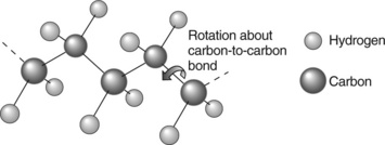
The weakest bonds of all occur between covalent molecules, as in gases, in liquids and solid materials, such as polymers. This is why hydrogen gas, for example, can only be liquefied at very low temperatures, where the thermal vibrations of molecules is low enough for the molecules to be held loosely together by the weak van der Waals bonds. One form of the bond occurs in polymers along the chain, and gives rise to rotational isomers. All chains can rotate about their carbon-carbon chain bonds (Fig. 1.7), and the resistance to rotation is determined by van der Waals interactions and steric hindrance (that is, the interference from the physical size of the atoms on the side parts of the chain). Thus polypropylene (PP) will have greater steric hindrance than polyethylene because the methyl extra side group (—CH3) is larger and thus interferes more than a simple hydrogen atom (—H). The resistance to rotation is therefore greater in PP than polyethylene or PE, giving it a much higher Tg, and also inhibiting crystallization. The different shapes of a single chain created by rotation about the chain links gives rise to different conformations, while the structure determined by the covalent bonds is termed the configuration. The configuration is necessarily a more permanent feature of a polymer since it is locked in at polymerization, while the conformation varies with temperature and environment.
But it is a truism to say that it is the weakest part of a structure that determines its stiffness and ultimate strength, so such bonds represent a force which cannot be ignored, and indeed, exert an influence in failure studies out of proportion to their significance in the spectrum of forces holding solids together.
1.2 Properties of polymers
As one might expect, the properties of materials are dominated by the type of bonding between the atoms and molecules. The strongest covalent bond occurs between carbon atoms, with diamond and graphite as exemplary solids for their extremely high melting temperatures, and mechanical properties such as stiffness and strength. Both exist in highly crystalline forms (Fig. 1.3), and are exploited commercially for those almost unique properties. Diamond crystals are used as a powerful abrasive on oil drilling tools, for example, and graphite for crucibles, and in another form, carbon fibre, as a very strong reinforcing agent in composite materials. But both are relatively expensive, so find limited application at present compared with the majority of materials. They can be thought of as representing the apex of the property pyramid, every other material falling below their maxima.
1.2.1 Polymers
The largest class of non-metallic material is represented by synthetic polymers, long chain molecules constructed from different repeat units (3–5). Their properties are determined not by their strongest bonds (the covalent bonds in the chains), but by their weakest, the van der Waals bonds between the chains. This is basically why they generally exhibit low melting and other thermal transitions compared with ceramics and glasses. On the other hand, relatively low transitions mean that they can be shaped easily, and indeed, shaped into very complex products with alacrity. Polymers can be partly crystalline, or amorphous, depending first on the regularity of the repeat unit. If it is symmetrical and regular then crystallization is possible, but may not always be achieved. Polyethylene is always partly crystalline because the repeat unit is very simple and symmetrical, and the melting point, Tm is an important characteristic of the polymer. There is another important distinction between two groups of polymers: the elastomers and plastics.
The thermal behaviour of all polymers can be described in the form of a so-called viscoelastic master curve (Fig. 1.8), where stiffness (tensile modulus, E) is plotted against temperature. The example chosen here is that for several different forms of polystyrene, the normal amorphous type, a cross-linked version and a crystalline type. At low temperatures, thermal motion of the chains is low, and the influence of van der Waals bonds high, so the polymer is stiff. As temperature rises, the chains become more mobile, so the chains can rotate and overcome the weak intramolecular bonds. This temperature is the glass transition temperature (Tg) and is another characteristic for a specific polymer. The polymer reaches a plateau, where it behaves like a rubber, showing reversible and long-range elasticity. Further increase in temperature causes viscous flow, although this region is inhibited by crystallinity or cross-linking. An amusing material which possesses all these attributes over a foreshortened time scale is ‘potty-putty’: it can easily be rolled into a ball, which when dropped bounces like a rubber. But when hit with a hammer, it shatters like a brittle glass. And if left unattended, it will flow like a liquid. It encapsulates all the viscoelastic states over a much smaller time frame than conventional polymers. Since crystallization and the transition to a rubbery state are controlled by the same inter-and intra-molecular bonds, one would expect a correlation between the melting and glass transition temperatures (Fig. 1.9). The relation is linear and Tg is roughly two-thirds of the melting point when the temperature is expressed in degrees absolute (Kelvin):


A list of thermal data for various polymers is shown in Table 1.2.
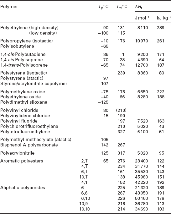
At yet higher temperatures (towards the right in Table 1.2), the notional polymer will degrade, usually involving chain break-up to smaller chains or fragments. Such degradation affects both viscosity and strength in just the same way, because the chain assembly is held together by chain entanglements, and when chain length falls below a critical value, the strength (and viscosity) fall catastrophically. The problem is directly related to the entanglement of the long chains with one another: above the threshold, they will tangle and so the chain assembly is held together by knots and loops between the chains. But below the threshold, there is no entanglement and the strength is very much lower and drops fast with falling molecular weight. Typical critical entanglement molecular weights vary in the following way:
| Polyethylene | 4000 |
| Polycarbonate | 4600 |
| Nylon 6 | 5200 |
| Polypropylene | 6700 |
| Natural rubber, PMMA, PEO | 10 000 |
| PTFE | 13 200 |
| Polysobutylene | 17 000 |
| Silicone rubber | 29 000 |
| Polystyrene | 356 000 |
Above these values, the strength is much greater and rises with molecular weight. At the other end of the scale of chain length, the strength is extremely high, but the polymer may be difficult to process into shaped components owing to the very high viscosity. However, the high strength is such an attractive property for many engineering products, that machining is used to shape components. Examples include ultra-high molecular weight polyethylene, PTFE and nylon, both of which are used as high-performance bearings, for example. The importance of cross-linking and crystallization in delaying the onset of creep and flow has led to new polymers such as thermoplastic elastomers (TPEs), which have most of the advantages of thermoplastics, but have networks stabilized against chain movement by physical cross-links in the form of domains or crystallites.
Control by the weakest intermolecular bonds means that stiffness and strength are also low relative to other materials, bearing in mind the large variation to which strength values are subject. Stiffness can also vary over wide limits, depending on fillers usually present in commercial materials. The values given for various mechanical properties in Table 1.3 are for unfilled, reasonably pure samples measured at a slow rate at ambient temperatures (ca 25°C). Increase in test rate almost always lowers strength because chain movement cannot respond quickly enough at high rates, a direct consequence of viscoelasticity.

High performance polymer fibres
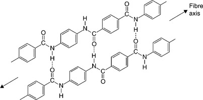
However, there are some important exceptions to relatively poor mechanical properties, especially where they can be made in a form where only the covalent bonds are strained (6,7). Such are the high performance fibres, such as aramid (Kevlar and Twaron) and UHMPE (Dyneema and Spectra). The structure of aramid is created essentially by binding the short linear chains in nylon into a so-called aromatic or benzene ring. Chain rotation is stopped and the hydrogen bonds between the chains hold the assembly into a very rigid and inflexible network (Fig. 1.10). Their mechanical properties are exceptional, and compare with carbon fibre as well as conventional materials (Table 1.4). They are used both alone in ballistic fabrics and for heavy duty applications such as ships hawsers and tendons, and also in composites with thermosets. They compare very well with high-strength metals such as steel, with high merit indices for stiffness (E/ρ and strength (σ/ρ), where E is the tensile modulus, σ the tensile strength and ρ the density. They are a measure of the stiffness and strength per unit weight, so are widely used for aerospace (body components and rotor blades, etc.) and other advanced transport vehicles, such as Formula Iracing cars.

Other uses
Polymers are also essential constituents of paints and many coatings, adhe-sives and foams. Paints are applied not just for aesthetic reasons but also to protect the underlying wood or metal from microbial attack and corrosion. They are normally filled with pigment, which lowers their strength, but may also form part of the protection of the underlying surface (especially of metals). But they also fail with time, being subjected to the same failure modes as bulk polymers, both physical and chemical (such as UV attack). Adhesives are a special class of polymer developed for binding two surfaces together, and similar comments apply. Foams are essentially composites of polymers with gas-filled voids, and are used as insulators, packaging and fillers for composite structures.
1.2.2 Natural materials
Synthetic polymers have many parallels in the natural world, and indeed, first exploitation of long chain materials started with natural substances such as amber (fossil tree resin), shellac (extract of beetle carapice), woods of all kinds, natural fibres such as flax, jute, cotton and ramie, and many other such derivatives. The first elastomers to be used by man comprised the dried latex from certain tree species (especially Hevea Brasiliensis), a material rapidly supplied by a bulk industry and known as natural rubber. It is still widely exploited, but now supplemented by a range of synthetic elastomers.
Exceptionally, natural rubber has a simple repeat unit (Fig. 1.1), in contrast to most natural materials. The ultimate in structural complexity occurs in proteins, where the sequence of units in the chains is unique and highly variable, so the concept of a repeat unit is redundant. It mirrors the complexity of its progenitors, DNA and RNA, where the sequence of base pairs is unique. There are numerous structural proteins, such as collagen and elastin, rigid and elastic proteins which help support our own bodies. However, they are rarely used as commercial materials nowadays. Silk is different, but an expensive protein for everyday use. A similar comment may be made about gossamer, the protein of spiders’ webs, which may find industrial application in the distant future if biotechnologists succeed in making it on a large scale. It will compete with the high-performance fibres, if it is ever commercialized.
Cellulose and derivatives have long been of structural use in many different forms. Wood derives its stiffness from cellulose fibres, and its strength as a composite from a lignin matrix. The fibres occur freely in cotton, flax, ramie and jute, among others. Rayon is a synthetic fibre made from native cellulose (5).
1.2.3 Properties of elastomers
The single most important development in rubber exploitation in a range of products came with Goodyear’s invention of vulcanization in 1848, where sulphur bonds are formed between chains to form cross-links (Fig. 1.2). They stabilize the ensemble of chains by preventing flow and creep, as shown by the viscoelastic master curve (Fig. 1.8), so rubber products will not deform permanently when loaded, a severe problem before Goodyear’s invention. Rubber boots could deform so badly in hot weather as to become totally useless, for example.
A blizzard of uses followed his intervention, including apparel (such as the waterproof Mackintosh), galoshes, bushes, bearings and anti-vibration mounts of all kinds, and ultimately, the rubber tyre. It came at a crucial time in the industrial revolution, providing protection for the many machines used in transport (especially steam locomotives) and with the internal combustion engine, the automotive. The tyre remains the single most intensive use of the natural material, and a host of synthetic elastomers such as neoprene, butyl and polybutadiene have also been developed, partly as a result of the shortage of natural supplies during the Second World War.
Lightly cross-linked elastomers are unique materials in that they experience large strains when loaded, sometimes up to seven or eight times their original length, as is common knowledge with the behaviour of elastic bands (8). The behaviour can be described by the equation:
where σ is the stress, G the shear modulus, E the tensile modulus and λ the elongation ratio (defined as the ratio of the new length to the original length). It is a non-linear stress-strain curve, quite unlike that shown by the initial linear behavior of Hookean solids (such as most metals). In addition, the modulus can be described in terms of the number of network chains, N, Boltzmann’s constant, k and the absolute temperature, T:
The equation predicts that the shear modulus increases with increased temperature, a surprising inference since the opposite is true for other materials. The effect is relatively small, however.
But the most important way of increasing the stiffness of rubber is by reinforcement with carbon black, a nano-particle material widely used as both a pigment and filler for many other polymers. It is essential for tyres where carbon black also toughens the elastomers used in their construction and provides a degree of protection against UV rays in sunlight.
Natural rubber (NR) is just one of a wide range of elastomers used in products today, and a typical car tyre comprises several different materials blended together. The tread has to grip the road, so energy absorption is important in maintaining a high coefficient of friction. It is usually a blend of NR and SBR (styrene-butadiene rubber), the latter being added to increase the hysteresis of the mixture. The tread is reinforced either by a steel or an aramid breaker in the conventional radial ply tyre. By contrast, the side wall must flex easily without heat build-up, so is a blend of NR and polybutadiene, a low hysteresis elastomer. The reinforcing plies are usually of rayon, a cellulosic fibre. The lining is of butyl rubber, a material resistant to diffusion of air through the wall. Many other rubbers are used in cars, with NBR, or nitrile-butadiene rubber, being used widely. The nitrile units are added in the copolymer to resist swelling when in contact with fuel, so it is used in fuel pipes as well as in uses where contact with fuel is likely (9–11).
1.3 Failure modes
The ways in which polymers fail include a wide variety of behaviour. However, it is convenient to follow what might be termed ‘conventional’ failure modes as observed in metals, since many will have encountered such problems during routine use of metal products. Many car owners, for example, will have been shown metal components by mechanics at their local garage which have fractured by fatigue, perhaps. Crankshafts and piston rods come to mind. They will also have seen rusted body parts, although the problem has diminished in recent years with the use of more corrosion-resistant metals and polymer composites.
1.3.1 Mechanical failure
Classical failure modes from application of load include the following distinct generic terms, normally easy to recognize if the loads and dimensions of a product are known at specific times in its life. Fracture is one of the most common failure modes, but can occur under different circumstances, such as:
• Overload: applied stress is greater than the strength of the product.
• Creep: distortion of a product under a constant load.
• Creep rupture: the end-point of creep with separation of the product.
• Stress relaxation: decay of stress at a constant strain.
Fracture is common in failed polymer products, and one which is usually obvious to the observer. There are some subtleties, however. For example, hairline cracks are very difficult to spot visually even on external product surfaces, and impossible if they occur on hidden parts of a product. They represent serious flaws from which complete growth to product separation can occur when low loads are applied to the product. Special methods of detecting such cracks have therefore been developed over the years, especially with metal products. An even more insidious problem lies with internal cracks which do not impinge at all on outer surfaces, especially in composite materials. Cracks are usually formed by brittle fracture, but may also be found with traces of ductility. A sure test for remnant ductility is to fit broken parts together, and see if an exact match is possible. If not, then some ductile deformation must be present. Thus broken ceramics are easy to fit together (at least, when the number of separate parts is small), but many broken plastic products are difficult to re-assemble due to remnant distortion.
There are many subdivisions of these processes known to metallurgists, which perhaps rings a note of confusion in the layperson. Thus ‘fretting’ is simply a type of wear caused by repeated movement of two surfaces against one another, so there are elements of a fatigue-like process occurring in this failure mode. Such is typical of all real failure modes, when different modes combine with one another to produce a failed product. So although each distinct mode may be easy to recognize when occurring alone, it becomes more difficult when in combination with others, which is really where the fun starts for investigators. Polymers are especially susceptible to creep, distortion and stress relaxation with time, a direct consequence of viscoelasticity (Fig. 1.8). However, such effects are inhibited by cross-linking and crystallization.
One symptom of product overload is crazing, when many small crack like features form within a plastic. Such crazes are often visible within transparent plastic products such as drinking beakers (Fig. 1.11), growing slowly with time, and changes in temperature and exposure to aggressive chemicals (such as during washing-up). They form during yielding of the material, and the internal space within a craze is foam-like (Fig. 1.12), with a lower density than the surrounding bulk solid. They are unique to polymers, and usually the precursors to true cracks (12,13).


Loading patterns
In addition, there may be several different ways in which the component is loaded, with the generic types including:
• Tension: pulling a product apart.
• Compression: crushing the product (opposite of tension).
• Bending: levering a body about a fulcrum.
• Shear: straining the part sideways.
The concepts are generic, and real loading patterns are usually much more complex, combining one or more of the elements together. Simple loading patterns are, however, easy to reproduce in a testing rig, so that much data is usually (but not always) available somewhere in the literature. And there are many examples of simple loading situations, such as a rope holding a heavy object (tension), a bridge column bearing the weight of a span (compression), a tree branch bearing its leaves (bending), bearing surfaces acting against one another (shear), and a rotating shaft from an engine (torsion). Bending is interesting because it produces compression on one side of the bent object (away from the point of load), and tension on the reverse side. Since most materials are weaker in tension than compression, failure usually occurs on the tension side of a bent object. However, there are always exceptions, such as the failure of a bent live branch, which fails by shear of the composite fibres of the wood, the cracks growing at right angles to the applied load. Dead wood usually fails by simple fracture on the tension side, owing to degradation of the composite structure.
Any of the loading elements can occur with most of the failure modes already mentioned, so that the rope might fail by tension overload or shear overload. Fatigue in compression is rare, however. In real cases, the loading situation is often indeterminate, especially for consumer products, which may be (and usually are) subjected to all of the above loading regimes at some time in their lives. If unknown, then that regime must then be inferred from the way the product has failed.
Load path
It is helpful in analyzing loading patterns to realize that forces must be connected in a chain through a product, so as to form a path. When there are several or many different components in that path, the load takes different forms along the path. Take a very simple example, one component pressing against a flat surface of another. The local load in the flat surface will be compressive, but will fall moving away from the point of contact until it reaches zero. Then there will be a compensating tension force in the surface to balance the compressive force. This is why tension cracks occur some distance away from the point of contact in say, a glass sheet impacted by a projectile. They form concentric rings of cracks. Damage to the material at the tip will also create radial cracks, so the final result of impact will be the characteristic cobweb pattern of brittle cracks found when a PVC pipe is broken by point loading (Fig. 1.13). The simple beam in bending is another simple example of how loading creates a combination of tension and compression across the thickness of the sample, together with a shear component for thick samples. The idea of load path through more complex configurations of many different components is helpful in elucidating how specific parts came to break rather than others, because it is the weakest component which governs the strength of the whole assembly.

Stress concentrations
One way in which the applied stress in a body is much greater than expected is the presence of stress concentrations. They are local variations in shape where the stress lines through the product are forced together (Fig. 1.14), and so magnified. Simple examples include:

Such design features are often inevitable in a product shape, but the magnitude of the stress concentration (Kt) can be minimized by fore thought. Compilations of stress concentration factors allow designers to do just this (14,15), but, life being what it is, they are often left unchanged in a new product, until a sudden application of load in service initiates a crack at the stress raiser. Corners are a common flaw in polymer products produced by the tool maker in the steel mould. They are reproduced exactly in the polymer shape, and remain to wreak havoc when the time is ripe (Fig. 1.15).
A simple formula for the stress at a notch tip is shown below. It relates the stress concentration, Kt to the length of the notch, D and the radius of curvature at the tip, r (Fig. 1.16):

So when r = D, Kt = 3, and Kt = 1 when the feature disappears. The formula shows that a round circular hole, and a semi-circular notch in the edge of a sheet triples the applied load. Other simple examples include a spherical void, which doubles the stress. Sharp cracks are much more serious, with the stress rising many times at the tip, and sharp inner corners have a similar deleterious effect on the strength of the product. Fatigue always starts at a design stress raiser, so their presence and position is a crucial factor in examining failed products. They usually determine the weakest part of a product from which cracks grow.
A surprising way in which stress concentrations can be exploited is so-called rubber toughened polymers. By introducing minute rubber particles into a thermoplastic, the strength can be raised greatly because each tiny particle acts as a spherical stress raiser. A crack is started at the edge of the rubber sphere, and since there are so many, the energy needed to break the material is very much greater than if they were absent. Typical examples include ABS, rubber toughened PVC and nylon.
It is a fallacy to say that stress raisers are always bad. For example, packaging should be strong enough to protect the contents, but weak enough to be broken when the product is needed. A small cut or notch is often provided for the user to initiate a crack or tear, suitably large enough to be visible, yet not obtrusive. Polypropylene is widely used for packaging as thermally sealed film, as bubble packs or large containers for meat and fish in supermarkets (gas filled to prolong product life). But designers frequently fail to provide a simple stress raiser to allow easy access to the contents, allowing the consumer to injure him or herself when opening it with a sharp knife (readily accessible in a kitchen where the product is to be cooked).
On the other hand, in products where non-metals are essential to protect the user from scalds or cuts, such as pan or knife handles, it is vital to eliminate the deleterious effects of stress raisers. A large carving knife for cutting a wedding cake suddenly failed, injuring the bride and ruining the special event (Fig. 1.17). The ceramic handle was poorly designed, with the tang of the blade exerting excessive leverage on the handle, the stress concentrated at the tang end. It is a classic example of an accident waiting to happen. Plastic-bodied knives should also be capable of brusque use without collapsing When furst used (fig.1.18)


1.3.2 Chemical Attack
If simple mechanical failure can become complex rather quickly, chemical attack of a product starts off being complex (16–19). That there are many ways in which materials are attacked is a reflection of the complex mixtures of chemicals to which they can be exposed in service, starting with the atmosphere around us. The problem becomes even more serious when the product is loaded, or possesses in-built forces which can be relieved by crack formation. Frozen-in strain is unique to long chain molecules, and is often produced during manufacture, when the chains are extended by flow of the melt in the steel tools. On cooling, the chains remain in an extended, but unstable state, ready to resume a coiled up conformation when triggered by external influences such as heat, load or certain chemicals. Perhaps the most common form of attack occurs through oxidation in its many different manifestations, although hydrolysis is also a major degradation mechanism for one class of polymers.
Oxidation
Oxygen (O2) in the air (ca 21% by volume) is the most active ingredient, but there are several other compounds which also degrade polymers (and metals as well). The composition of trace gases is variable, such as water vapour (measured by humidity), which changes depending on the prevailing weather and air temperature. Sulphur dioxide (SO2) is an aggressive pollutant (volcanoes, fuel burning) which oxidizes and combines with water to form sulphuric acid. Ozone (O3) is a more powerful oxidant than its parent, oxygen, and another product of pollution. It is produced by the action of sunlight on air contaminated with hydrocarbons (such as unburnt petrol), and photochemical smog is a serious problem in many cities in the world. The gas may only be present in parts per billion (ppb) but degrades many rubbers very quickly, and is extremely toxic to life. Chlorine (Cl2) is widely used as a cleaning agent or disinfectant for the same reason, and is also very aggressive to polymers. Oxidation in general must always be an expected agent of attack, simply because oxidizing agents are universally present around us. Another common household cleaning agent is bleach, which releases chlorine from a dilute solution of sodium hypochlorite. While useful in attacking and destroying germs, it will also degrade many thermoplastics.
Hydrolysis
Acid and alkaliwork against step-growth polymers by hydrolysis, that is, the chain is broken down by cleavage at the functional group linking the chains together. The functional group in nylon is the amide or peptide group (—CO—NH—), so the reaction in hydrolysis would be
Because the chains are halved in length at each step, the molecular weight drops rapidly, and once the entanglement threshold is reached, the material falls to pieces. As with ozone attack, the extent of reaction depends on the strength and concentration of acid or alkali, strong acids such as nitric, sulphuric and hydrochloric being more effective than weak acids. But there are some anomalies in comparing acid and alkali hydrolysis. Thus polycarbonate is unaffected by strong acids, but severely attacked by alkali. This is why it can be used for acid containment quite safely. On the other hand PET is not hydrolyzed by alkali, but is attacked by acids. Acids and alkalis are present in many common liquids, such as carbonated soft drinks (dilute phosphoric acid), cooking ingredients like vinegar (dilute acetic acid), baking soda and cleaners (sodium bicarbonate or carbonate).
Owing to its ubiquity, water can affect most polymers deleteriously. It can either act directly by hydrolyzing step polymers or in other ways. The problem shows up during processing or shaping, when high temperatures increase the chances of hydrolysis. Since most processing temperatures are greater than 100°C, any traces of liquid water in the feedstock will vaporise to form unwanted bubbles in the product. Most polymer feeds must therefore be dried thoroughly before moulding.
Ultraviolet radiation
A common cause of failure in many polymers occurs by exposure to UV radiation, commonly encountered in sunlight. The radiation occurs at wavelengths shorter than the blue end of the visible spectrum (hence the term, ultraviolet) and are of course invisible to the naked eye. The interactions with long chain molecules are complex, and beyond the scope of this book, but some general comments are possible. In the first case, UV encompasses a wide range of wavelengths, the shorter being most damaging (essentially because the energy of the radiation increases with shorter wavelength). Much of the most damaging radiation is, however, absorbed by the ozone layer in Earth’s upper atmosphere. But that still leaves sunlight with a substantial UV content. And it varies with climate, altitude and weather, so levels are rather unpredictable.
Theoretically, those polymers with double bonds or other absorbing functional groups are most at risk of UV degradation, but theory falls well behind practice because many commercial polymers, which have no absorbing groups, contain defects which do absorb. They may also have small amounts of co-monomers which are absorbing. Thus PE apparently has just simple CH2 repeat unit, but in practice, contains a small number of C = O or carbonyl groups produced by oxidation during high-temperature processing, so will eventually be attacked by UV. The effects of UV attack include cracking and the formation of a degraded layer on the surface, and pigments can also be bleached, in an effect known as ‘whitening’.
On the other hand, some polymers may contain groups which are non-absorbing but which are susceptible to UV attack. The best common example is polypropylene (PP), which has a tertiary hydrogen atom (H) present in every repeat unit:
It is less stable than the surrounding hydrogen atoms, and can be stripped off with less energy, and so represents a weak point in every unit. Because it is universally present, PP is very susceptible to UV attack. Figure 1.19, for example, shows the tops of two traction batteries degraded by UV, the white areas in the battery at left showing a particular problem of thermally welded polymer susceptible to radiative attack. Products which are exposed to sunlight should be protected from U V, and several fillers or additives are available for this purpose. They are absorbing compounds not dissimilar in function to sunscreens for skin, which is equally susceptible to UV damage.

1.3.3 Stress corrosion cracking
An important failure mode produced by chemical attack of polymers is stress corrosion cracking (SCC) by analogy with a similar problem encountered with metals (16–19). Trace amounts of powerful reagents can induce microcracks, which then grow slowly under applied loads or through another problem known as frozen-in strain. The classic example comes from the 1920s in India, when cartridges exploded in the rifles rather than firing a bullet. The cause was traced to hairline cracks in the brass cases, which in turn were caused by small amounts of ammonia gas emitted by dung heaps. It attacked the copper, forming a complex, so cracks were initiated where internal stresses (or residual stresses) were greatest. The solution was to anneal the brass after manufacture.
Similar problems occur in polymers, but the nature of chemical attack is different. As will be described in a case study later, a vehicle sprang a slow leak of diesel fuel, which went critical while on the road, causing multiple accidents to following cars. The leak had been caused by sulphuric acid attacking a nylon connector in the fuel pipe. Analysis of the remains showed that a small drop of acid had leaked from the battery above, initiated an SCC crack which grew slowly until sudden and total failure. The damage done to nylon fabrics such as tights and stockings by traces of acid is well known to users, and acid or alkalispills on most clothing of any composition will quickly cause irreparable damage. Many cleaning agents contain quite concentrated acid or alkali, and wise users will wear protective garments, such as polyethylene gloves or aprons. This polymer is immune to such attack since it is a chain-growth polymer. And it is not only polymers which are attacked.
Attack of many polymers by oxygen, ozone and chlorine are other forms of SCC in polymers, requiring a low stress or strain threshold for crack growth. Figure 1.20 shows the acetal junction on a water supply system under a laboratory sink, which failed suddenly and caused much damage to the computers in the department below. It had cracked at an early stage in its life, and grew slowly with time until it could no longer withstand the water pressure, and failed. The cause was traced to the low level of chlorine in the potable water supply, an unlikely possibility (it was thought at the time). However, other evidence was discovered from a trial in the USA which confirmed the problem.

1.3.4 Environmental stress cracking (ESC)
A further problem (not found in metals and alloys) encountered with polymers involves attack by organic fluids (16–19). There is no permanent chemical change, but the effects are the same as with SCC. Cracks are initiated and grow when product surfaces are exposed, and are only, and unfortunately, detected when the product falls in half, or leaks its contents. Just this happened when a pub landlord experienced a series of fractures of blow-moulded beer containers. As is usual with these examples, there is no obvious cause, and the problem remained a mystery until careful investigation exposed the truth. He had been cleaning the containers with a powerful detergent, and the detergent initiated microcracks in the walls, which then grew uncontrollable when loaded with beer. The manufacturer increased the molecular weight of the PE, and users were advised to change detergents, and the problem ceased. Detergents such as Igepal are in fact used in standard tests to check for ESC (environmental stress cracking) in products likely to be so exposed in service.
Step-growth polymers are also susceptible to ESC, especially non-crystalline or amorphous materials like polycarbonate. It is cracked by relatively low levels of active chemicals like methylene and ethylene chloride (which are also solvents for the polymer) and alcohols like methanol (CH3OH). Figure 1.21 shows a battery case used in a miner’s lamp which cracked and leaked when in use in the colliery. The cracks were caused by ESC induced by the solvent welding process used to assemble the viewing windows and lid. The solvent released chain orientation produced by injection moulding the parts. Transparent chain-growth polymers such as PMMA, polystyrene and SAN are also very sensitive to a wide range of organic fluids, threatening the integrity of structural uses, and visually unacceptable for simple products such as drinking beakers and decorative articles.

So what causes ESC under such apparently unusual circumstances? Organic polymers and organic fluids share common structures, carbon backbone chains and small carbon molecules respectively. They are frequently compatible, and the small molecules can usually diffuse into the long chain assemblies of polymeric materials. If the reagent is powerful enough, dissolution will occur, but if not, a thin layer of liquid will be present in exposed surfaces. The fluid swells the polymer and the surface layer expands. It is also weaker mechanically, so any applied stresses may initiate microcracks at vulnerable zones (typically at stress raisers such as corners, thread roots, and holes). Frozen-in strain (chain orientation) provides a driving force for crack growth, and must exceed a threshold value for growth to proceed (just like SCC). The growth rate will increase with stress and orientation levels, and may be intermittent for products used only occasionally. Thus fracture surfaces examined after product failure will frequently show lines where the crack has stopped, and then been reawakened by reapplication of stress.
1.4 Methods of investigating product failure
The way in which many different factors can affect the strength of a product clearly makes investigation of a specific failure difficult, unless the list of variables can be reduced or eliminated. That is just what is involved in systematic examination of failure: it is a process of elimination by careful collection of all the facts surrounding a particular incident.
1.4.1 Sifting the evidence
But what counts as evidence? The answer to that question depends on several, if not many, different kinds of facts associated with accidents, whether of metal or non-metal products (or composite products constructed of different materials). The following can be regarded as a minimum list. First is the testimony of any individuals who saw what happened before, during and after the accident. Then there are the circumstances surrounding the incident, such as the time and date, the environment, weather and so on. The technical records are an invaluable source of information and often available routinely for equipment failure (but not always). But the material evidence itself is probably the most important focus of enquiry, followed by the details of its history and provenance.
Witness evidence
If product failure has resulted in death, injury, or damage to property, statements from those in the vicinity will often be available. The earlier that statements have been gathered, the better. Memory fades, and the later a witness is asked to recall events, the greater the chances of error, especially if litigation has started. Bias creeps into statements and there is usually a lack of technical detail, because the interrogator is normally a lawyer with no technical expertise. If there are one or more victims, their memory may be affected by the accident. For example, falls from ladders are among the most common to occur to consumers, but falls from a height often cause mental shock, and amnesia about the events just prior to the fall. Often accidents occur so quickly that the witnesses or victims have great difficulty recalling the sequence of events, making the material remains the only mute evidence to the incident. Circumstantial evidence is frequently the only reliable evidence available, and the material evidence must be checked against any witness statements available.
Records
Documentary evidence is a vital source of the facts of a case, especially if equipment is monitored regularly and automatically. In industrial cases, documentation is often copious as a result of health and safety legislation, and includes:
With such a wealth of information available, the problem is one of sifting the records for the gems that will reveal how and why the incident occurred. For example, industrial processes are now usually automatically monitored by various sensors in the equipment. Variables, such as time, temperature, pressure and volume of contents, are measured and recorded remotely in computer databases. However, the data is usually indigestible until analyzed, and visualized in the form of graphs or diagrams. Trends can then be seen to help interpretation of the facts of the matter in hand. A great advantage of such data compilations is their objectivity, and bias is easily detected. Thus a faulty detector, such as a thermocouple, will show up when compared with other thermocouples in the system. A cross-check is available from calibration records. Systematic analysis will also expose whether or not the records are a fair representation of events. Sensors may be missing from critical parts of the system, although information can be inferred from the data supplied. Computer records are not infallible: computers crash, data can be lost or mangled, as any PC user knows to their cost, but they are generally an invaluable source of unbiased measurements.
Quality standards such as ISO 9000 require systematic record keeping of processes, materials and designs, and can give an insight into the past history of a particular product. Design-specific standards are a way of assessing compliance, but since they are drafted by committees composed of the manufacturers, they must be regarded cautiously. And in most cases, they are historic documents, and may not have been modified for the latest developments. Most contracts will specify compliance with one or more standards, so standards have an important status in the eyes of the courts.
Surviving remains
The material evidence which survives from a failure provides mute but revealing evidence of product history, often the key to unlocking the way it failed (16–19). It could be:
• the broken battery which exploded in the face of a mechanic
• the damaged bearing from a swing bridge
Such remains are normally preserved as the material evidence for further investigation, the proof positive of the cause of an accident and the justification of a case for compensation. But there are occasions when the broken product was formed as a result of the incident, rather than causing it. So the material evidence has to be seen in its context, and not in isolation. For example, a broken plastic ladder tip started an investigation to determine the cause of a ladder slip, when the user was severely injured by falling to the ground. But inspection of the accident scene showed that the tip broke after the ladder had started slipping down the wall, and could not therefore be taken as the cause of the accident. The trace evidence of its journey down the wall, scrape marks on the wall, was visible evidence of how the tip was broken.
Single items always prompt the question: was this broken part the only one to have suffered fracture? Sometimes, there are many similar broken products, suggesting faulty design, a rather more serious position for the product manufacturer, because rapid action must be taken to withdraw existing products in service and so prevent further incidents. The product must be redesigned to withstand service conditions, or alternatives provided which are capable of resisting the working environment. Thus many fractured or leaking miners lamps indicated one or more serious design flaws, and immediate action to provide alternative light sources to enable the colliery to keep working. Each broken product needs examination to provide a picture of the pattern of failure, and if a common failure mode is found, details of each individual failure are unnecessary. Statistical analysis of many failures can provide further clues about the design flaws causing those failures, helping the designer to improve the product. Design defects represent a serious challenge to the credibility of a manufacturer, and remedial costs can escalate rapidly. This is why it is so important to investigate early and ameliorate, or better, eliminate the escalation.
Every product failure demands individual treatment, and usually starts with simple visual examination, careful measurement of its dimensions and determination of its condition compared with an equivalent intact component. Comparison is a simple way of checking if the parts really are identical, and if not, the reason for divergence. Many products are now identifiable from logos, date stamps and manufacturing codes either printed or embossed on the product in a concealed position of the product outer surface. If the material is unknown, or degradation is suspected, it must be analyzed for the constituent parts: the matrix polymer, filler and any minor additives (such as UV absorbent). The analysis should aim to be non-destructive, but if necessary, sampling needs to be away from critical features such as fracture surfaces. Although direct comparison with unaffected product or component is ideal, it is not always possible. Visual inspection aims to identify the following product features as a minimum:
The search for key details does not stop at the fracture surface, however. Cracks which have not grown to completion are one objective of the search. Such sub-critical cracks provide evidence of the way the component has been loaded in service, and might show why failure has occurred in the first place. Thus discovery of sub-critical brittle cracks on a PP storage tank showed the tank to be under-designed for its function, and sub-critical cracks on the acetal plumbing fitting indicated that SCC was a failure mode to be brought into the picture (Fig. 1.20).
1.5 Public information sources
One way in which product failure can be studied is through the literature, and standard texts that are available, albeit of limited extent. There is a long tradition of publicizing the causes of failure, but usually only when that failure has been so severe in loss of life or property as to be classed as a disaster or catastrophe. Lesser failures have either become so common as to attract little attention (car accidents), or receive no publicity at all by being deliberately suppressed. That raises interesting questions about freedom of information, and prevention of further accidents of the same kind. The amount of information available on the world wide web is prodigious, but indigestible unless the searcher has a clear idea of the information needed.
1.5.1 Textbooks
There are several standard texts which are useful background for analyzing product failure, as discussed already. There is a shortage of case study compilations on polymers but some substantial works have been published in the last decade or so. Among them are the books by Ezrin (16), Wright (17) and Scheirs (18). A recent work discusses numerous case studies of both metal and polymer failures from a forensic viewpoint, including intellectual property (19). And several reviews also exist in the literature concerning design in polymers (20) and product failure (21) published in the series about polymer technology from RAPRA, an excellent and rewarding source of often obscure but vital source of further and detailed information.
1.5.2 Event reporting
It is likely that the vast majority of equipment failures not causing death, injury or great loss of property are not reported publicly. The company suffering such minor incidents will probably circulate employees details of the problems, and remedial measures taken, but the matter will end there. On the other hand, in some activities, both accidents and near-misses must be reported and publicized. The outstanding example is the aircraft industry, where legislation forces all incidents to be reported to inspection authorities, and remedial measures taken, all under public scrutiny. Near-misses of flying aircraft, for example, are widely publicized in the press. The railways, too, are obliged to report SPADs (signal passed at red), incidents which do not result in any accident but are an indicator of a potential problem. The problem became reality in the Ladbrook Grove crash of October 1999, when a local train passed a red signal and collided with a fast express, with great loss of life.
However, there is a growing body of literature publishing investigations into a wide range of product failures. The academic journal Engineering Failure Analysis (22) is devoted to publishing case studies of failed products, but it remains relatively isolated compared with strictly academic journals. Several volumes of papers taken from the journal are available (23). Although non-metallic failures are reported there, the majority involve metal products. Loss Prevention Bulletin (24) specializes in failures occurring in chemical plant, focusing on a wide variety of failure modes and their effects on the companies concerned. There is a long line of major disasters within living memory, which have created enormous damage to workers at the affected sites and further afield. Flixborough (1974), Bhopal (1984) and Buncefield (2005) are just a few of the disasters which will be remembered by the wider public. This and other accidents of chemical plant are discussed by Kletz (25). Civil engineers have a long and distinguished record of publicizing failures, reflecting the safety-critical nature of large structures such as bridges, dams, buildings and tunnels, for example. When failure occurs, it is likely to be dramatic and life-threatening.
1.5.3 Public domain
Among the foremost worldwide databases are those from Espace (26) and the US Patent Office (27). They itemize patents from the principle patenting countries, primarily the USA, Europe and Japan, and complete patents can be downloaded free. But why should patents be a source of information on failures? Inventors claim new products, which solve particular problems, and product failure represents an important part of those problems. So because glass is brittle and fails at rather low loads, laminated and annealed glass addresses the problem by toughening the material. Similarly, toughened plastics like ABS were developed to address the problem of brittle-ness in polystyrene. In addition, failure of new products can be studied simply by turning to the patent which establishes that product. Registered design databases such as that run by the UK Patent Office can also be a valuable source of pictures of a design at the date of registration. The UK trademark database is useful for determining ownership and identity of many commercial products. All such databases are readily accessible from the world wide web.
There are specialized databases for specific areas of failure, which are of great use in monitoring specific designs. Thus the FDA has a very large database of failures of medical devices at MEDWATCH, allowing an investigator to follow the failure history of specific hip joints, heart valves, stents and similar implants (28). Since there is usually a plethora of different designs, identification by tradename or trademark on the compilation gives the required information.
1.5.4 Materials and product standards
Unless products comply with specific standards, the ability to sell can be compromised in many markets. Compliance with product standards and regulations is now a major issue for many manufacturers. British Standards Institution (BSI) and the American Society for Testing and Materials (ASTM) have produced standards covering safety, performance and reliability of most products, including the influence of mechanical and environmental factors. In addition, each standard is reviewed and updated periodically, thus ensuring continued relevance. Equivalent standards exist in Europe (ISO), Germany (DIN), Japan (JIS), etc., and all are good reference sources (2,3). Within any standard, much of the required ‘background work’ is often included and could be of particular value in product liability disputes. A comparative analysis between a relevant standard, and the product or component in dispute may be needed. It should quickly become apparent whether the subject component did not conform to a standard.
However, standards may be of limited use. In many new products there may be no standard at all, or an old standard which has limited applicability. Standards are produced by a committee of testing experts and industry representatives, and the final draft is a compromise between conflicting interests. Thus there is no UK standard covering thermoplastic tanks, and the German standard DVS 2205 must be used as the only alternative. Many medical devices lack coherent standards because their development is growing fast, and the committees have not caught up with the latest products. So caution is required when looking for an appropriate standard. And who standardizes the standards? There is a range of styles even within an organization, some providing only minimal information, others more lengthy and even obscure.
There are ranges of standards covering test methods for polymers, and they are much quoted in data for specific polymers supplied by manufacturers. Unfortunately, the values quoted are usually ideal and the reality seldom meets that ideal, even for basic data like moduli. Part of the problem lies in the test samples chosen because they are pristine and clean, and never exhibit the problems of contamination found in real components. With tensile tests, moulded dumbbells are even more unrealistic. All technical data sheets should thus be regarded sceptically. The closer tests are to real conditions of exposure, the greater their credibility.
1.5.5 Disasters
Certain disasters from the recent past achieved a certain notoriety at the time, and such was their scale that public inquiries were established to investigate their causes. The numerous disasters on the railways come to mind, such as the Tay Bridge disaster of 1879 (29) and the lesser known but infamous fall of the Dee bridge at Chester in 1847 (30). Railway accidents have also recently been examined with specific reference to metal fatigue (31). Marine disasters were so common in the Victorian era as to be largely forgotten now, unless through an imaginative journalist’s pen, such as the mysterious abandonment of the Mary Celeste. But the tragedy of the sinking of the Titanic in 1912 was so enormous that it is remembered by every generation through a new film or book. Similarly, the destruction of the Hindenburg airship in 1937 seemed to presage or echo the widespread human misery suffered at the hands of the Nazis. Such disasters continue to fascinate the public, not least because of a degree of uncertainty about the precise causes.
While the Dee and Tay bridge disasters involved only metals (the cast iron girders and columns respectively), the Hindenburg (and the R101 airship of 1930) failed from the low strength and flammability of their gas containers and outer envelopes. They were composed of cotton fabrics reinforced with cellulose nitrate or acetate, and doped with rubber latex and other highly inflammable substances. Lightweight organic composites have been widely used in air and spacecraft for a number of years, and have been involved in a number of disasters, not least the Challenger and Columbia accidents. In the first disaster, in January 1986, the O-rings on one of the booster rockets failed, and the propellant exploded though the gap, engulfing the entire structure shortly after take off. The Viton rubber (a fluorinated copolymer) was very inflexible at the near freezing temperatures at lift-off, and could not seal the booster sections correctly. The problem was well known, but managers ignored the warnings. The second disaster, in October 2003, also involved damage during take off, and once again was recorded on cameras, just like the first disaster. The critical damage was caused by a large piece of foam insulation falling away as the rocket rose, and striking carbon-fibre composite on the wing. The damage fatally weakened the shuttle, but was missed at the time. When the craft attempted re-entry, the entire structure disintegrated. The accident exposed the testing regime at NASA to be flawed, because the problem was appreciated, but tests only conducted with very small pieces of foam, much smaller than that which actually flew off at launch.
The final demise of Concorde, the supersonic airliner, was signalled by an horrific accident at Paris in July, 2000. It occurred when a tyre blew out during take-off, and a large fragment penetrated the fuel tank above. The jet fuel was ignited by the engine nearby and the Air France plane eventually crashed, killing all on board. The small fleet was grounded, and after a short period when flights were resumed on the British versions, was scrapped entirely in 2003. Tyre blow-outs were not uncommon on other Concordes well before the Paris accident, although after the fatal crash, the cross ply tyres were replaced by a radial ply design, and the fuel tanks were reinforced by a rubber/aramid lining.
Non-metallic failure as a cause of major accidents and disasters is an unfortunate reflection of the lack of awareness of their limitations, and it is also unfortunate that the benefits of new materials are often overplayed and exaggerated when first introduced into the market. Engineers are then forced into the embarrassing position of explaining minor unanticipated failures, and being brought to account when lives are lost. The case studies discussed in subsequent chapters have been assembled largely from our own notebooks, supplemented by examples in the public domain. If failures of a similar type are to be prevented in the future, then publishing cases is a powerful way of educating designers and engineers of the shortfalls in the design and behaviour of polymers products.
1.6 References
(1) Lewis, P.R., Braithwaite, N., Reynolds, K., Weidmann, G.Walker P.W., ed. Chambers Materials Science and Technology Dictionary. Chambers, 1993.
(2) Walker P.W., ed. Chambers Dictionary of Science and Technology. Chambers, 2000.
(3) Billmeyer, F.W. Textbook of Polymer Science, 3rd edn. Wiley, 1984.
(4) Mills, N. Plastics: Microstructure and Engineering Applications, 2nd edn. Butterworths, 2005.
(5) Brydson, J. Plastics Materials, 7th edn. Butterworth, 1999.
(6) Lewis, P.R. High Performance Polymer Fibres. RAPRA Reviews. 9(11), 1999.
(7) Lewis, P.R., Highly oriented polymers in de WitDemaid and Onillon, ed. Case studies in manufacturing with advanced materials. 1992:97–122. [North Holland].
(8) Treloar, L.R.G. Physics of Rubber Elasticity, 3rd edn. Oxford reprint, 2005.
(9) Naunton, W.J.S. The Applied Science of Rubber, 1961. [Edward Arnold].
(10) Blow C.M., ed. Rubber Technology and Manufacture. Newnes-Butterworths, 1971.
(11) Morton M., ed. Rubber Technology. Van Nostrand-Rheinhold, 1973.
(12) Andrews, E.H.Fracture in Polymers. Oliver & Boyd, 1968.
(13) Hull, D.Fractography. Cambridge, 1999.
(14) Pilkey, W.D. Peterson’s Stress Concentration Factors, 2nd edn. New York: Wiley, 1997.
(15) Young, W.C. Roark’s Formulas for Stress and Strain, 6th edn. McGraw-Hill, 1989.
(16) Ezrin, M. Plastics Failure Guide: Cause and Prevention. Hanser, 1996.
(17) Wright, D.Failure of Plastics and Rubber products: Causes Effects and Case Studies involving Degradation. RAPRA, 2001.
(18) Scheirs, J.Compositional and Failure Analysis of Polymers: A Practical Approach. Wiley, 2000.
(19) Lewis, Peter Rhys, Reynolds, Ken, Gagg, ColinForensic Materials Engineering: Case Studies. CRC Press, 2003.
(20) Lewis, P.R. Designing with Plastics. RAPRA Reviews. 6(4), 1993.
(21) Lewis, P.R. Polymer Product Failure. RAPRA Reviews. 10(3), 2000.
(22) Jones D.R.H., ed. Engineering Failure Analysis. Elsevier, 1995.
(23) Jones, D.R.H., eds. Failure Case Studies, Volumes 1, 2 and 3. Elsevier, 2000.
(24) Donaldson, T, Loss Prevention Bulletin, IChemE, Rugby, England.
(25) Kletz, T. Learning from Accidents, 3rd edn. Gulf Professional Publishing, 2001.
(26) http://www.patent.gov.uk.
(27) http://www.uspto.gov.
(28) http://www.fda.gov/medwatch.
(29) Lewis, P.R., Reynolds, K. Forensic Engineering: a reappraisal of the Tay bridge disaster. Interdisciplinary Science Reviews. 2002; 27(4):287–298.
(29b) Peter, R. Lewis, Beautiful Railway Bridge of the Silvery Tay: Reinvestigating the Tay Bridge Disaster of 1879. Tempus, 2004.
(30) Lewis, P.R., Gagg, C. Aesthetics – v – Function: the fall of the Dee bridge 1847. Interdisciplinary Science Reviews. 2004; 29(2):171–191.
(30b) Lewis, P.R.Disaster on the Dee: Robert Stephenson’s Nemesis of 1847. Tempus Publishing, 2007.
(31) Lewis, Peter R., Nisbet, AlistairWheels to Disaster!: The Oxford train wreckof Christmas Eve, 1874. Tempus, 2008.