
Polymer storage tanks
4.1 Introduction
Thermoplastic and thermoset polymers have successfully displaced many traditional materials for two reasons: they are substantially lighter than competing materials like metals and glasses, but yet possess comparable if not greater strengths. In addition, they can be shaped easily at relatively low temperatures. It is well illustrated by containers, such as tanks and reservoirs.
Storage of very large quantities of fluids has traditionally been dominated by steel tanks, which are composed of steel sheets bent to shape and then welded together to form the final structure. The strength of a steel tank is determined by the strength of the weakest parts, usually the welds and holes in the structure needed for access pipes. Catastrophic failures have occurred of such tanks, and usually by fracture initiated at these locations, as the case of the Boston disaster illustrates. Other problems can arise from oily residues in tanks, which can form an explosive atmosphere.
But polymer storage tanks can also fail catastrophically, as the case studies in this chapter demonstrate. Such tanks are widely used industrially for holding liquids as various as fruit juice, pickling acids for steel makers and caustic soda for use in making cleaning agents for farmers. Some of these fluids are extremely corrosive and toxic, so special care is needed in designing tanks for storing them prior to use.
4.2 The Boston molasses disaster
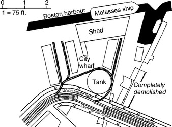
Perhaps the most notorious tank failure occurred in Boston at midday on 15 January 1919, when a storage tank suddenly broke after being filled to capacity with 2.3 million US gallons (8 700 000 litres) of liquid molasses. The wave of viscous fluid (consisting mainly of sugar in concentrated solution), killed 21 firemen and dockworkers in the vicinity. It demolished buildings nearby as well as part of the nearby overhead railway (Fig. 4.1). Little was left of the tank because numerous brittle cracks had grown across the structure, and it collapsed in pieces on the ground. In its original state it was 50 feet (15 metres) high and had a diameter of about 90 feet (27 metres) and was made from steel plates riveted together. The tank had been filled to capacity eight times in its two-year life since construction. The pattern of damage (Fig. 4.2) showed that the initial failure occurred on the landward side of the structure facing the buildings next to the overhead railway, which itself was also severely damaged. A train on the overhead railway had just passed the spot and was lucky to survive; the driver climbed down from his cab and had the presence of mind to stop an approaching train before it arrived at the collapsed viaduct (1). Rescue attempts to save the many individuals who had been engulfed by the sticky liquid went on for many hours, and as time went by, hopes of saving trapped victims inevitably faded. Firemen and police continued to work for many hours to retrieve the bodies. Many of the lucky but injured survivors numbering more than 50 recovered at the local hospital. An additional problem faced rescuers because the molasses was starting to harden, and workers found it increasingly difficult to wash away the viscous fluid to start the clear-up operation. Many people concluded from the state of devastation that the tank had exploded, such was the extent of destruction near the base of the tank where the tank seemed to have failed first. The accident left the city in a state of shock, and the rescue attempts lasted several days owing to the sheer amount of debris and devastation.

4.2.1 Causes of failure
The failure created much speculation as to the causes: sabotage using explosives and poor structural design being among the most frequently discussed possibilities. The tank owner, US Industrial Alcohol, was a proponent of the sabotage theory, but many independent commentators opted for structural defects. The evidence of the tank debris would be crucial to the investigation, and as much as possible was preserved for examination by the experts. There were many bomb attacks by Italian anarchists at the time, so sabotage could not be entirely dismissed. Although US Industrial Alcohol was not indicted on any criminal charge, a long civil action was started by the injured and relatives of the dead. The trial lasted three years and there appeared initially to be some support for the sabotage theory from explosives experts. However, their testimony was largely discredited. No one had been seen tampering with the tank beforehand, so an external bomb was unlikely. Dropping a bomb inside the tank was also very difficult, since there was a closed roof, and nobody had been seen on the roof at all preceding the collapse at about midday. Finally, if a bomb had been used, the shock wave would have smashed glass windows well away from the tank in surrounding buildings. No shattered windows were found away from the severely damaged structures close to the tank.
Further testimony from the Plaintiffs revealed many details of how the tank had been built two years before it failed. The wall thickness had been specified as 0.312 inches (8 mm) at the top increasing to 0.687 inches (17.5 mm) at the base to allow for the increasing hydrostatic pressure towards the bottom of the structure, just like a dam has to be much thicker at the base to resist the impounded water. But the steel delivered was thinner, varying from 0.667 inches (16.9 mm) at the base to 0.284 inches (7.2 mm) at the top. So the steel was about 3% thinner at the base and 10% thinner at the top, increasing the hoop stress in the walls over what would be expected.
Moreover, the tank had never been tested before use by filling with water to capacity – a normal test used to find any leaks in the riveted joints and assess any distortion on the side walls. It later turned out that the tank had indeed leaked the heavier molasses fluid copiously during its short life, and locals had collected it for their own use. At that time, molasses was used as a sugar substitute, and was also the main source of alcohol when fermented. Indeed, fermentation could occur during transport and storage and released carbon dioxide, which in an enclosed space resulted in high pressures building up within the space. The weather at the time of the failure was unusually warm, and it was suggested that extra pressure within the tank had occurred owing to premature fermentation.
Examination of the many steel fragments found on site showed that fracture first occurred at a circular manhole near the base of the tank and spread out from there upwards along the joints. One expert witness from MIT said that insufficient rivets had been used along the joints between the steel plates. He also observed that the hoop stress exerted on the walls at the base was 31 000 psi giving a safety factor of only 1.8. He would have expected a safety factor of 3 to 4.
The court found against the company US Industrial Alcohol and they paid out $300 000 compensation, equivalent to about $30 million today in one of the first ‘class actions’ brought in the state of Massachusetts. The tank was built below spec, was never tested correctly, and showed continual leakage from poor joints between the plates when used.
Fatigue from the joints is a possible failure mode caused by the repeated emptying and filling, and is a possible explanation of the Boston disaster because the tank failed after just eight complete fills from an inlet pipe near the base of the structure. It is likely that the crack, which grew uncontrollably, started where a joint met the edge of the inlet hole, so magnifying the inevitable stress concentration there. However, no such conclusion was reached by the court, so the final cause remains something of a mystery.
4.3 Failure of polypropylene storage tanks
The use of thermoplastic materials in large storage tanks has become common owing to their resistance to many chemicals which attack steel, while stainless steel is a very expensive alternative choice of material. They are simple to build, being composed of sheets of polypropylene thermally welded to make the final structure. Failures have occurred from a variety of causes, especially poor design and lack of adherence to the standards available (DVS 2205 in particular). The case study we published previously (2) covered the failure of a 30-tonne tank at Warrington on 23 August 1994, where it had been used to store a very corrosive fluid, 40% caustic soda. The fluid was destined to be diluted and added to a detergent solution used for cleaning dairy equipment on farms.
4.3.1 Catastrophic failure
The failure fortunately occurred on the night shift, so no one was injured, but there was substantial damage to equipment both in the factory and in adjacent premises from the caustic liquid. The manager was still there in an office overlooking the factory floor when he heard a ‘popping’ sound followed by the sound of ‘rain’, and when he turned round he saw a jet of fluid emerging from the tank above the so-called ‘bund’, a brick wall surrounding the tank to prevent such accidents. The tank had been filled that morning, so was full at the time, and this was only the fourth complete fill of the structure. Attempts were made to stop the flow by tapping off fluid but by the time it was achieved, a large volume had leaked away to cause property damage. The fire brigade were called to seal the area off and prevent the fluid entering local streams, where environmental damage would have been severe.
4.3.2 Investigation
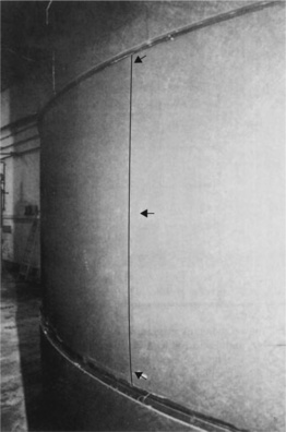
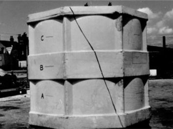
The tank comprised large panels of 12 mm thick polypropylene panels welded as shown in Fig. 4.3, with three horizontal buttresses encircling the inner cylinder. The failure had occurred in the centre part which lacked support from a buttress, and closer inspection showed that the panel was curved, the crack from which the jet had emerged lying at the centre of a weld (Fig. 4.4). The curvature can be seen on the plate if viewed side-on to magnify the effect. The fracture surface was seen directly, when the tank was cut up for analysis, and it showed a very simple sequence of events, with just four crack fronts. Since there had only been four fills from new, it was easy to see that each crack front represented the sequence of fills. The origin lay at a small pin-hole about 1.2 mm deep in the outer surface at the centre of the panel. The crack grew laterally rather than into the wall until the third fill, when it changed direction and grew into the thickness, finally reaching the inner surface directly beneath the origin (Fig. 4.5).


The curvature of the centre panel showed that the plastic had crept over time under load, suggesting that it had been under-designed. If that were so then other vertical seams along the same horizontal line should be similarly affected. Another set of similar but sub-critical cracks was found on an adjacent seam, confirming that the tank wall was probably too thin to resist the hydrostatic pressure of the contents. However, since a weld had shown a deep pin hole, the material was tested to see if it was within the strength claimed by the manufacturers. Tensile testing of several samples showed it to be within specification and reasonably strong for the intended purpose, with a tensile strength at yield of about 33 MNm− 2. The welds when tested proved to be slightly weaker than the bulk material, as one would expect, and there was some small variation, depending on the tiny defects present in particular samples. Their strength averaged about 21 MNm− 2, a value about 30% lower than the bulk material. The polymer was also examined using DSC and FTIR, nothing anomalous being found. The failure appeared to be a mystery then, because there was no material cause to explain the fracture. The design avenue of analysis proved more interesting.
4.3.3 Stress concentration
Since the depth of fluid was known, the hydrostatic pressure, P could be calculated, and from that a value for the hoop stress, oH in the wall at the origin of the failure. The pressure is given by the equation
where h is the height of the fluid above the origin, ρ is the density of the fluid (1500 kgm− 3) and g the acceleration due to gravity (9.81 gs− 2). So P is given by
where D is the diameter of the tank and t the wall thickness
So why had the crack grown if the hoop stress was only a small fraction of the strength of the weld of about 21 MNm− 2? The first effect must be the stress concentration effect of the pin hole, and should be about 21/3.4 or about 6. In other words the stress will have been concentrated at the base of the pin hole by about six times the nominal tensile hoop stress acting across the weld. And using a simple formula for stress concentration (3), it was possible to calculate the value knowing the dimensions of the defect (as measured from Fig. 4.5).
where (σ/σ0) is the stress concentration, D the depth of the defect from the free surface and r the radius of curvature at the inner tip of the defect. Figure 4.5 gives
The value for the stress concentration of about 9 is greater than that found experimentally, although another estimate using Peterson (4) gave a value of about 5. But there was another factor, and one only appreciated well after the event, when we inspected the welding process.
In order to make the final weld to form a cylindrical hoop, the welded flat panels were bent round and welded using a hot plate against which the two edges to be joined were held. Since the stress remained in the final structure, and was not relieved in any way, it lowered the strength of the tank considerably. Knowing the curvature of the tank, the extra stress imposed amounted to 1.8 MNm− 2. So the net result was a stress at the weld where the crack started of about 5.2 MNm− 2, much larger than was originally estimated. The net stress was now only about a quarter of the strength of the material, so a stress raiser of only 4 is needed for crack initiation, well below the independent estimates calculated above.
4.3.4 Cause of failure
It was thus clear that the tank had not been built correctly. It could not resist the steady increasing hydrostatic pressure from the heavy contents because there was an unprotected or weakened part in the centre of the structure. The single thickness of wall could not resist the pressure and started to creep under the steady load. A tiny pin hole in the vertical weld at the centre of the panel concentrated the stress locally to beyond the strength of the material and a crack started to grow from the bottom of the hole. And as the crack grew, the stress magnification grew too, so the crack grew faster at each fill of the tank. There came a point when the crack turned from growing laterally to growing inwards, and when it reached the inner surface, fluid started to jet out from the open crack.
An inspection of the relevant standard from the German Welding Institute or DVS (5) showed that the design deviated from the norms specified. The tank should have been built with a wall of steadily increasing thickness down the side, rather than by a series of hoop buttresses which left the centre of the tank unsupported. In short, it should have been built like a dam wall rather than like a barrel (Fig. 4.6). Comparison of the structure as built shows how far the design fell outside the DVS 2205 standard (Fig. 4.7).


Failure by creep rupture was inevitable. And detecting the problem before the final event would not have been easy since the crack as it grew would have been almost invisible in the dark corner of the factory where it was found. The sub-critical cracks were only found after the event by rubbing the weld surface with powdered chalk to give contrast. However, careful testing beforehand of such tanks should have shown there to be a problem. Although the density of water is lower than caustic soda, the centre section would have crept over time and been detected by simply measuring the circumference with a tape measure. As with the Boston tank, such an hydraulic test would have prevented the tank from failing and enabled the manufacturer to redesign the structure.
4.3.5 Other problems
The story might have ended there, with the insurers of the tank maker paying out the very substantial costs of the clean-up. But the same manufacturer, a small business, had built numerous other tanks to the same faulty design. All had to be inspected for sub-critical crack along central welds, and a number of small cracks were found. The tanks had to be reinforced or replaced given the danger they posed. For example, one location, a wire works in Staffordshire had two tanks next to one another, one holding an acidic liquid (ferric chloride solution), the other an alkaline fluid (caustic soda). If either had leaked, there was the chance of reaction producing heat and hence a fire could have broken out. However, neither had been filled to capacity since construction owing to restricted access to the site, so cracks were unlikely owing to the lower hoop stresses on the walls. Other tanks had been used to store relatively benign liquids such as fruit juice and soap solutions, but some of the tanks did show cracks and had to be reinforced given that had the tanks failed, even fruit juice can cause a great deal of damage if suddenly released. Fortunately, many were under-utilized and therefore unaffected.
4.3.6 Paint accident
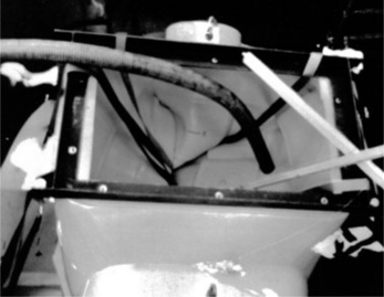
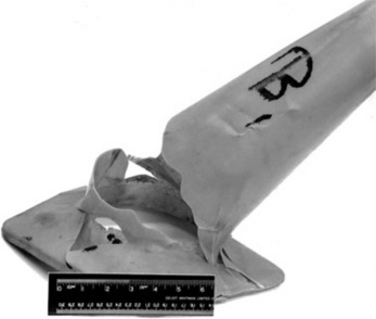
A different kind of problem arose when a thermoplastic paint storage tank suddenly failed just after installation at a paint factory. The bottom of the tank was raised from the base and inclined to aid release of the viscous contents (Fig. 4.8). The base was supported by four polypropylene panels, but they were clearly insufficient to support the load imposed by the contents, and the weld holding the base to the side wall gave way suddenly in an accident in 1998. It was the first time the tank had been used, and the resulting deluge of paint created a considerable mess on the factory floor. When the four panels collapsed, all the load of the contents was only supported by the weld with the wall. Although the strength of the weld was not examined directly, it was clear from its appearance that it was not a well-formed weld, judging by the extrusions of polymer surrounding the joint. Welds are in any case weaker than bulk material, and once a crack had started at any point, a single crack would grow very easily through the remainder.

The design had not built to the rigorous specifications of DVS 2205, which recommended a steel frame to support the inner bottom of the tank. This would have provided full support for the inclined base and paint without the fear of failure. Fortunately, only one tank was involved and the insurer met the costs of the clean-up and restitution of the storage tank to another design. As in the case of the caustic accident, the paint tank had been made by a very small company who were clearly unaware of the relevant German standard, or even basic design principles with polymeric materials.
4.3.7 Rotational moulded tanks
Another type of failure can occur in poorly designed underground storage tanks. They are widely used for sewage storage, water and fuel storage and so on. In the 1970s, one entrepreneurial company decided it would pioneer thermoplastic tanks for sewage storage using rotational moulding to create the structure in just one single manufacturing operation. The method involves placing powder polymer such as polyethylene into a steel tool, and rotating the tool within a large gas oven. As the powder was distributed evenly over the wall, it melted and formed the shape of the product. The movement of the oven needs care to ensure that an even wall thickness is produced, but this is not always achieved in practice. One positive advantage of the method is the virtual absence of residual stress or strain in the walls, a problem encountered in the Warrington failure. However, another problem may occur: premature oxidation. Because the temperatures are higher than used in normal injection moulding, the inner surface of the product exposed to the air in the free space may oxidize the inner surfaces.
In the present case, numerous very large tanks of capacity about 30 tonnes or 30 000 litres were designed (Figs 4.9, Figs 4.10, Figs 4.11) and installed at several different water treatment plants around the country by a pump manufacturer. After only a few months with their bases buried up to 10 metres below ground, several installations reported failure of the pumping equipment.


Inspection of the tanks showed that the walls had deformed inwards under hydrostatic pressure from groundwater, despite being protected by an external concrete shell (Fig. 4.12). The tank possessed a thick wall of polyethylene (HDPE) and was designed with buttresses, but still failed to resist modest hydrostatic pressures (given by equation 4.1 above). As might be expected, deformation was most serious with those tanks having a high external water table and no internal contents to balance the external loads. Tests of the design in a water tank showed that deformation of the walls was rapid (Fig. 4.13) and ended with the complete collapse of the tank (Fig. 4.14). Although the tank had thick 8 mm walls with horizontal and vertical buttresses, it could not resist the hydrostatic pressure, and it was unlikely that redesign could have improved the creep resistance. The manufacturer had to admit that the design was fundamentally flawed, and the pump maker resorted to a GRP design, which did have walls which were much more resistant to catastrophic creep.


4.3.8 UV degradation
The same rotational moulder also experienced a series of problems with failure of some of his other products, the largest of which were ‘mancabs’ for the shelter of workmen at the roadside (Fig. 4.15). Large brittle cracks were visible in the 8 mm thick walls (Fig. 4.16), but the cracks were most extensive on the roof of one of the cabs (Fig. 4.17), eliminating its function as a shelter. The seriousness of the roof cracks hinted at the cause, because roofs are inevitably exposed to greater exposure to sunshine, a potent source of ultraviolet radiation or UV. The inference was confirmed by sampling polymer on the roof and comparing the infra-red spectrum (Fig. 4.18a) with that of a bulk sample (Fig. 4.18b). Both exhibited carbonyl absorption just above about 6 microns (or about 1720 wavenumbers), the peak intensity being greater for the sample from the outer skin than that from the bulk polymer. The outer layers of polymer will be affected by UV degradation first, attack occurring at branch points in the polymer chains or carbonyl groups produced by contact with oxygen in the air when being shaped. Although relatively infrequent in HDPE, there can be enough to make the material sensitive to attack. The branch points where a side group or chain is attached possess a secondary carbon atom, which forms a free radical more easily than other carbon atoms in the polymer chain. At the high temperatures used in rotational moulding these are attacked first:


The chain is broken when the free radical reacts with oxygen in the air to form two aldehyde chain ends, which can then react further to form carboxylic acids:
The carbonyl group also absorbs UV radiation, so degradation starts at those points and rapidly progresses.
The carbonyl groups absorb infra-red radiation over a small range of wavelengths, and so can be detected in degraded polymer. Only a small number of chains are broken initially, but their effect on the tensile strength of the material appears very quickly in the form of brittle cracks. The strength of all polymers is exponentially dependent on molecular weight, so very few chain breaks can have a disproportionate effect on strength, a feature of other degradation mechanisms such as stress corrosion cracking (SCC). The inference was confirmed using GPC to compare the inner and outer surfaces of the hut (Fig. 4.19). The distribution has shifted to lower molecular weights as a result of UV attack.

4.19 GPC spectra of inner and outer surfaces of mancab showing chain degradation caused by UV attack.
The same manufacturer also made road cones, those devices used to guide motorists during the neverending works that afflict our roads, especially motorways. After only a few months’ exposure outside, rotationally moulded cones were found to be severely cracked (Fig. 4.20). The cone shown had probably been damaged by impact with a car, judging by the ductile deformation visible on the upper part of the device, but many brittle cracks were visible elsewhere. FTIR analysis confirmed the same diagnosis as before, with UV degradation the culprit. Another product which can suffer the same problem is plastic garden furniture, and some plastics are more sensitive than others to UV attack, especially polypropylene, which has secondary carbon atoms in every repeat unit, so the chances of reaction are very much higher:
The solution for polymers exposed externally to sunlight is to add a small amount of a UV absorbing additive, usually a small aromatic compound which absorbs the UV preferentially, dissipating the energy as low grade heat. Garden furniture and roadside furniture are both usually well protected nowadays, although other products can suffer the same problem caused by even occasional or intermittent exposure, such as the catheter examined in the previous chapter. But a cheaper alternative is to add say 1% carbon black, which has a similar protective effect by absorbing all radiation in the surface layers of the material, but the result is not always acceptable for consumer products.
4.3.9 Failed battery cases
Just the same problem occurred to a large battery manufacturer when their large traction batteries were fitted to fork lift tractors used by the Israeli Army during one of their many wars. The batteries were made by thermally welding blue dyed polypropylene lids to black PP cases. The tops were exposed to direct and bright sunlight in the Middle East, when the batteries were being recharged. They would normally be recharged at night but for some reason they decided on daytime charging, with the covers removed to expose the batteries. UV attack took place in the lids, being shown by fading of the lids at the welds (Fig. 4.21). The problem was confirmed by GPC (Fig. 4.22), where the molecular weight is plotted against the weight fraction of chains. As in the previous case, the whole distribution is shifted to lower molecular weights for the upper exposed part of the lid when compared with the underside. The critical entanglement molecular weight is also shown in the figure because this value represents the point where tensile strength drops steeply to a much lower value.


But why should the welded parts of the cases have been attacked preferentially? The answer came by a detailed examination of the welding procedure used at the factory. There was a faulty heating element on one of the welding machines, resulting in over-heating so that the weld material had already started to degrade, but this time by a thermal mechanism. When exposed to sunlight, the welds were preferentially attacked, resulting in brittle cracks developing around the rim. The fact that the blue dye was also attacked is another facet of UV degradation because many dyes and pigments are also affected by UV, fading with time of exposure. The problem is well known to art conservationists, who need to protect old works of art (especially watercolours) from the pernicious effects of sunlight. Textiles may be affected similarly, in a process known as ‘photo-tendering’.
The carbon black-filled cases remained unaffected because they were shielded form direct sunlight, although they have an intrinsic resistance to sunlight from their carbon black component, a well known UV absorber. The company not only calibrated their heating apparatus more regularly, but also added a UV additive to the blue lids to provide a more reliable product, even for use in unusual circumstances.
4.4 Failure of fibreglass storage tanks
The limitations of thermoplastic tanks alone can be circumvented by reinforcing the tank by an outer shell of composite material. In fact, composite tanks have been used for many years for a variety of applications, including septic tanks and storage facilities of all kinds. Several different types of composites have been used for the shell, the most common being glass fibre/ polyester and glass fibre/epoxy. However, there are also different ways in which the glass fibre itself is used. The cheapest option is to apply glass in the form of chopped strand mat (CSM), where each fibre is only about 2.5 cm long and exists in a random configuration in a so-called prepreg mat where the fibres are loosely held together by a binder. The strength of the material is not as high as filament wound composite where all the fibre present is continuous. On the other hand, filament winding requires special equipment and precise control, so is inevitably much more expensive. Other materials include woven cloth, intermediate in properties between CSM and filament wound products.
4.4.1 Chopped strand mat
CSM is commonly used to make boat and canoe hulls, for example, and in that form is applied by hand, using rollers to add the polyester resin which provides the matrix for the fibre mats. Layers are built up as each applied layer cures, and at a relatively slow rate because heat is given out during cure. If a succeeding layer is applied too quickly defects can occur within the material due to the heat build-up. Bubbles are a typical defect caused by the excessive temperatures produced. In the case of canoes, only two layers are needed, but boat hulls require many more, the precise number depending on the size of the boat. Up to 40 layers are used on minesweeper hulls, for example.
Since the fibres are randomly oriented in each layer, the material is equally stiff and strong in any direction in the plane of the layers, so it is not the ideal kind of reinforcement needed for tank shells. It is the hoop stress, the stress acting around the circumference, which is the greatest stress, being twice the longitudinal stress, which acts along the axis of the tank. This is why cracks tend to grow vertically in the sidewalls of gravity tanks, like the example of the Warrington tank examined earlier.
In making storage tanks, the liner is often made of polypropylene sheets welded together like the Warrington tank, and it then provides an ideal structure onto which the mats can be added one at a time. Allowances have to be made for the various inlet and outlet pipes, and often extra reinforcing layers are added here because they usually represent the weakest parts of the structure. Polypropylene is highly resistant to many chemicals, so makes an ideal lining. Other lining materials include uPVC, PVDF (polyvinylidene fluoride) and ECTFE, or ethylene and chlortrifluoroethylene colpolymer. They tend to have better high temperature and oxidative resistance than PP, but are much more expensive.
However, failures have occurred in such tanks, despite the existence of a long standing British Standard covering their design and construction (6) and considerable experience of composite tank usage, as the following case study describes.
4.4.2 Catastrophic failure on Teesside
The chemical industry in Britain has changed rapidly in the past decade as companies have changed hands, old plant is demolished and new plant is erected to satisfy new needs and products. One of the largest centres is Teesside, where, largely for historical reasons, many refineries and ancillary process plants have been built. The area is also a centre for the steel industry, stimulating companies like BOC (British Oxygen Company) to have production facilities to supply gases for iron and steel making. Such plant is designed to run automatically with little human intervention, mainly because key variables like temperature and pressure of specific processes are monitored continuously and controlled by computer. That means fewer staff employed on site, and fewer human checks that the equipment is running correctly.
But total chaos can result when a major piece of equipment suddenly fails. Just that happened in 2003, when a fibreglass tank used to store hot water from a ‘polishing’ unit collapsed, releasing 100 tonnes of near boiling water. Fortunately, there was no one around at the time to be injured, but the damage to other equipment next to the tank was severe. The cost of the damage was high, and since the process stopped, there were production losses to add to the total damages claimed from the insurers. The unit used a catalyst to make the product, and the hot water was produced by regenerating (or polishing) the catalyst at regular intervals. The water was alternately acidic and basic with neutralization occurring in the tank.
The first investigation was conducted by the The Welding Institute (TWI), a highly respected professional organization well skilled in such matters. Their report had been commissioned by the company who had built the plant, and the insurers wanted an independent report given the high cost of the damages claimed (in excess of £300 000). The builders were a large firm of contractors to the chemical industry, and the insurers of the tank constructors needed an independent report to ensure that all matters were investigated thoroughly and without prejudice. The initial report had pointed to a defective tank, but key information was missing, such as the conditions of operation and whether the builder of the tank had described those conditions of use fully to the men who built the tank, for example.
4.4.3 Plant damage
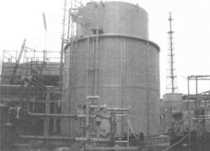
The original state of the storage facility is shown in Fig. 4.23, with access to the top via a steel ladder. The immediate aftermath of the failure was recorded as shown by Fig. 4.24, where the outer wall remains supported by a steel frame, and Fig. 4.25 which shows in detail the collapsed inner wall which originally supported the hot contents. The steel ladder at left in Fig. 4.24 shows the original height of the tank, now much lower owing to the removal of the centre of the structure. When examined some time later, the remains had been removed from site and dumped unceremoniously well away from the plant (Fig. 4.26). The picture shows the massive base plate upon which the structure had originally been erected, plus parts of the original side walls.


The structure of the tank is shown by the section in Fig. 4.27, a simple structure which has an additional part, a bund wall built integral with the tank itself. Figure 4.28 shows the surrounding equipment used for polishing and regenerating the catalyst. The outer wall is intended to prevent any leakage of the contents from reaching the outer environment. From the previous figures, it is clear that the bund wall had completely failed to achieve that particular objective. So had the walls of the tank itself been sufficient to retain the full contents of the tank under the conditions of use for many months since installation? The answer could only be found by sampling the base and side wall near the base joint and sectioning them to count the number of layers of CSM used by the builders. The walls are critical in resisting the internal pressure, especially at the base where the hydrostatic pressure is greatest.


4.4.4 Wall and base sections
The samples as collected are shown in Fig. 4.29, with Figs 4.30 and 4.31 showing the sections cut precisely at right angles to the base joint in the base and wall respectively. They show a uniform 6 mm thick inner lining plus a varying outer composite wall, within which several layers of CSM are visible. There is a problem with these sections, however. The base section is considerably thicker than the side wall, a situation which contradicts the need for a side wall to resist the hydrostatic pressure from the contents. The base of course will be supported by the concrete foundations on which the structure has been built, but the side walls have no external support, and must resist the hoop stress without failure.

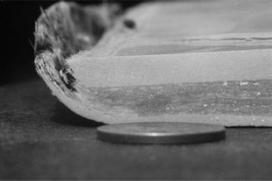
4.30 Section of tank base showing inner lining and composite bottom with diminishing wall thickness towards corner.

The sections show that the base was built with six CSM layers (each 1.5 mm thick), but they decreased to five at the corner; the diminishing thickness is especially visible in Fig. 4.30. But the side wall was only between 4 and 5 layers thick, or about 7 mm, thinner than specified (all layers had to be 6 layers thick according to the specification of this tank). The reason for the uncertainty lies in the so-called gel coat, which is the outermost layer made of a thin tissue of fibre mat. Taking that away gives an outer wall of only four layers, much thinner than specified. Both sections also showed many voids within the GRP layers (especially visible in Fig. 4.31), typical of a structure made by hand manufacture, where such defects are inevitable owing to incomplete penetration of the mat by viscous polyester applied during lay-up.
The final picture is an oblique photograph of the corner showing the way a brittle crack grew along it during the critical failure (Fig. 4.32). The detail is of interest because it shows traces of aluminium foil left over from testing of the thermoplastic liner for pin holes. The test is used with a spark gun and any through-thickness holes are revealed by the trace of the spark through to the conducting foil behind the sample. It should have been removed at the end of testing because its presence could weaken the joint.

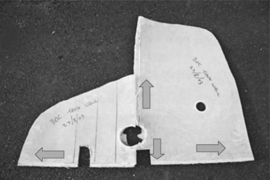
4.4.5 Reassembly of failed parts
The way the tank failed was explored by placing parts of the base, side wall and bund wall next to one another in a reconstruction of this crucial part of the tank where the failure started (Fig. 4.33). It was immediately apparent that the tank wall was severely distorted outwards, especially when the inner tank wall was compared with the flat and unaffected outer or bund wall. The distortion can only have been produced from the hot contents when the tank was full, and so exerting maximum hydrostatic pressure against the side walls.

The curvature was measured directly simply by using a straight edge laid against the inner side of the wall (Fig. 4.34). It showed a maximum bulging of 2.3 mm on the part of the wall shown in the picture. However, the pipe inlet was less affected, presumably because the junction resisted creep of the wall locally. The stress levels here will have been higher than elsewhere, and might help to explain how the failure occurred.

The creep of the walls showed that the tank wall was clearly under-designed for holding large quantities of water, the lowest part being most at risk from the hydrostatic pressure. The thin walls used here could only encourage creep since the hoop stress is higher than if a thicker wall had been used. However, the situation was rather more complex than appeared at first sight, especially when the history of tank usage was made available.
4.4.6 Fracture locus
One problem in investigating failures in composite materials is trying to map the fracture surfaces. By their very nature, crack growth in composites follows many different paths within the product, so there is no unambiguous fracture surface to examine and relate any features to the way the product cracked. But there are some details that allow reasonable inferences about the origin of a particular failure, and the way failure progressed. For example, the fact that a welded seam in the polypropylene liner runs into the hole and across, and failed along its length suggest that the critical crack started at or near the hole made for the pipe (Fig. 4.35). This makes sense because holes are stress concentrations by their very nature, increasing the local stress at the top and bottom edges by roughly a factor of 3.

The idea seemed to be confirmed by the local damage around the hole, because it is clear that delamination occurred between the liner and the outer GRP shell well before the final demise of the tank (Fig. 4.35). The separation extended some way into the side walls, up to about 10 cm in places. So this feature has added some complexity to the problem of explaining the failure, and one which needed further information for a detailed interpretation.
Nevertheless, reassembling the two separate parts shows the likely origin and crack paths from the pipe hole which caused the catastrophic rupture of the tank (Fig. 4.36). The smaller pipe outlet hole above the larger hole will have been exposed to smaller stress from the contents since it is higher from the base, and no seam passes though the hole.
4.4.7 History of usage
The tank involved in the Warrington failure had a simple usage history: four fills followed by creep rupture. But the GRP tank had been operating for much longer, and its history was rather more complicated. Since the plant was run automatically with computer control, there were voluminous records available which allowed the history of the tank to be reconstructed, with two sets of data being of greatest interest: the fill levels and the temperature (T). The data are plotted on Fig. 4.37, with the fill denoted by the axis at left and the temperature at right (measured on the outlet stream from the base of the tank).

The tank was built in early 2002, and was used to hold waste solutions from the polishing process in the first months of use. However, the temperature of the contents fell to ambient on five separate occasions during the first year of operation. Presumably the plant was being developed so was not working at full capacity. However, the tank never fell below 70% fill, so the wall was under high hydrostatic pressure from the very beginning. And it was at complete fill on four occasions, the last time just before the final failure in August 2003. After September 2002, the temperature lay between about 85 and 95 °C, and the contents were at 90 °C with a near full tank on the day of the failure.
The question that arises is whether or not the polymers were capable of resisting such temperatures while under high hydrostatic pressure. And the best way of answering that question was by using DSC to determine the thermal behaviour of the materials used in the walls.
4.4.8 Thermal properties of composite
The sections were sampled for liner and GRP from the base and side wall, and additional standards used for comparison. The liner samples were quite normal, showing a high melting point of about 165 °C, consistent with the standard sample of polypropylene (Fig. 4.38). Since the melting point lies well above the temperature of the contents, the lining will be able to resist the contents adequately with a good margin of safety.

The GRP samples were not crystalline at all, but exhibited a glass transition temperature or Tg lying at about 65 °C, somewhat lower than a standard GRP sample (Fig. 4.39). It effectively means that at about 70 °C, the material changes from behaving like a rigid plastic to a much more flexible elastomer. The tensile modulus of a rubber is about 3 MNm− 2, while that of a rigid plastic is about 3 GNm− 2, a difference of a factor of 1000. Although the GRP shell was reinforced with glass fibre (so the effect was ameliorated), it would have become considerably more flexible on exposure to the hot contents of the tank. In other words it will have deformed much more easily when stressed.

Here then lay a possible answer to the problem of creep deformation visible in the wall of the tank. The creep rate would have been much higher for an elastomeric solid than a rigid plastic shell, and it was likely that the poor temperature resistance of the shell led directly to the creep of the main wall. The problem will have been ameliorated to some degree by the glass reinforcement and by the temperature resistant lining.
4.5 Reconstructing the events leading to failure
The data thus showed that not only was the main wall too thin, but was also far too flexible at 95 °C to resist the hydrostatic pressures developed near the base when the tank was full or nearly full. The onset of failure probably starts with the early thermal cycling from ambient to temperatures above 95 °C, the last major excursion taking place in September 2002 (Fig. 4.37).
4.5.1 Thermal expansion
The effect can be estimated knowing the coefficients of expansion of the two materials, (aL) which are quite different (7):

The expansion in the tank circumference can be calculated for a rise in temperature (AT) of 70 °C assuming an estimated circumference of the tank of 13.2 m:
where ∆L is the change in length of a sample of original length L0:

So the polypropylene expands to a much greater extent than the GRP on heating the tank up. This will increase the effective hoop stress acting in the tank wall. On cooling down, the reverse process, the polypropylene will contract to a greater extent than the GRP shell, and it is here that delamination is the most serious danger because part of the stress produced by unequal contraction is at right angles to the wall thickness, so tending to pull the two materials apart.
The problem of differential thermal expansion is well known in other materials, and is exploited in bimetallic strips, which are used as simple switches in electric circuits. Thus an electric kettle uses such a switch to turn the kettle off when it boils, and so acts as a safety device which is responsive to rise in temperature.
4.5.2 Hoop stress
However, it is directly relevant to determine the hoop stress acting in the wall of the tank at the pipe junction (without the added thermal effect). Using equation (4.2) then the hoop stress is
where D is the diameter of the tank (4.2 m) and t the wall thickness. Assuming that the wall is intact, then the thickness near the base is about (6 + 7) or 13 mm thick by direct measurement (Fig. 4.31). The diameter of the tank is 4.2 metres (Fig. 4.27) and the pressure is given by equation (4.1), so
where h is the height of liquid above the pipe when the tank is full. The density is assumed to be 1000 kgm3, although will probably be slightly greater given that salts are formed from reactions between acids and alkalis from the polishing unit. Since the centre of the pipe is 15.5 cm above the base, then the height of liquid above is (6.5 - 0.155) or 6.345 m, so
The figure may be compared with the earlier estimate made on the Warrington tank of about 3.4 MNm2, the higher value being due to the greater height and head of liquid in the composite tank on Teesside.
The hoop stress acting on the two sides of the pipe hole will now be magnified by the effect of the hole by a factor of about 3, so the effective net stress acting at the hole will be about:
4.5.3 Strength of material
So how strong are the polymers used in the construction of the wall? In the Warrington failure, the strength of sheet polymer was about 33 MNm− 2, a value which fell to about 21 MNm− 2 across the weld. Although the strength of the chopped strand mat was not measured directly, there was some guidance from the literature, with Brydson (8) giving values in the range:
compared with a much higher value for woven cloth of
The variation presumably reflects the variability of quality achievable by hand application, such as the presence of more or less voids. But even at the lower value, the outer shell will have resisted the hoop stress of about 30 MNm2, unless other factors were at work.
4.5.4 Reactions in tank
Detailed records were available for the pH of the tank contents, and they showed many large differences in pH over the 2 year life of the tank, with differences of up to about 11. This implied that the contents had been highly acidic (lows of about pH1), or highly alkaline (highs of about pH12), with neutralization occurring in the tank itself and so producing yet more heat. The effluent tank had, in other words, been used as a chemical reactor and was not simply a storage container. The heat will have helped raise the temperature of the contents, as reflected by the temperature recordings from the effluent outfall.
4.5.5 Failure sequence
It was now possible to pull the various threads of this particular failure investigation into focus. The structure was under-designed for the task it was intended to perform, especially in the thinner wall, than either specified or needed to support the hot contents. Furthermore, the tank was defective in another way: the polyester matrix forming the outer composite shell was not resistant to high temperatures actually used in the tank up to 95 °C, not far off boiling.
The tank was used for about 19 months before finally failing, and it is likely that delamination started at its most vulnerable point at an outlet pipe near the base. Separation of the liner and composite shell occurred because the thermal expansion behaviour of the two polymers are quite different, and probably started at one of the last major cooling cycles in September 2002. A delamination crack formed around the pipe outlet and grew with time as smaller excursions in temperature and fill conditions occurred. When the void around the pipe was large enough, the polypropylene weld was exposed to very high loads, which can be estimated using the hoop stress formula, readjusted for a single thickness of 6 mm liner:
With a stress concentration factor at the edge of the hole, this effectively becomes an effective hoop stress of:
Such a value is in excess of the strength of about 21 MNm− 2, and as soon as the hoop stress reached this level, weld failure was inevitable. It may, for example, have been triggered by the small cooling phase in mid-August 2003 (Fig. 4.37). The crack once started will have grown vertically in the weld, so splitting the tank into two parts (Fig. 4.36). However, the lower crack hit the lower joint between the base and the sides, and the crack ran circumferentially as well, reducing the structure to a total wreck. It is worth noting that the PP liner was probably welded in the same way as the Warrington tank, judging by the way the failed liner was seen to be flat rather than curved after the accident (Fig. 4.33). That implies that there was an inherent residual stress present in the formed liner, increasing the likelihood of failure, as already discussed above concerning the failure of the Warrington tank.
A wave of hot water hit the thin bund wall, which immediately failed, so releasing the contents of the tank into the local environment (Fig. 4.25). The tank had been inspected only 3 hours before the final event by an operator, who luckily was absent at the time of failure. He reported that the bund space was dry at that time of his last inspection. The original investigator suggested that the tank had experienced about 30-40 cycles of filling, but few were complete fill-empty cycles where the change in loading conditions is most severe. He thought that fatigue might be occurring at the pipe joint, but even detailed examination of the failed plastic weld failed to show any evidence for fatigue of the kind clearly shown by the Warrington tank.
He also performed some analyses on the GRP wall material, calculating the glass content by burning away the polyester. The GRP showed a lower glass content than expected of about 25%, rather than the 30% recommended by the British Standard 4994. So the composite strength probably lay at the lower end of the expected strength range mentioned above.
4.5.6 The bund
That the overall design of the tank was also flawed is shown by the behaviour of the bund. It was a very thin composite wall of only 6 mm total thickness and there was no way it could withstand an impact from the nearly full contents of the tank. It was doubly flawed because it concealed the state of the inner tank wall. It completely enclosed the lower part of the inner wall (Fig. 4.27), so any distortion would not have been visible for inspection (access was by a small door at the top). If an independent bund well separated from the tank had been used, the distortion might have been seen, and so the accident averted. The use of an integral bund violates the basic concept of a bund, that is, to prevent the tank contents reaching the environment should a leak of any kind occur. It might be feasible to contain a small leak, but a massive failure would be impossible to contain safely. It would have been far better to have incorporated the bund wall into the main structure to add the extra reinforcement needed for supporting the contents. At the same time, an independent separate bund wall of the conventional kind should have been constructed.
4.6 Dealing with the aftermath
During the investigation a number of aspects of the case were exposed. They included statements by the management of the company that installed the tank and equipment (they had sub-contracted the tank itself to another company) that suggested that they thought the tank had been specified to resist water at 105 °C. The drawing on which the tank was based, actually stated 90 °C as the working temperature. Unless the tank had been pressurized, it would have been an impossibility since water boils at 100 °C. Needless to say, the material would have been even less likely to have resisted the higher temperatures, and failure would probably have occurred even faster than it did.
The same contractors produced a marketing brochure before the accident (and picked up in their offices after the incident), which stated that ‘The new hydrogen plant … [on north Teesside] … broke several records. It’s the largest in England, the fastest ever built (in an amazing 19 months) and was completed ahead of schedule, on budget with no lost time incidents.’ Tank failure after completion of the plant seems to illustrate just why safety and structural integrity may sometimes be sacrificed for speed and cost. But fibreglass storage facilities can be built safely, provided that close consideration is given to the appropriate standards and codes of practice.
4.6.1 Standards
BS 4994 is a relatively old standard dating from 1989, and is very comprehensive in its recommendations (6). One important aspect of the standard is the classification of storage tanks into three categories, classes I, II and III. The highest category class I tank needs independent verification and extensive tests on the materials of use, as well as calculations of the strength, weld and bond points, ash tests to determine glass content; with all rigorously documented with records of the tests including hydrostatic tests with water. The classification depends on the:
• nature of the contents (toxic, corrosive or flammable)
The highest category (I) is automatic for toxic, corrosive or flammable contents, so on that criterion alone, the tank should have been treated as class I. The liner is known to be compatible with the contents, but the design temperature of 95 °C is well above the recommended limit of a heat distortion temperature of 60 °C for the tank walls. The heat distortion temperature is closely related to Tg, and in this case a value of 62 °C was quoted by literature used by the tank builders. In fact the standard recommends a value of 42 °C as the maximum temperature which could be used safely for this polymer grade. The design pressure was static head only, but the standard recommends that any tank sizes above 50 m3 must be a class I tank (it had in fact a capacity of 100 m3). The only other criterion of note is the safety of the tank. Since failure could have killed or injured any bystander, then it had to be a class I storage vessel.
The specification of the tank stated quite wrongly that it was a category III tank, but on several independent criteria it should clearly have been a class I vessel, with all the checks needed by the standard. It was not even known whether a simple hydrostatic test had been performed before the bund was added, or even after it had been added. Like the Warrington and Boston tanks, such a simple test of filling it with water might have prevented catastrophic failure. It would certainly have caused visible creep of the sidewall if left for a short time.
4.6.2 Acid storage tanks
GRP tanks are widely used for storage of other hazardous fluids, such as hydrochloric acid. A small tank farm at Immingham dock is shown in Fig. 4.40, where the acid is stored prior to shipment. The acid is used for secondary oil recovery in North Sea oil and gas fields where it is pumped down oil and gas wells. The tanks are all GRP and the largest stand about 20 metres high. The entire set of tanks is protected by a solid bund. They are made from either woven mat or filament wound GRP, and well reinforced at the172 Forensic polymer engineering base (Fig. 4.41). The extra layers of reinforcement can be seen clearly in the lower parts of the structures; the pile of chalk present has been used to absorb small leaks of acid caused by seal breakdown. The tank farm is shown because a problem arose of alleged degradation of ABS plastic pipework in the pumping arrangements used in the complex, and is discussed in a later chapter. So composite structures are safe to use when built with high-strength materials to the best standard. However, other problems can arise in tanks that have been built to standard and with sound materials.


4.6.3 Other failures
A number of other failures of composite tanks have been reported in the literature, and show that other failure modes can occur in storage tanks. A very large GRP tank used to store dairy products collapsed suddenly 10 years after installation, when a crack near the base grew from an internal defect. The tidal wave of liquid demolished an electricity sub-station and two men standing nearby just managed to avoid serious injury. The structure was made from dual layer laminate, with a polypropylene liner and CSM shell, although the shell comprised many more layers than the failed Teesside tank. The tank was filled and emptied daily with about 20 000 gallons of liquid, and was also cleaned daily with a hot caustic solution at 77 °C. It was also occasionally cleaned with nitric acid. Inspection showed that small cracks grew in the welds of the liner, and they were mended, presumably using a hot torch.
The origin was traced to a region in the wall at the base, where milk product had seeped through a small hole or crack in the weld into the shell. The weld had been repaired at some time in the past, but was obviously unsuccessful. The investigation (9) ascribed the failure to stress corrosion cracking (SCC) of the polyester matrix of the shell possibly by acid attack with crack growth encouraged by the daily stressing of the base from the product fill. However, the author failed to publish good images of the fracture surfaces and analysis of the loads on the structure, especially photographs of the fracture. Hydrolysis of the polyester might be one route to SCC, but the contents were also exposed daily to caustic solution at a high temperature, so there is a possibility that hydrolysis may have occurred by that mechanism. In addition, there was the chance of attack of the glass fibres of the shell.
4.6.4 Glass fibre attack
The degradation of the glass fibre reinforcement is cited by several authors as another mechanism which can cause tank failure (10). A necessary corollary of those theories is that the liner must have leaked acid contents before such attack, so implying a faulty liner. Ezrin describes the fracture of a 3.7 m diameter and 6.2 m high GRP tank where a single brittle crack started at a circular manhole near the base, not dissimilar to that described here. The tank was under-designed and it failed three years after installation. The E-glass fibre used was also sensitive to acid attack from the dilute sulphuric acid contents, and SCC was suspected.
4.7 Setting new standards
A survey commissioned by the Health and Safety Executive (HSE) in 2003 reported several other failures of dual laminate and other polymer storage tanks (11). Although they concentrated initially on helix-wound HDPE tanks used to store HF, they extended the review to include many other materials, and the very wide range of hazardous chemicals and fluids stored in those structures. After discussing the various design procedures recommended by existing standards, they pointed out the importance of allowing for cyclical loading (not allowed for by the standards), a point already raised by the two case studies of the Warrington and Teesside tanks. Cyclical loading must be expected for most storage tanks and fatigue cracks will always start at the weakest points in the structure, especially at welds and joints. They also emphasized the potential role of radiative heating by the sun for external tanks. The authors pointed out the importance of hydrostatic testing before use, as required by most standards, and added some interesting details, such as adding detergent so as to lower the surface tension and allow the contents to penetrate cracks or other defects more easily. It is also important to use water at a temperature applicable in use, a test which would probably have prevented the Teesside accident if conducted over a reasonable time scale of several days to allow for equilibration of the wall. Inspection for hairline cracks is important for all loaded structures, but another test they recommend is measurement of the circumference for any signs of creep: the test is simple and easy to perform, with a reliable guide to creep of the walls.
The different kinds of defect produced by faulty welding is clearly a widespread problem, and they emphasize the importance of automatic methods. However, the inherent stress produced by bending sheets to form the final joint is not mentioned by the authors of the review.
They go on to describe the types of problem experienced in storage ranks and discuss the collapse of a GRP horizontal tank which had been under-designed by a manufacturer who had no previous experience of tank building, a problem which ranks with those discussed in this chapter. Failures of HDPE tanks used for storing very strong acids such as nitric acid and hydrofluoric acid (HF) are described, as well as others where cracking has been induced by the acid itself. Nitric acid is especially pernicious because it also a strong oxidizing agent. Examples of brittle cracking are shown in detail.
Foundations are important for providing a stable base, concrete being the best option. Sand foundations may be unsuitable and can shift with time, placing the tank under severe stress. Bund design can be a problem, one example being of a GRP tank which floated after waste water was accidentally allowed to flow into the bund, putting the pipe joints at risk. But they do not mention the problem of integral bunds, a strange omission given the problems which can follow, such as hiding the main wall, as occurred at Teesside. But if open to the atmosphere, then the accumulation of rainwater must be prevented.
They discuss the use of DVS 2205 and BS 4994 in design, some of the problems of which would be addressed by a forthcoming standard (12). The review is an excellent summary of the problems of thermoplastic tanks, and ways to prevent future failures.
4.8 References
[1] Puleo, Stephen, Tide, Dark. The Great Boston Molasses Flood of 1919. Boston: Beacon Press; 2003.
[2] Lewis, P.R., Gagg, C., Reynolds, K.Forensic Materials Engineering, Case studies. CRC Press, 2004.
[3] Lewis, P.R., Reynolds, K., Weidmann, G., Braithwaite, N.Walker P., ed. Chambers Dictionary of Materials Technology. Chambers, 1995.
[4] Peterson, R.E. Stress Concentration Factors, 1974. [also in Pilkey (op cit), chart 4.50 (1997)., Figure 128, page 195].
[5] German Welding Institute (DVS) 2205. Standard for thermoplastic tanks, 1992.
[6] British Standards Institute. Specification for vessels and tanks in reinforced plastics, 1987. [BS 4994].
[7] Open University, Data Book, Table of thermal properties of polymers. Design and Manufacture with Polymers. 1999. [T838].
[8] Brydson, J., Plastics Materials, Butterworth, 7th edn, 1999.
[9] Hull, D., Fractography, Cambridge University Press, 2002.
[10] Ezrin, M., Plastics Failure Guide: Cause and Prevention, Hanser, 1996.
[11] Stonehill, J., Bainbridge, H., Heyes, P.F., Health and Safety Labs (HSL), HSL/2006/21. Specification and Inspection of Thermoplastic Storage Tanks. 2002 Available on the web at http://www.hse.gov
[12] BS-EN BS EN 13121-3:2008 GRP tanks and vessels for use above ground. Design and workmanship; British-Adopted European Standard; 2008. [/ 236 pages, / 29-Aug-].