
Polymeric medical devices
3.1 Introduction
If one were to examine areas of great advance in the use of new materials, medical devices would surely be among the first to be noticed. One reason why polymers are now so widely used is their similarity to the natural materials from which our bodies are built. They have similar mechanical properties, and so are flexible in response to body stresses. Some polymers are inert and unreactive to body fluids, and can all be designed into products of some complexity with great ease. The body environment is highly reactive since it is in a continual state of producing energy for body functions (such as muscle movement), with many complex chemical pathways in both the fluids (such as blood) and tissues (such as muscle and bone). Enzymes, or biochemical catalysts, target specific molecules in changing their structure, whether degrading them to simpler units, or changing their make-up. But there are some relatively simple environments where the body breaks up the molecular constituents of food into much simpler units, and uses a strongly acidic environment to achieve that end. Thus starch is effectively degraded to glucose monomer units by acidic hydrolysis in the stomach, the glucose then becoming a vital energy source for muscles. Implants must be able to resist such attack in other aggressive environments in the body, temporary implants like catheters for short periods, and permanent implants like hip joints for many years. On the other hand, degradation can be exploited in the case of sutures for stitching wounds, where the stitches disappear over a timescale matching the healing process.
In general, many common polymers show good biocompatability, but care is needed to ensure their high purity owing to the problem of leaching of possibly toxic additives which are usually added to commercial plastics to lengthen their lifetime. Additives like anti-oxidants cannot be used for fear that they will contaminate the body. That then raises problems of enhanced sensitivity to degradation, especially thermal degradation during moulding, for example. UV absorbing additives present the same problem of leaching, toxicity and the chance of degradation before use. As if those problems were not difficult enough in themselves, there is another problem: sterilization. All devices to be used within the body must be totally sterile, so that no bacterial or viral contamination of the patient is possible. Equipment feed lines to patients must likewise be sterile, especially in the inner surfaces which make contact with fluids such as serum, blood, infusions of drugs or liquid nutrition. So how is it achieved? There are several processes currently in use: heat, ethylene oxide gas and gamma radiation. Each represents a different way of killing bacteria or viruses lurking on products, but exposure times and dose rates must be judged carefully to eliminate any possibility of affecting the polymer or polymers involved. Heat sterilization, for example, must be matched to the thermal behaviour of the polymer, not exceeding the Tg, and never the melting point of the material. Ethylene oxide is less aggressive, but cannot be used with polymers where there is any possibility of chemical reaction with the repeat unit. Gamma radiation is a highly energetic form of radiation, which can initiate degradation in sensitive chain molecules. Experiments prior to supplying new devices will normally show what doses are effective only against extraneous bacterial contamination. Whatever form of sterilization is used, must be prevented or eliminated with devices for medical use. It implies ‘clean room’ conditions of manufacture, with well-sealed moulding shops, positive pressure of the internal (filtered) atmosphere to prevent ingress of dust, and a very high level of cleanliness. The feedstock polymer is usually a specific grade developed for a particular product, with traces of metal catalysts (or any other remnants of polymerization which might be harmful) removed for the potential leaching risk. The moulding conditions must be chosen so as not to expose the hot melt to excessive temperatures when degradation starts to occur. And such traces might be difficult if not impossible to see by eye alone, remaining hidden unless special checks are made of product quality.
Most regulatory bodies, such as the FDA (Federal Drugs Administration) in the USA and the MHRA (Medicines and Healthcare Products Regulatory Agency) in Britain, will insist on a programme of tests to ensure that a new product or device will not prove damaging to patients. The testing will usually include toxicity tests, integrity tests (such as for mechanical strength under expected loading conditions in the body) and in vivo tests as a final check on compatibility with the body. This might include tests using animals, the first balloon catheters being tested in this way, for example. For testing must be rigorous and demanding so as to assure the integrity of the final product. In reality, it does not always happen, as some of the following cases show very clearly. And there is always the chance of unexpected damage, not caught by the rigorous quality testing demanded of medical products.
3.2 Failed catheter
Catheters are such a common item in hospital practice that they are usually taken for granted by all who use them. They are the plumbing tubes for infusing patients with drugs in intensive care, but if they break, damage to the patient can follow, or worse. They are easy to manufacture by extrusion, where hot molten polymer is pushed by a screw through a narrow circular die. The bore is created by an internal cylinder (or torpedo) within the die so that the difference between them forms the wall of the tube. Catheters of varying stiffness can be formed by varying wall thickness, but also by varying the material of construction.
3.2.1 Thermoplastic elastomers
Thermoplastic elastomers (TPEs) are a relatively new class of polymer that offer a wide range of modulus because their microstructure can be controlled during polymerization. They are often block copolymers, made by reacting two or more different monomers together in such a way as to provide two or more different types of chain within the same molecule. Because different polymers are usually incompatible with one another, so-called domains are formed of one of the polymers. In the first of its type to be made in the 1960s, SBS (Styrene-botadiene) copolymers form regular arrays of domain, which can be globular if styrene is the minor constituent (Fig. 3.1). Such domains act as a kind of physical cross-link because they anchor the flexible and elastomeric polybutadiene chains, the physical properties being much superior to polybutadiene alone. Creep is much reduced, so that shaped products retain their integrity. The stiffness of the material is similar to that of PB alone, but if the styrene content is increased, the modulus increases in step (1). A different type of TPE is made from polyester and polyglycol (polyether) chains (2). The stiffness is in general greater than the elastomeric part alone at high polyester content, thanks to the presence of crystalline domains (Fig. 3.2) rather then amorphous globules, as is the case with SBS materials. Other TPEs, which have all the advantages of thermoplastics, but a greater range of stiffness, include many varieties of polyolefin, such as ethylene propylene copolymers, where physical cross-linking is achieved by crystallization of small stereoregular block of one or the other component (1). And there are also block copo-lymers of nylon and rubbery segments. Such a commercial material is Pebax (made by Elf Atochem), trade name for a range of nylon TPEs. Like the polyester TPEs, they offer advantages for catheters owing to the great range of wall stiffness, giving doctors greater manipulative control of IV (intravenous) and catheters designed for insertion into the body.


3.2.2 Accident at childbirth
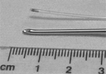
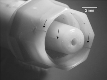
One application found for Pebax was in catheters for infusing an epidural anaesthetic into pregnant women during labour. The anaesthetic may be requested to ease the lower abdomen pain when giving birth. So how is it administered? The thin (1 mm outer diameter) catheter of length one metre, is sealed at one end, and three tiny holes created by a hot wire in the adjacent side for transmitting the drug directly into the spinal fluid of the patient (Fig. 3.3). The so-called distal end of the catheter is threaded through a hollow steel needle (a so-called Tuohy needle) which punctures the spine (Fig. 3.4). It emerges into the fluid core of the backbone, and the drug can then be drip-fed safely into the patient. After birth, the Tuohy needle is withdrawn, carrying the catheter with it.

But a problem occurred in 1990 when a Mrs K was giving birth to her first child (6). Following safe delivery of the baby boy, the needle was withdrawn but the catheter tip found to be absent. Inspection of the remaining catheter showed that the tip had broken away across the proximal infusion hole, and remained in the patient’s spinal fluid. Any operation to extract the small piece of plastic was out of the question, because surgical intervention might cause greater damage than justified. The tip was sterile and apparently presented no further risk to Mrs K. However, she thought otherwise, and brought an action against the hospital, and the makers of the catheter. In preparing expert reports, the failed catheter was clearly key evidence for the case, one way or the other. When first examined, the long length of remaining catheter proved to have been held in storage pinned to black card, and the proximal end through which the epidural fed showed signs of brittleness. Nurses remembered having problems attaching the proximal end to the drip, and had to tape the parts together. There were brittle cracks present here, and at several other places along its length. In addition, there appeared to be a slight yellowish tinge to the failed catheter.
The expert acting for Mrs K examined the failed end of this length in a solicitor’s office with a hand lens, not an ideal way of assessing the evidence. He thought he could see traces of score marks running across the failed end, perhaps created by the catheter being withdrawn over the sharp end of the Tuohy needle. This should not have happened, because there are strict guidelines given to hospital staff that the Tuohy needle should be taken out first, and then the catheter withdrawn through the needle. In his opinion, the staff had been negligent by withdrawing the catheter first, and so damaging the end.
3.2.3 ESEM of the failed end
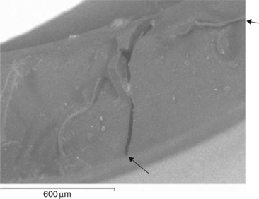
The dispute entered a new phase when experts were appointed to act for the hospital and manufacturer. A joint meeting agreed that high resolution microscopy of the fractured catheter could help resolve the main issues, whether to confirm or negate the score marks claimed by the claimant’s expert. In one of the first uses of ESEM, the distal catheter end is shown in Fig. 3.5. Although covered with dust from the solicitor’s office, there appeared to be no trace of the score marks claimed by the claimant’s expert. Another new catheter had been damaged by withdrawal through the Tuohy needle, and its surface (Fig. 3.6) was quite different to the failed sample. It does show score marks from tiny defects in the sharp edge of the needle blade, and cut debris at the edge. So how had the catheter actually failed? Another part of the proximal end was also examined, and its failure surface examined using conventional SEM (made conducting by a thin gold film). It exhibited a brittle glassy fracture over most of its end surface, and a longitudinal crack, confirming what the nurses had said. Most interesting however, was the presence of a ductile tear of very similar type to that shown in the failed tip (Fig. 3.7).


Our interpretation of the features shown by the distal end (Fig. 3.8) indicated that the part had fractured in a mainly brittle, but also partly ductile way. There were two large flat zones next to the infusion hole with a thinned and torn part at the furthest extremity of the surface. There was no trace of the cut marks at all. Far from indicting the hospital staff, the evidence at both the distal and proximal ends showed a brittle catheter. Such a device should remain tough and ductile in response to loads, so how could it have become brittle?

3.2.4 Material and mechanical testing
There was now some basis for tests to check the material quality of the pure polymer. It would be a multifold attack, first tensile testing of the remaining length of catheter, and second by infra-red spectroscopy near the brittle part of the tubing. Density tests showed little difference between the new and failed catheters, while DSC showed a single melting point at about 170 °C in both samples, consistent with a separate and intact polyamide phase. However, there was a large difference in the heat of fusion (ΔHf) a measure of the degree of crystallinity, as measured by the area under each peak of the new and failed catheters (Fig. 3.9). The upper curve of a new catheter showed a much smaller melting peak than that of the failed catheter, and the melting points were slightly different:

| Standard new catheter | Tm = 184°C, ΔHf = 33Jg− 1 |
| Failed catheter | Tm = 171°C, ΔHf = 45Jg− 1 |
The results were confirmed independently by the other experts, but what do they indicate? One possibility is that polyether chains degraded in length, so fewer nylon blocks were held by polyether chains, and so free to crystallize, increasing the heat of fusion. The small drop might indicate a loss of nylon block chain length too, because polymer melting points decrease with decreasing chain length.
The length of catheter provided several samples for straining to failure in simple tension, the results showing the catheter to be much weaker than a new catheter tube. Samples from the proximal end were too brittle to withstand bending around the grips of the tensometer, but the distal end samples were tested successfully. The results on two such lengths of catheter were as follows:
| Mean tensile strength | = 8 Newtons |
| Mean extension to break | = 15% |
These results could be compared with five results obtained on new catheter:
| Mean tensile strength | = 28.2 Newtons |
| Mean extension to break | = 650% |
So the new polymer exhibited a tensile strength well over three times the strength of the failed catheter, with no evidence of yield at all in any of the samples tested.
Conventional infra-red spectroscopy yielded very little, with the spectra from both new and failed samples being effectively identical, a common result for polymers which may be in the early stages of degradation. However, the expert for the manufacturer chose a new method to analyze a very small piece from the failed catheter. It was FTIR microscopy, a technique which had just been developed by an instrument maker. It involves passing an infra-red microbeam on a chosen area of the sample in an optical microscope. The spectrum shown in Fig. 3.10 compared with a new sample of catheter. Although the spectra look similar, there are in fact subtle but significant differences, as noted by the arrows. Slight shoulders on bigger peaks indicate traces of compounds not present in new polymer, and their position pointed towards low molecular weight esters produced by photo-oxidation (possibly UV attack), as suggested by an independent survey carried out by French workers in the 1980s (3). Although the FTIR experiment was carried out by the expert acting for the manufacturer, the tensile tests were carried out in the presence of all the experts, so could not be disputed later when the case went to trial. Some NMR spectra were obtained on catheter material, indicating that the polymer comprised poly-glycol and polyamide 12 chains of structure:


The melting point of about 170 °C was consistent with the commercial brochure technical data supplied by Atochem (4). However, it was surprising that a wholly aliphatic polymer should be sensitive to UV degradation, simply because the only chromophore in the repeat unit is the carbonyl group in the peptide bond (—CO—NH—). On the other hand, the French workers found that photo-oxidation did occur, mainly within the polyether parts of the molecule. Alternatively, or in addition, the polymer may have been exposed to excessively high temperatures during moulding. Hydrolysis was less likely, since the nylon blocks appeared unaffected in the failed catheter. Although GPC would have revealed the extent of chain breakdown, results were not obtained in time before the dispute was resolved.
3.2.5 Degradation theory
The sum total of all the tests (DSC, tensile and FTIR) now pointed to chain degradation of the catheter, but at what stage? There was no evidence that it had been carelessly exposed at the hospital to direct sunlight, and in any case, ordinary window glass screens out the most harmful part of the UV spectrum in sunlight. It was more likely that degradation had started earlier in its history. More information emerged from the manufacturer, enabling a flow diagram of the probable sequence of events in its life to be constructed (Fig. 3.11). There was no evidence that any other catheters made from the two batches, FLA 234 and 235, had degraded in a similar way. Moreover, quality tests at several stages had not detected any problem, so how could it have happened? The fact that the brittle areas were isolated even on the one metre length of the failed tubing produced one possible explanation. It was this: extruded tube would have been stored in coils, and it is possible that the failed catheter was made from a length of tubing on the outside of the coil, where it might have been exposed to direct sunlight. Perhaps it occurred just after extrusion or at some stage in transport. A brief exposure to sunlight might have been enough to start the degradation in a small way, but then accelerated by gamma sterilization at a further stage in its manufacture (Fig. 3.11). No anti-oxidant or UV absorber would have been used owing to the problem of leaching, so leaving the polymer unprotected. High moulding temperatures could also have enhanced the onset of UV degradation. An alternative possibility could involve ESC or SCC, but no data was available on the fluids which are known to crack the material. It is assumed that the manufacturer would have tested the polymer against known medical fluids to check its resistance, but there was always a chance that a new fluid cracking agent contacted the catheter after its removal from its protective packaging just before use.

3.2.6 Conclusions
The action proceeded towards a trial in the High Court, although all the evidence showed that a manufacturing defect was the most likely cause of the accident:
![]() The nurses discovered the proximal end to be brittle after it had been inserted.
The nurses discovered the proximal end to be brittle after it had been inserted.
![]() DSC showed a big increase in heat of fusion, and a lowered Tm compared with a new catheter.
DSC showed a big increase in heat of fusion, and a lowered Tm compared with a new catheter.
There was still substantial disagreement between the experts, despite a meeting held between them. However, some new evidence emerged after the meeting, and just before the trial was due to commence. There was an unexplained feature of the damage to the catheter tip. What load could have caused the fracture to have occurred? After all, there should be no load at all if the catheter is enclosed by a hollow steel needle, and the end is simply resting in the spinal fluid. The answer came from a sample of a used catheter from a recent successful birth by epidural. The tip was intact, but was distorted at the tip: the consultant reported that it had been compressed by the adjacent vertebrae, and been deformed by the compressive load (Fig. 3.3). There was no sign of brittle cracking. This fact helped resolve the dispute, and the case was settled just before the trial was scheduled to start. The claimant received damages from the manufacturer, and the hospital was exonerated. The brittleness at the proximal end had only been discovered after the tip had been inserted into the spinal fluid, and the birth could not be suspended until a new catheter had been fitted.
A literature search failed to find any other reported examples of Pebax catheters failing by brittle cracking, but informal evidence for cracking of other catheters came during the 2001 ANTEC conference in the USA, when a short paper of this case study was read in the Failures Analysis and Prevention section (5). One delegate mentioned that he had had a similar intermittent problem with HDPE catheter tubing, also probably caused by UV exposure. Great care in manufacture of medical grade polymers for catheters is clearly needed.
3.3 Failure of connectors
Intravenous (IV) catheter lines find extensive use in intensive care, and for drip feeds to many other groups of patients (the elderly, chronically sick and premature babies, for example). It is natural, then, that systems have been developed for allowing different drugs to be fed through the same tube, for other fluids to be supplied, such as serum and TPN (total parental nutrition, a synthetic equivalent of milk). Multiple supply implies use of junctions (Y-junctions, for example), connections and ways of supplying drugs via hypodermic needle. There are many such medical plumbing systems available to medical staff in hospitals, and indeed for self-medication to chronically ill, but stable patients, who have been transferred home. Many systems were developed in the 1980s and 1990s, and are still being actively developed further. Different materials have been used for the catheters of such systems, including silicone rubber, for example. It is a very stable polymer, is stable to relatively high temperatures and inert to most body and medical fluids. It is normally supplied as cross-linked tubing for extra dimensional stability. The catheter ends are supplied with connectors to enable infusion of drugs via hypodermic needle, which typically comprise a rubber seal embedded in a plastic connector. The needle can be pushed through the seal and retracted, the rubber relaxing back and so apparently providing a secure way of delivering a measured dose with no extraneous contamination.
3.3.1 Connector failures
However, there have been problems with the quality of the thermoplastic fittings. The connectors at the ends of the catheter are often injection moulded from polycarbonate, and in some cases have shown brittle cracks. Such cracks are difficult for medical staff to spot in time, and can lead to bacterial contamination of the fluid supply to the patient. The problem was highlighted by investigators in the early 1990s when large numbers of such devices first started to appear on the market (7). Splits in hubs were often encountered, especially in connections known as luers (from the first user of such devices), where a smooth conical end is pushed into a female socket. The problem is the hoop stress applied by the pushing action, tending to initiate cracks from defects on the edge of the joint or elsewhere (such as poorly formed gates, the point where plastic has been injected in the tool of the moulding machine). In addition, any variation in fitment dimensions will put extra hoop stresses on the female socket.
Another device uses a screw fitting, where the male part is twisted into the female luer. However, there are several problems with this fitting, too. Such fittings are covered by an ISO standard (8), but there still appear to be problems of fitment. There are two problems. One is that screw fittings are insecure unless some means of locking the fitting can be made. The problem is well known to motor engineers, and various devices have been developed to stop the joint unscrewing. The second problem is the fit between connectors from different suppliers. Owing to small dimensional differences, the joint can unscrew quite readily, so making the composite joint unsafe.
3.3.2 Premature cracking of connectors
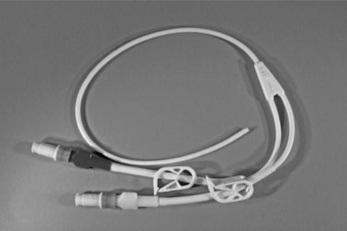
The problem of premature cracking of connectors became critical when one design was introduced into the British market in the mid-1990s (9). The connectors are designed to join lengths of catheter, and are typically used in Hickman lines, which are usually made in silicone rubber (Fig. 3.12). Each device is made by welding two parts of the outer casing together to form the final shape (Fig. 3.13). The device is 25 mm long and 10 mm at its widest point. The case conceals an inner working mechanism, which consists of a stainless steel helical spring behind a latex rubber seal. The stainless steel tube within the spring runs along the centre line of the design and provides the pathway for the liquids used in the IV line (Fig. 3.14). The rubber seal has a re-sealable cut at its centre to allow luers to be inserted easily for a new line. Such a female luer also has an external screw thread for secure attachment of the connection. The other end of the device consists of a male luer which can be connected to the main line, and is also fitted with a screw thread.


The device was tested to standards current in the early 1990s (8), and appeared to fulfil all requirements. The device offered a sealed unit so as to prevent contamination of the central feed line by pathogenic bacteria. The problem of infection in hospitals is well known, and hospital authorities have been tackling it by a variety of routes including cleaning and disinfection of working surfaces, improved staff hygiene and so on. IV lines need extra special care since the lines offer direct entry to the body to pathogens, bypassing the normal defences of the body. Lines carrying nutritional fluids such as TPN (total parental nutrition), a synthetic liquid equivalent to milk, are especially at risk since they offer nutrition to bacteria as well as the patient.
That the design was faulty emerged later (9), during a court action brought by the mother of a premature baby born in a hospital in the southwest of England in 1995. The premature baby was fed intravenously via a Hickman line, but suffered infections in the early part of 1996 when the new connectors started to be used by that particular hospital. According to nurses, doctors and the mother herself, the connectors kept cracking, and would last no longer than a day. Sometimes brittle cracking was so bad that they had to be replaced even more frequently. On one occasion, when the baby was being transferred between hospitals by ambulance, the Hickman line snapped and was retained by the mother after surgical removal (Fig. 3.12). It was to play a central role in the subsequent proceedings. Both of the green polycarbonate shrouds on the connectors exhibited brittle cracks (Fig. 3.13). In June 1996, the baby contracted meningitis while cracked connectors were still in use, and almost died. It later was found that the little boy had suffered brain damage which medical experts assigned to the near fatal episode in June 1996. The mother then started proceedings in 2002, accusing the hospital of negligence in using such devices, and the manufacturer for supplying faulty products.
The surviving samples retained by the mother were examined using macrophotography but were not subjected at that stage to the more revealing methods of optical or electron optical microscopy. The solicitor in charge of the case was very protective of the samples, and it later transpired that they were the only surviving examples of many similar failed connectors. The low magnification survey showed that brittle cracks were present at the gate of the green shroud, where molten polymer was injected during manufacture. The cracks were entirely brittle and extended over large parts of the outer shroud. No examination was made of the inner parts of the devices, since it would involve dissembly of the joint, involving extra stress on the samples.
Brittle cracks tend to occur at the gate because this is where frozen-in strain or chain orientation is greatest, a common problem with many polymers and where polycarbonate is especially susceptible if moulded incorrectly. Early work with mining products had shown that polycarbonate battery cases cracked in a similar way when exposed to organic solvents (methylene and ethylene chloride) used during solvent welding the product (see Fig. 1.2 and Chapter 4). It was concluded at an early stage in the investigation that the connectors had been poorly moulded, although their birefringence could not be measured directly since they had been filled with pigment.
3.3.3 Disclosure
Several years later, in 2006, the case advanced with the claimant asking for disclosure of design, manufacture, testing and failure documents from the defendants. The failure reports from UK hospitals made interesting reading. There were records from first introduction of the device in 1994, of numerous and sometimes distressing complaints from many different hospitals of the problem of cracked connectors, and the MDA (Medical Devices Agency, precursor to the MHRA) was asked to investigate. However, the problem was not tackled until many months later by the company. The first failure reports made by internal workers at the manufacturer were unimpressive:
![]() reports lacked a systematic approach with only two photographs given in evidence
reports lacked a systematic approach with only two photographs given in evidence
The extensive literature on polycarbonate seems to have been ignored. So as a direct result, no serious action was taken to either withdraw the faulty products from supply to hospitals, or to re-examine the design and manufacture of the connectors. Even when a new design using different polymer was introduced in early 1996, the older designs continued to be used by hospitals, including that where the premature baby was being treated.
3.3.4 Literature
In fact, there had been many warnings published in the technical press about the problems of using polycarbonate in luers and connectors of the type made in France and the subject of the investigation, and they were published before the French design was launched. Particular warnings were expressed in papers presented to the Failure Analysis Group of the SPE (Society of Plastics Engineers) at their annual ANTEC conferences. Stubstad was one of the first researchers to warn of the problems of premature cracking of polycarbonate luers in a paper at ANTEC 1992 (10). He reported that female luers were susceptible to lengthwise brittle cracking owing to the hoop stress imposed by the incoming male luer, especially if there were any dimensional differences between the two. However, the underlying problem could be cold moulding, where high chain orientation exists in the luer, and encourages brittle cracking (11). Failures in clinical situations were also being reported in the medical literature, and were detailed in a review in Neonatal Network in 1992 (12). The method examined was ECMO (extra corporeal membrane oxygenation), where, of 445 accidents, 45% caused loss of blood, with 55% involving cracked circuit components like connectors. A specific accident involving polycarbonate is detailed in another paper (13). ‘Bathing alcohol’ was accidentally spilled onto a polycarbonate casing to an oxygenator, causing it to crack. The fluid was composed of 70% ethyl alcohol, 1.6% acetone and other organics. The oxygenator was being used during a heart operation on an elderly man, and was life-threatening. Many other papers of the 1990s reported cracked connectors, but failed to identify the polymer used in the devices. For example, a hub on an epidural catheter connector cracked and emergency methods adopted (14).
3.3.5 Joint expert examination
As trial approached (set for May 2008), the experts engaged by each of the three parties to the action, organized examination of the connector remains. Optical microscopic inspection of the connectors was the first to be used; both the external shroud and the inner recesses of the two devices were examined. The results were dramatic because they revealed two key features which were not obvious in the original inspection:
The traces of yellow stains over much of the exterior and some of the inner parts of both connectors implied that they were original to their period of use (Fig. 3.15). They were probably urine stains from the baby, since the connectors would have been in close proximity to his body, probably lying on his skin. The particles trapped in the sharp facets at the remnant of the gate were probably traces of faeces and coagulated blood. The fracture surfaces of the cracks were also contaminated both with the yellow stain and by particulate matter, so that contamination and crack formation were probably contemporaneous.

Contamination extended to the inner recess of the connector attached to the red end of the Hickman line when the joint had been separated. But more important, the tip of the male luer exhibited a brittle crack very close to the part of the device where the inner steel pipe ended (Fig. 3.14). This observation was unexpected since it had not been seen before (since the joint had only been dissembled once, and the tip not examined in detail) but showed that brittle cracking was much more extensive than had been appreciated. That conclusion was reinforced by the observation of brittle cracks in the base of the recess (Fig. 3.16). Clearly, the external cracks had penetrated the body of the device and allowed contamination to enter the recess. The second male luer showed little contamination but a brittle crack near the tip.
The quality of the seal was tested using air pressure and a test in water appeared to show no leaks of air (a test familiar to cyclists for a leaking inner tube). However, it was not at all clear whether such a test would have shown a hairline crack which had penetrated through to the bore of the tube at the tip owing to the slow rate of air movement through such a small lesion (also familiar to cyclists when a tiny hole exists in the tube: a well-known cause of slow punctures). If the cracks had extended into the side of the tip then there would have been a path for pathogens to enter the bore of the tube where contamination of the TPN feed or drug line was possible.
The three experts followed up by re-examining the same samples using ESEM at the University of Surrey shortly afterwards. Although constrained by the limits of the specimen stage, the exam confirmed the existence of large cracks at the base of the recess of the male luer (Fig. 3.17). The crack in the base was about 20 micron wide, and thus easy for 0.2 micron diameter bacteria to penetrate. Although the experts did not find a crack at the tip of the male luer, the top of the steel inner pipe appeared misplaced in the polycarbonate moulding. No X-ray analysis was carried out at the time which might have revealed the nature of the contamination clearly seen in both optical and electron microscopy. Similar results were obtained with the other sample.
3.3.6 Injection moulding
Consideration of the bundles of documents disclosed by the manufacturer produced some moulding records, but they were not contemporary with the first design of the connector, and in fact dated to several years later when the company returned to use polycarbonate after using polyester. Those records showed that a tool temperature of 80 °C was being used currently, a temperature within allowable limits (according to technical brochures from the manufacturers, and our experience of the problem).
No further moulding details were forthcoming despite repeated requests, and it was said by the defendants that ‘such moulding details would be recorded on “a scrap of paper”. Even in the early 1990s, most injection moulding machines were fully computerized, and all setting conditions (melt pressures and temperatures, tool temperatures, etc.) recorded automatically. The reason why it is important to record such details is very simple: when it comes to repeating a batch run, it is essential to use the setting conditions already established for that product.
It was likely that the original design had been cold moulded, producing high levels of chain orientation in the polycarbonate parts of the device.
3.3.7 ESC/SCC hypothesis
Environmental stress cracking (ESC) or SCC seemed the most likely cause of the brittle cracks seen in the retained samples, but no records had been kept by the hospital of what fluids the connectors had made contact with during service. Polycarbonate is sensitive not only to solvent cracking such as those seen on battery cases, but a range of other common liquids that are likely to be found in hospitals, as the literature search had shown.
It was very unlikely that the connectors came into contact with methylene or ethylene chloride, but much more likely that cleaning fluids used on wards may have made contact. Such liquids as bleach (sodium hypochlo-rite) and strong detergents are used for disinfection, and contact with them could initiate brittle cracks. They do so by stress corrosion cracking (SCC) rather than ESC, since the alkaline content will hydrolyze polycarbonate by attacking the carbonate group in the repeat unit. Indeed, methanolic KOH or NaOH degrade the material extremely rapidly back to monomer, a method for destructive removal of the polymer (15). Other organic fluids might also include acetone, organic alcohols and ethers, which can act as ESC agents (16,17).
However, it was known that TPN itself can attack polycarbonate, knowledge which was publicized before 1994/5 especially in the US literature (10), and so the company should have been very wary of introducing the connectors without extensive testing in TPN. Stubstad, for example, in his 1992 paper (11) had referred to the problem of cracking in ‘fat solutions’, which includes TPN. Other liquids containing lipids and used for carrying drugs were also a problem, judging by the failure reports from UK hospitals in 1994/5. However, it was difficult to explain how a fluid in the bore could have caused such extensive external cracking in the retained connectors. Unfortunately, the manufacturer had disposed of all failed connectors which had been sent back for inspection by many hospitals (and the MDA), so that there was no prospect of a more complete analysis of the problem.
It was also of some interest to observe from the numerous hospital failure reports that detection of cracking usually occurred by nurses seeing fluid leaking from the devices, so in many cases of reported failures, cracking must have linked the bore with the external world. Even the external cracks visible on the retained connectors were not spotted either by the baby’s mother or the solicitor dealing with the case when the action was first started, such is the small size of the device, and the difficulty of observing small hairline or even partly open cracks (Figs 3.12 and 3.13).
Given the literature failure reports, a survey of the FDA website (18) showed a number of reported failures of luer connectors on the ‘Maude’ compilation. The records (made anonymously by medical staff) showed failures of IV sets in 1991, both involving fracture or detachment of luers. Several reports mentioned failure of the French design, although the records did not provide the detail needed to pinpoint the exact cause of fracture. FDA enforcement notices also showed that a number of recalls were made in the same period. The French company issued a recall of 60 000 infant feeding systems in France in 1994 because the ‘end cap may become loose’. A larger recall of 60 million was made by another company in the same year owing to cracks produced by certain solutions in the female luer. Two further recalls were made in 1996 and 1998, the first being a recall of the subsidiary of the French company of 3068 neonatal catheters due to cracking in the female luer lock, and a smaller similar recall made in 1998. So recalls could be adopted by the manufacturer in question, although none appeared to have taken place in the UK.
3.3.8 Discussion
It was most likely that the brittle cracks seen on many connectors, and in some examples quoted by hospitals, leading to total disintegration, were caused by ESC or SCC or by a combination of both failure modes. Although the cracks on the retained connectors had not apparently reached critical state, they were very close to penetrating the inner bore of the feed tube (Fig. 3.16). They supported the mother’s contention that connectors were cracking on a daily basis, needing regular replacement before they in turn had to be replaced.
The experts for the defendants resisted these conclusions, however, despite the advice given by the court to all experts to act independently of their clients’ wishes. The net result of several expert meetings produced a much more reasonable document just before trial, allowing the lawyers to proceed to a fair settlement without the need for what would have been a very expensive trial. There were up to 30 experts on all sides in the action, most of whom were medical experts rather than scientists or engineers. Substantial damages were paid to the mother of the disabled child.
3.3.9 Balloon catheters and angioplasty
A life-saving operation which emerged during the 1980s is angioplasty, where a folded thermoplastic balloon is inserted into the artery of a heart patient (Fig. 3.18). Typically, the patient is suffering from blocked arteries, where fatty deposits accumulate on the walls of a blood vessel (artheroscle-rosis). They not only restrict the blood supply, but fragments can break away and cause strokes or heart attacks. The folded balloon is carried on a flexible probe, a hollow tube carrying a guidewire for manipulating the device when being threaded through the artery to a blockage or restriction on the artery wall. The passage of the probe is followed using an X-ray body scanner or similar device, and when the balloon-carrying tip reaches the affected part, it is slowly inflated to 6–8 bar so as to crush the restriction and so improve blood supply. A further development of the device involves threading a hollow stent over the balloon. It is normally a perforated metal cage and is designed to expand when the balloon is inflated. At its maximum extent it is in close contact with the artery wall, and should remain there when the balloon is deflated and withdrawn at the end of the procedure. The stent remains in place because the metal has been deformed plastically. It supports the artery wall, where weakness may have developed over time because of the build-up in fatty deposits (plaque). The technique was first developed by Gruntzig working in Switzerland (19), and further developed by Drs Palmaz and Schatz, surgeons working in Texas (20,21) (Fig. 3.19). The stent technique is widespread, with many different designs available, and it is estimated that over one million such operations are carried out every year. It can eliminate the need for open-heart surgery, with all the risks involved. It is minimally invasive, involving insertion of the catheter through a small incision in the groin of the patient (with just the use of a local anaesthetic) to the spot where it is needed (Fig. 3.20). It has a high success rate, and is literally a life saver.


There were two major medical problems encountered with the method when first used. The deposits could grow back again (restenosis), requiring yet more intervention. And secondly, if the fatty deposits are old, they are frequently hard and calcified. It is difficult to compress the deposit, and more drastic methods must be used. Several other mechanical problems have also been encountered. Balloon catheters can be made from a variety of polymers, including PVC (first used by Gruntzig), amorphous PET, PE and copolymers, but although tough and reliable balloon materials, they can fail under internal pressure from intrinsic defects or defects formed during the procedure. Failure is more likely when a stent covers the balloon, because of a hard metal structure in close proximity to a softer material. Although sharp parts are obviously avoided, they can arise if failure of the stent occurs (21). An elaborate kit is needed to fish the broken parts from the artery. Use of balloon catheters and stents has been extended to the many other passages within the body, following the widespread development of endoscopy to explore the body. It seems clear that such operations will grow in use as the technology develops, reducing the need for major invasive surgery.
3.4 Failure of a breast tissue expander
There is a large range of implants available to surgeons for replacing diseased tissue which needs to be removed. Many employ silicone polymer for its inertness in the body, and low modulus compatible with those of body tissues. One such device is the breast tissue expander. The balloon device is designed to be implanted after mastectomy under the chest muscles, and gradually filled with saline solution via a bulb connected to the balloon. When complete, the device will be removed and replaced with a permanent breast implant. Silicone elastomer is reinforced by PET fibre (at the rear of the balloon), with a silicone catheter connecting the balloon to the bulb implanted just under the skin above. The major problem with silicone rubber, however, is its very poor mechanical properties, especially in tension.
3.4.1 Failure of tissue expander
The consequences of failure of implants are always serious for the patient, involving trauma and loss of saline into her body. Just this happened to one woman one night after several weeks fitment of the device following mastectomy. The device had been filled at regular intervals and was apparently at or near capacity. The patient had already experienced the psychological shock of discovery of cancer, and loss of her breast, so the sudden loss of her shape was severe. On visiting her consultant, the device was extracted under anaesthetic and found to have fractured where the catheter joined the bag (Fig. 3.21). The bag was then made available for independent examination.

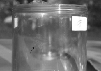
A check was made using FTIR, showing there to be no apparent problem with the polymer, all absorption peaks observed corresponding with the known spectrum for polysiloxane. However, the bag was supplied in a contaminated state with sodium chloride crystals visible on the inner surface in addition to congealed blood. There were relatively few absorption peaks owing to the thickness of the sample (ca 100 micron) However, in order to preserve the device intact, it was necessary to fold the membrane for insertion into the sample chamber of the spectrometer. The bending stress at the fold created a tear, showing the poor strength of the material when subjected to relatively low loads. Optical microscopy showed that the critical fracture extended across the catheter where it joined the bag, and showed how the fracture extended between two shoulders from the bag extension, one above and the other below the crack surface (Fig. 3.22). The survey confirmed the lack of clear features on the fracture surface itself, although a cusp was found at one edge representing the junction of two brittle cracks emanating from a common single origin on one side of the surface (the cusp is at right in Fig. 3.22, with possible origin at left near the shoulder).

ESEM was needed to search for possible defects not detected in the optical microscope. An oblique shot confirmed the fracture to be relatively featureless (Fig. 3.23). There was no evidence for fatigue striations on the surface, so slow intermittent failure across the catheter could be excluded. The zone near the join with the bag showed many defects, and indeed can be just seen at a deep cleft on the right (G) where the bag joins the tube. There appeared to be microcracks present here, which might explain how failure occurred. A more extensive survey revealed more cracks wherever the catheter met the bag, suggesting that either severe stress had created the cracks, or that these zones were inherently weak (Fig. 3.24).


A set of three cracks was seen in the neck near the origin (Figs 3.25 and 3.26) but they were not oriented to initiate a critical crack across the catheter. Just below was the remnant of a larger crack oriented at right angles to the first set, and which was very close to the main critical crack, suggesting that it initiated the final failure (Fig. 3.26). The many sub-critical cracks present in the sample suggested that the load of the whole bag was concentrated at the interface between the bag and catheter, and probably further raised at the sharp corner (Fig. 3.27). The interface might be regarded as the weakest zone for other reasons: it is where the catheter is adhesively bonded to the bag, so if the adhesive, itself a silicone polymer, had been poorly cured, then problems could follow.


3.4.2 Loading pattern
So microscopy had provided good evidence that the device had failed through poor manufacture. But the history of the device was rather more complicated than at first thought. The sequence of infusions of saline solution would be important in explaining why the device failed. The notes of the patient’s consultant showed a steady increase in volume of solution added to the nominal capacity of the bag of 550 ml (Table 3.1). The bag had been fitted by the consultant with 250 ml already present in the bag, and was followed by a further increment of 50 ml on 22 August. A 100 ml portion was added on 5 September, giving a total of 400 ml added to that point. Then on 19 September, a volume of 170 ml was added, exceeding the nominal capacity by 20 ml. It was after this third addition that the patient, Mrs H became disturbed because her chest did not appear to have grown. However, she did not inform her consultant. Further additions were made in October of 100 and 150 ml, and the consultant (presumably observing no increase in bag size) commented that the ‘expander is probably leaking’. Some time after 17 October, Mrs H experienced total loss of volume, and on visiting the surgery, the device was found on exploration to have fractured (Fig. 3.21). A check on the various additions was made by examining the elastomeric seal in the bulb. There were six puncture marks in total, confirming the testimony of the consultant (giving due allowance for a single mis-hit by the hypodermic needle). The rubber seal is designed to retract after puncture so as to retain the contents, although it is unlikely that any leakage occurred here simply because the saline drips down into a bag at a lower level. No defects could be found in the dome, in any case. The final total of 650 ml shown in the consultant’s notes was wrong. Her own records showed that a total of no less than 820 ml of saline had been added by then, well beyond the capacity of the bag.
Table 3.1
Record of fills of breast expander
| Date of fill | Volume of saline added, ml | Comments |
| Aug. 8 | 250 cc | Operation with 550-ml capacity bag inserted by surgeon |
| Aug. 22 | 50 cc | |
| Sept. 5 | 100 cc | Total 400 cc added |
| Sept. 19 | 170 cc | Total 570 ml added |
| Oct. 3 | 100 cc | |
| Oct. 10 | 150 cc | Total 650 cc [sic] added (expander is probably leaking) |
| post-Oct. 17 | – | Patient experiences total loss of fluid from bag |
3.4.3 Conclusion
If the action had come to trial, there is no question that the uncertainty over the total solution added to the expander would have led defendant lawyers to attack the credibility of the consultant. A close relationship had grown up between the claimant and the consultant, and the former decided not to pursue the action for fear of indictment of the consultant. Such circumstances are not uncommon in medical litigation, where existing trauma can be deepened by open discussion of the case in open court.
The case against the manufacturers, Mentor of California, was thus never tested openly, and no discovery made of previous problems with the device, or evidence about tissue expander design and manufacture. It is possible to suggest that the device was defective for the following reasons:
![]() the catheter possessed too small a diameter for the expected load of the full bag
the catheter possessed too small a diameter for the expected load of the full bag
![]() the critical zone where it met the bag was poorly made, with stress raisers present at the deep corners
the critical zone where it met the bag was poorly made, with stress raisers present at the deep corners
![]() the adhesive silicone used to bond bag and catheter was probably over-cured, causing embrittlement.
the adhesive silicone used to bond bag and catheter was probably over-cured, causing embrittlement.
It is not known what quality checks were in place with the device, or what tests had been performed before introduction in the market. The facts pointed to a badly designed product, probably combined with poor manufacture (22), a conclusion supported by evidence from the largest market for medical devices, the USA.
3.4.4 Other cases
Litigation in the USA has been very extensive for a long period following the introduction of breast implants there in the 1980s. The situation was the subject of a class action and Dow Corning declared for bankruptcy, with many millions of dollars being awarded in compensation, mainly for failures and leaking permanent implants. There were also claims for damage caused by leakage of silicone used to fill those implants. Whatever the merit of those claims, there is no doubt that many of the implants fractured in the body, and the devices (like the one featured here) had been under-designed for their role. In the final event (May 2000), the Federal authorities only authorized two manufacturers (Mentor Corporation and Inamed Corporation) to make these devices, and under strict government control (23). They use saline liquid as the infill rather than silicone gel. The design and manufacture of these devices has apparently improved, and other countries which also use them (such as the UK) will benefit from the tough attitude of the US authorities (24,25).
It is not difficult to see why design of silicone implants is so important. Figure 3.28 shows the nature of the problem (26). The tensile strength of silicone elastomer is very low at 25 °C and certainly much lower than EPM (ethylene propylene rubber) or natural rubber (NR). The strength drops very slowly with rise in temperature (unlike the much steeper drops for other rubbers), but this is no consolation for users of the material at body temperatures (ca 40 °C). The material is also very weak in repeated loading, and will fatigue easily at low applied loads, so where body movement is normal and expected, product design must be conservative. It means eliminating or ameliorating stress concentrations (such as the deep corners where the bag meets the catheter, Fig. 3.21), using thick sections of material and ensuring adhesives are cured correctly.

Many attempts have been made to strengthen silicone rubber using a wide variety of different fillers, but a solution is still awaited. In other implants, such as IOLs (intra ocular lenses), silicone is an excellent choice for the replacement lens. They are optically clear and replace a diseased lens, where cataracts have reduced if not eliminated vision in the eye affected. The silicone lens is rolled up and injected through a small slit in the outer eye covering; it then unrolls and fills the cavity. The device is only lightly stressed throughout injection, and almost unstressed when in the eye, so the chance of mechanical failure is very low.
3.5 Failure of sutures
Catgut is a traditional monofilament used to stitch wounds together, but there are now many alternative fibrous materials available. Another natural product, braided silk fibre can also be used, and individual doctors will make a choice appropriate for particular kinds of wound. Stitches which dissolve in body fluids to produce harmless products have been known for many years, the polymers of interest producing non-toxic monomers or starting units. One of the most widely used absorbable suture materials is polyglactin 910, a polysaccharide (commonly sold under the tradename Vicryl). The material is a copolyester of lactic acid and glycolic acid, both of which are harmless products easily excreted by the body:
| —[OCH2CO]— | glycolic acid repeat unit |
| —[OCH(CH3)CO]— | lactic acid repeat unit |
The lactic acid content is about 10% in Vicryl, the repeat units being randomly distributed among blocks of glycolic acid. The crystallinity is lower than pure glycolic acid, but amorphous zones are needed to enhance breakdown by absorbing body fluids. It is hydrolyzed by body fluids at a rate comparable with wound healing, so has disappeared when it has fin-ished holding tissues together and the tissues are self-supporting.
3.5.1 Wound opening
Absorbable sutures are ideal for internal wounds, such as those made after childbirth, but things may not always go to plan. A Mrs P was recovering after successful delivery of a baby boy, using an emergency Caesarean section. The following morning, she began to bleed heavily and was transferred to the labour suite and underwent corrective surgery. However, she suffered continuing problems with the outer wound, which was oozing a pink sticky fluid. The conventional stitches were removed, but about 10 minutes after, she stood up, and the wound opened. She was hor-rified to see her intestines spilling out, an incident witnessed by her shocked partner. She subsequently brought an action against the hospital and makers of the Vicryl sutures used to stitch her uterus.
The medical records show that following delivery of the baby, her uterus was stitched in two layers with Vicryl, and externally with Prolene (polypropylene). She lost a considerable amount of blood during recovery, about 1.44 litres (including that lost at delivery). An ultrasound scan showed her uterus distended with blood clots, about 1 litre being removed under general anaesthetic via her cervix. A clinical note made the next day stated that the ‘uterus had well contracted’. Her outer dressing was changed owing to oozing of fluid, but appeared to have diminished by the next day. Later that same day, the external Prolene sutures were found to be ‘digging into her skin’, so were cut and taped with paper sutures. The following day the wound was clean with only slight oozing, and the paper sutures removed. The attending midwife said that the wound was clean and dry, and the outer Prolene stitches removed ‘easily’. The notes then record wound dehiscence (opening), and she was transferred quickly to theatre where the wound was restitched by another doctor not involved in the original stitching. He made the observation that ‘..all the layers of the wound closure were still present, but the sheath suture had snapped in the middle..’ The statement made it clear that the Vicryl suture had not broken at the knots, and the knots had not slipped. But the failed suture had been discarded after the operation, making investigation of the evidence impossible, a not uncommon problem in medical negligence cases.
3.5.2 Analysis of new suture
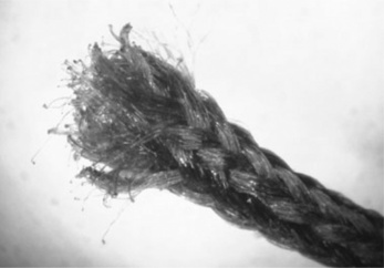
Although the failed suture had been unfortunately lost, equivalent new sutures were made available for inspection. One of the lengths was strained to break on a tensometer, by tying a granny knot to form a loop and then stringing the loop over round supports on the machine. Two tests gave the results:
Tensile breaking load = 70 N, failure strain = 74% (in free fi bre)
Tensile breaking load = 58 N, failure strain = 96% (at knot)
So there is clearly substantial variation in strength, depending on the knot, slippage being a problem and perhaps knot orientation as well. Knots are well-known stress concentrators in ropes and cords, and behave similarly in braided fibre. At the high rate of test, the broken ends showed melting of individual fibres to form blobs of solidified molten polymer (Fig. 3.29). On the other hand, the failure loads of about 7 and 5.8 kg are high compared with expected loads in soft tissue.
The thermal properties of the polymer showed a main melting point of about 200 °C, with subsidiary peaks at 180 °C, 126 °C and 73 °C. It is known that the suture was coated with another polyglactide of different composition, probably exhibited by the large peak at 180 °C while the smaller peaks represent lubricants such as calcium stearate. Finally the fibre proved rapidly soluble (several hours immersion) in strong caustic soda of pH 14, showing that alkaline conditions were needed for hydrolysis. Some body fluids are very slightly alkaline.
3.5.3 Possible causes of failure
So how could the suture have failed at a critical moment? The company Ethicon publishes guidelines on their Vicryl suture (27), stating that the sutures retain 75% of their original tensile strength after 2 weeks implantation in rats, and 50% at three weeks. Since the sutures failed the day after they were emplaced, it was thus unlikely that they failed by dissolution in her body. However, the doctor who restitched the wound said that the Vicryl suture had fractured in the middle. Unfortunately the suture was discarded, so no forensic examination could be made of the remains, and his assertion could not be tested.
It is unusual for cords to break centrally, fractures tending to occur at knots or other attachment points, as experiment had shown. Alternatively, the stitch could simply have not been tied correctly in the first place using approved knots and placements in the soft tissues to be joined together. Evidence from the staff involved in the original stitching was contradictory, but it was known that very junior staff had been involved when the patient was stitched.
3.5.4 Outcome
The action did not proceed in the absence of clear evidence of either medical negligence or a defective suture, and the patient could not be compensated for her distress. It is unfortunate that the physical evidence of failure in many medical cases is frequently lost or discarded, perhaps because the items are disposable anyway. However, it may leave patients uncompensated, and product manufacturers uncertain of the state of their product. If the design and manufacture of products is to be improved, then analysis of failures is vital to determining the cause or causes of the specific problem in question. That task is impossible if the failed products are no longer available for examination. Even a photograph of a failed product is better than no product at all, for much can be learnt from good photographs of failures.
3.6 Failure of breathing tubes
The medical appliances market has developed greatly in recent years with the demand for ever better patient care both in hospital for acute cases, and at home for patients with chronic ailments. Respiratory illnesses are among the most common such ailments, and often require breathing apparatus for supplying the patient with humidified air or oxygen in a controllable way. The breathing equipment for such applications must be made to a very high standard, so that bacterial contamination of the bore is impossible. The case reported here concerns the quality of a large transparent sight tube developed for use in breathing apparatus, the material being injection moulded polysulphone.
The alleged defects related to the quality of finish of the tubes, rather than any structural or functional problems. The manufacturer of the breathing apparatus brought an action against the toolmaker, alleging that the tool for making the tubes was insufficient for moulding sight tubes in polysulphone.
3.6.1 Development of sight tube
The breathing equipment was already in existence when the decision was made to develop a moulded sight tube. The tube sat at the top of a longer metal pipe, and enclosed a float giving visual indication of flow rate in the tube (Fig. 3.30). The float must not fall below the lower marker so as to ensure air or oxygen is being sent to the patient. The transparent tube was machined from acrylic resin (high molecular weight PMMA) to a high quality, but at correspondingly high cost (Fig. 3.31). Not only was the process very labour intensive (and thus expensive), but it also required two parts attached together. Injection moulding would offer economies of scale and part consolidation. A tool was commissioned and the first prototypes in acrylic proved encouraging (Fig. 3.32), although many moulding defects were present, such as severe weld lines (the vertical lines either side of the tube). The decision was made to use UDEL polysulphone (made by Union Carbide), a strange decision in hindsight, given the high cost, and difficult moulding problems presented by this polymer. Apparently, it was felt that alternative transparent plastics like polycarbonate (and acrylic itself) were too susceptible to ESC by attack from common fluids used regularly in hospitals, such as ether and alcohol. The manufacturer clearly envisaged high sales to justify the considerable capital investment needed for an injection moulding tool. Several moulders were then engaged to manufacture the tubes.


3.6.2 Faulty tubes
Since the critical proof of the quality of a tool is in the moulding, the set of about 40 faulty sight tubes held by the plaintiff was central to the dispute. The tubes had been moulded by three different moulders. The tubes were examined for the defects alleged by the plaintiff, with very mixed results. It was clear that the moulders used by the plaintiff had experienced severe problems in moulding polysulphone, largely because of its high melt viscosity and Newtonian behaviour with increasing shear rate in the tool (28).
Most common thermoplastics exhibit shear thinning, which means that the melt viscosity drops substantially in the runners of the tool, and thus makes moulding to shape much easier (Fig. 3.33). Thus LDPE and polystyrene are usually much easier to mould than polycarbonate or polysulphone because their melt viscosity drops fast as the shear rate increases in the narrow runners into the tool cavity. In addition, the tools must be held at high temperature to minimise frozen-in strain in the final product. Accurate temperature control is needed because the melt viscosity is more sensitive to change in temperature than other polymers. The raw granules must be dried before moulding to eliminate surface defects such as splay or splash marks.

Such manufacturing constraints had not been considered by at least one of the moulders, who had needed to buy an oil circulation system to heat the tool so as to mould the polysulphone. Of the many defects seen in the forty or so sample tubes, most if not all were moulding defects caused by poor material preparation, cold tools, and inexperience in moulding this material. Figure 3.34, for example, shows flow lines in the barrel of the tube caused by poor temperature control, the flow lines being visualized by their effect on the shadow cast on graph paper. The tube shown in Fig. 3.35 displays splash marks caused by inadequate drying of the granules, an effect usually appearing on exposed surfaces, and clearly unacceptable for a sight tube where optical clarity was essential. Sink marks in the barrel were relatively common due to low pressures in the tool. Inclusions were seen in some samples (Fig. 3.36). Colouration of the samples was also highly variable (Fig. 3.37), showing a range of temperatures at which the melt and tool had been held.


So what did the study show? Detailed inspection of the available tubes showed that all defects were attributable to moulding problems, and could not be blamed on the tool. To add insult to injury, several samples showed score marks caused by the operator levering the moulding from the cavity. Yet despite the overwhelming evidence of poor moulding practice, the plaintiff decided to proceed with the case.
3.6.3 Trial
The dispute came to trial in London in the mid-1990s. But the trial itself was to yield yet further revelations. In the first place, the lawyer for the plaintiff had been briefed only at the last minute and had a poor grasp of the case essentials, so the opening speech had to be made by the defendant’s barrister! Then it was the plaintiff’s role to enter the witness stand and be questioned. The defendant’s barrister was very well equipped to cross-examine, and as is usual in such trials, much depended on the documentary evidence which had accumulated over the years during which the dispute had festered.
There were reports from the moulders describing the problems of using the tool with polysulphone, but the judge noticed that the last sentence of the last page of one report appeared to be ungrammatical. One possible explanation (offered by the judge) could be that the report had been doctored by photocopying with part obscured by plain paper (perhaps to remove embarssing text), so would not be copied. The judge ordered that the original be produced in open court. It was never produced because the case took another dramatic turn. It was clear from cross-examination on the stand that the plaintiff could not remember key features of the details of the dispute, and when he returned for further cross-examination on the third day of the trial, he broke down and accepted an offer from the defendant to settle the case. The defendant withdrew his counterclaim in return for the plaintiff withdrawing his claim. But there was a sting in the tail of the case: the plaintiff had to pay most of the costs of litigation, including the large costs accrued and bringing the case to trial. The latter costs were greater than the original sum in dispute. So none of the voluminous technical evidence was ever heard in open court, although the judge had clearly read the salient reports in the action.
3.6.4 Lessons
It was never clear why the manufacturer specified polysulphone for the sight tube. Although injection moulding would have lowered unit costs in the long term, it was still a risky venture and depended on achieving high sales of the apparatus. To specify polysulphone was even riskier because the injection moulders chosen were inexperienced in moulding the material. The tool was sufficient to mould the material, but the quality of the end product was mainly in the hands of the moulders and not the tool-maker. It was not a complicated product, having a simple shape. The only element of complexity lay in the screw threads at either end of the tube (requiring a rotating core), but this was not an insuperable problem in moulding.
The dispute should not have continued to a full trial. It should have been resolved much earlier, and saved all the substantial costs of litigation. Indeed, when inspecting the tubes at the plaintiffs’ premises, it was suggested by one of us (PRL) that some form of mediation should be possible. It was rejected. Several attempts were made by the two experts to agree matters before trial, but none succeeded, the plaintiff’s expert supporting his client’s case on every issue. The role of experts should be totally unbiased, seeking to help the court on technical issues only.
3.7 Conclusions
There are many problems in tackling medical device failures. They include
![]() a reluctance to retain and store failed samples returned by hospitals
a reluctance to retain and store failed samples returned by hospitals
![]() the poor quality of reports analyzing samples (poor photography, or no photography at all)
the poor quality of reports analyzing samples (poor photography, or no photography at all)
![]() the tendency to blame users without investigating the problem in depth.
the tendency to blame users without investigating the problem in depth.
They are not normally expected in other areas of engineering failure (although of course not unknown), but tend to recur in case after case of failed medical products. That included the case of the cracked connectors, although two samples were preserved by the mother of the affected baby and supported her evidence. The failed suture disappeared completely, leaving the victim unable to prove negligence. In short, there seems to be little general awareness among product designers of the importance of failure analysis in improving product quality, especially for safety-critical products like catheters and ancillary equipment. It is also certainly true that medical staff are aware of their importance, do often retain samples and report about the circumstances of failure. But so frequently those samples are sent away to the manufacturer and then discarded. That is exactly what happened in the connector case, and indeed their existence could only be inferred from the failure reports and an occasional photocopy made of the devices on letterheads. It is clear that in this particular case, the manufacturer was aware of the problem, and changed the material to polyester but allowed the weak initial designs to continue in service. The device is still supplied, but in a more robust version, and the rate of brittle cracking is apparently much lower.
The literature of medical device failure is voluminous because responsible staff are aware of the safety-critical nature of many of the products used to assist patients. Doctors and consultants do report and describe the failures encountered in their practice, both in technical and professional journals, and often about individual pieces of equipment. They are an invaluable aid for investigators researching specific designs. However, not all relevant details are published as might be hoped, such as the materials of construction or the loads to which they have been exposed. But the stresses experienced by implants such as breast expanders or external devices like catheters are often difficult to estimate with any degree of accuracy. The traditional engineering approach involves providing products with a high safety margin, using very conservative estimates of load so that the device should be capable of surviving normal loads without failure. Standards also provide a useful way of assuring medical staff that a medical product will resist normal handling and body stresses. But standards authorities usually lag by several years, so that standards appear after failures have been widespread. The standard for mammary implants, for example, only appeared in 2000, several years after the first failures were experienced by patients (29). The standard describes numerous tests to evaluate the mechanical strength of implants, and if applied rigorously, should help to improve product performance. Fatigue behaviour remains uncertain, however, especially when body loads can vary so greatly from person to person, tending to be higher the younger the patient. The artificial hip joint is perhaps the most obvious implant that will experience millions of cycles during its lifetime.
To the mechanical problems must be added the effects of exposure to different fluids in many different environments. They include liquids used for disinfection of hospital surfaces (strong detergents, bleach and alcohols) as well as drug carrier fluids, and anaesthetics such as ether. The implant is exposed to many different body fluids and active enzymes, and must be tested against all expected environments before use in humans. Polymers are susceptible to many fluids, especially if products are made with significant degrees of residual strain, such as those produced by cold moulding. Brittle cracking may follow contact with active agents, often initially as hairline cracks, but which then grow along the path of greatest residual strain or chain orientation. Such cracks are very difficult to spot by medical staff, who naturally usually have more important jobs. When those cracks grow to completion, a product may leak internal fluids or simply fall apart, and it is usually then that staff notice the problem. If the device failure is a serious threat to the patient, then emergency action is needed, and the failure reported. Manufacturers must take those reports extremely seriously to avert further failures, and not simply blame staff for product abuse. All such failures need investigation by qualified engineers to locate the fault or defects, and recommendations accepted, if medical device design is to improve in the future. The alternative is further accidents, and patient injury, or worse.
3.8 References
[1] Holden, G., Legge, N.R., Quirk, R., Schroeder, H.E. Thermoplastic Elastomers, 2nd edn. Hanser Publishers; 1996.
[2] Adams, RK, Hoeschle, GK and Witsiepe, WK, Thermoplastic Polyether Ester Elastomers, in Holden et al., op cit.
[3] Gauvin, P., Philippart, J.-L., Lemaire, J. Photo-oxydation de polyether-block-polyamides. Makromol. Chem. 1985; 186:1167–1180.
[4] Elf Atochem tech brochures, available on the web at http://www.pebax.com.
[6] Lewis, P.R., Gagg, C. Failure of an Epidural Catheter. Engineering Failure Analysis. 2009; 16(6):1805–1815.
[7] Scheirs, J., Compositional and Failure Analysis of Polymers: a Practical Approach. John Wiley & Sons Ltd, 2000:352.
[8] , Conical fittings with a 6% (Luer) taper for syringes, needles and certain other medical equipment, 1986. [ISO 594/1, EN 20594-1 (1993).].
[9] Lewis, P.R. Environmental stress cracking of polycarbonate catheter connectors. Engineering Failure Analysis. 2009; 16(6):1816–1824.
[10] Stubstad, J., Female Luers – The Frequent Failers. ANTEC Proceedings. 1992:291–293.
[11] Stubstad, J., Troubleshooting Plastics. Medical Device and Diagnostic Industry. 1992. [100–103 April].
[12] Vilardi, J., Franck, L.S., Powers, R. ECMO Accidents: a survey of the incidence of mechanical failure and user error. Neonatal Network. 1992; 11:25–32.
[13] Niles, S.C., Ploessl, J., Sutton, R.G.T., Steinberg, J.B. Oxygenator Failure due to contact with Bathing Alcohol. J Extra-corporeal Technology. 1992; 24:69–71.
[14] Kwan, E.S.K., Stich, R.A.H., Shrem, L.A. Salvage of a Flow-directed Microcatheter after Hub Failure. Am J Neuroradiology. 1996; 17:868–869.
[15] Lewis, P.R., Ward, R.J. Polishing, Thinning and Etching of Polycarbonate. J Coll and Interface Sci. 1974; 47:661.
[16] Kambour, R.P. A review of crazing and fracture in thermoplastics. Macromol Revs. 1973; 7:1. Moskala, E.J., Jones, M., Evaluating ESC of Medical Plastics, Medical Plastics and Biomaterials, May 1996.
[17] McElwee, D., Snyder, E.J. The use of tapered plastic luer connectors in neonatal extracorporeal membrane oxygenation. Heart and Lung. 1996; 25:324–329.
[18] Federal Food and Drugs Administration website at www.fda.gov for several databases dealing with product failure.
[19] Mueller, R., Sanborn, T. The History of Interventional Cardiology. Am Heart J. 1995; 129:146–172.
[20] Myler, R., Stertzer, S., Coronary and Peripheral Angioplasty: Historic PerspectiveTopol, E., eds. Textbook of Interventional Cardiology, 2nd edn, Vol. 1. Philadelphia: WB Saunders Co, 1993.
[21] King, S.B. Angioplasty From Bench to Bedside to Bench. Circulation. 1996; 93:1621–1629.
[22] Lynch, W., Handbook of Silicone Rubber Fabrication. Van Nostrand Reinhold. 1978.
[23] FDA, Study of rupture of silicone gel filled breast implants, available at http://www.fda.gov.
[24] Young, V.L., Watson, M.E. Breast implant research: where we have been, where we are, where we need to go. Clinic in plastic surgery. 2001; 28(3):451–483.
[25] Brandon, H.-J., et al. Variability in the properties of silicone gel breast implants. Plastic and Reconstructive Surgery. 2001; 108(3):647–655.
[26] Blow, C.M., eds., eds. Rubber Technology and Manufacture, Newnes Butterworth; 135, 1971.
[27] Ethicon website at http://www.ethicon.com.
[28] , Union Carbide technical brochure. Moulding of Udel polysulphones. 1995.
[29] British Standards, Non-active surgical implants – Body contouring implants – Specific requirements for mammary implants, BS EN 12180:2000.