
What other factors influence the design process?

A CENTRAL theme of this book is that engineering design is usually done by teams. Design teams usually include not only engineers, but also manufacturing experts (who may be industrial engineers), marketing and sales professionals, reliability experts, cost accountants, lawyers, and so on. Such teams are concerned with understanding and optimizing the product under development for its entire life, including its design, development, manufacturing, marketing, distribution, use, and, eventually, disposal. Concern with all of these areas, coupled with the need to reduce the time to bring a product to market, has led to what is known as concurrent engineering. Concurrent engineering means that a multidisciplinary design team works simultaneously and in parallel to design a product, a manufacturing approach, a distribution scheme, user support, maintenance, and ultimately disposal. While it is beyond the scope of this book to explore concurrent engineering in depth, it is important that engineers understand and appreciate these related fields that influence both the initial design and the full life cycle of a product.
Engineers have always sought to realize various desirable attributes to some degree in their designs, embodied in the design process as objectives. This is often referred to as “design for X,” where X is an attribute such as manufacturing, maintainability, reliability, or affordability. Designers and engineers also refer to them with a different name, the -ilities, because many of these desirable attributes are expressed as nouns that have an “-ility” suffix. As designers, we can use the idea of the product life cycle to guide us through some of these X's. Since most products are designed to be built, sold, used, and then disposed of, we can look first at design for manufacturing and assembly, and then at design for use, including reliability and maintainability, and lastly, at design for sustainability. We have already considered design for affordability in Chapter 13, where we look at economic aspects of design. All these related concepts can also be considered aspects of quality, which we considered when we looked at quality function deployment and the house of quality.
14.1 DESIGN FOR PRODUCTION: CAN THIS DESIGN BE MADE?
In many cases, a designed artifact will be produced or manufactured in large quantities. In recent years, companies have come to learn that the design of a product can have an enormous impact on the methods and costs of producing it. Toward this end, globally competitive industries such as the automotive and consumer electronics industries routinely consider how a product is manufactured during the earliest stages of design. A significant driver of this concern is the number of products being manufactured, which may allow for the economies of scale that we discussed in Chapter 13. Further, the time it takes to get a product to the consumer, known as the time to market, defines a company's ability to shape a market. Design processes that anticipate manufacturing issues can be key elements in speeding products through to commercial production.
14.1.1 Design for Manufacturing (DFM)
Design for manufacturing (DFM) is design based on minimizing the costs of production and/or the time to market for a product, while maintaining an appropriate level of quality. The importance of maintaining an appropriate level of quality cannot be overstated because without an assurance of quality, DFM is reduced to simply producing the lowest cost product.
DFM begins with the formation of the design team. In commercial settings, design teams committed to DFM tend to be multidisciplinary, and they include engineers, manufacturing managers, logistics specialists, cost accountants, and marketing and sales professionals. Each brings particular interests and experience to a design project, but all must move beyond their primary expertise to focus on the project itself. In many world-class companies, such multidisciplinary teams have become the de facto standard of the modern design organization.
Manufacturing and design tend to interact iteratively during product development. That is, the design team itself discovers a possible problem in producing a proposed design or learns of an opportunity to reduce production costs or timing, and the team then reconsiders its design. Similarly, a design team may be able to suggest alternative production approaches that lead manufacturing specialists to restructure processes. In order to achieve fruitful and synergistic interaction between the manufacturing and design processes, it is important that DFM be considered in each and every one of the design phases, including the early conceptual design stages.
A basic methodology for DFM consists of six steps:
- estimate the manufacturing costs for a given design alternative;
- reduce the costs of components;
- reduce the costs of assembly;
- reduce the costs of supporting production;
- consider the effects of DFM on other objectives; and
- if the results are not acceptable, revise the design once again.
This approach clearly depends upon an understanding of all the objectives of the design; otherwise the iteration called for in Step 6 cannot occur meaningfully. An understanding of the economics of production is also required. This topic is usually taught in industrial engineering courses, or courses in manufacturing. In addition to these areas, however, there are engineering and process decisions made by the design team that can directly influence the cost of producing a product. Some processes for shaping and forming metal, for example, cost much more than others and are called for only to meet particular engineering needs. Similarly, some types of electronic circuits can be made with high-volume, high-speed production machines, while others require hand assembly. Some design choices that require higher costs for small production runs may actually be less expensive if the design can also be used for another, higher volume purpose. In each of these instances, we can complete a successful design only by combining deep knowledge of manufacturing techniques with deep design experience.
There are some specific things that design teams can keep in mind when doing DFM. First of all, consulting with experts on manufacturing can often reveal manufacturing techniques that will (or will not) work with your design. Whether they are faculty members at a university, experts at the client's firm, or even retired manufacturing engineers, tapping into their knowledge is tremendously helpful for the designer. Second, production costs can usually be reduced by using commercially available inputs rather than custom parts. The use of off-the-shelf components will also make cost estimation simpler, since there are catalogs listing specifications and prices. Finally, DFM must always be done with the client's objectives in mind—in some fields, ease of manufacturing or even reduced costs may not be uppermost in the client's mind, especially if lives are at stake.
14.1.2 Design for Assembly (DFA)
Design for assembly is a related, but formally different type of design for X. Assembly refers to the way in which the various parts, components, and subsystems are joined, attached, or otherwise grouped together to form the final product. Assembly can be characterized as consisting of a set of processes by which the assembler (1) handles parts or components (i.e., retrieves and positions them appropriately relative to each other), and (2) inserts (or mates or combines) the parts into a finished subsystem or system. For example, assembling a ball-point pen might require that the ink cartridge be inserted into the tube that forms the handgrip, and that caps be attached to each end. This assembly process can be done in a number of ways, and the designer needs to consider approaches that will make it possible for the manufacturer to reduce the costs of assembly while maintaining high quality in the finished product. Clearly then, assembly is a key aspect of manufacturing and must be considered either as part of design for manufacturing or as a separate, yet strongly related design task.
Because of its central place in manufacturing, a great deal of thought has been put into development of guidelines and techniques for making assembly more effective and efficient. Some of the approaches typically considered are:
- Limiting the number of components to the fewest that are essential to the working of the finished product. Among other things, this implies that the designer will differentiate between parts that could be eliminated by combining other parts and those that must be distinct as a matter of necessity. The usual issues for this are to identify:
- parts that must move relative to one another;
- parts that must be made of different materials (for strength, for example, or insulation); and
- parts that must be separated in order for assembly to proceed.
- Using standard fasteners and/or integrating fasteners into the product itself. Using standard fasteners also allows an assembler to develop standard routines for component assembly, including automation. Reducing the number and type of fasteners allows the assembler to construct a product without having to retrieve as many components and parts. The designer should also consider that fasteners tend to induce stress concentrations and may thus cause reliability concerns.
- Designing the product to have a base component on which other components can be located (including designing for the assembly to proceed with as little motion of the base component as possible). This guideline enables an assembler, whether human or machine, to work to a fixed reference point in the assembly process and to minimize the degree to which the assembler must reset reference points.
- Designing the product to have components that facilitate retrieval and assembly. This may include elements of detailed design that, for example, reduce the tendency of parts and subassemblies to become tangled with one another, or designing parts that are symmetric, so that once retrieved they can be assembled without turning to a preferred end or orientation.
- Designing the product and its component parts to maximize accessibility, during both manufacturing and subsequent repair and maintenance. While it is important that the components be efficient in their use of space, the designer must balance this need with the ability of an assembler or repairer to gain access to and manipulate parts, both for initial fabrication and later replacement.
While these guidelines and heuristics represent only a small set of the design considerations that make up design for assembly, they provide a starting point for thinking about both DFA and DFM. A central principle in both is that quality, and specifically functionality, cannot be sacrificed for the sake of manufacturing or assembly.
14.1.3 The Bill of Materials and Production
Effective design for manufacturing and assembly requires a deep understanding of production processes, among the most important of which are ways to plan and control inventories. A common inventory planning technique is materials requirements planning (MRP). It utilizes assembly drawings to develop a bill of materials (BOM) and an assembly chart—sometimes wittily called a “gozinto” chart—that shows the order in which the parts on the BOM are put together. As we saw in Chapter 13, the BOM is a list of all of the parts, including the quantities of each part required to assemble a designed object. We noted that the BOM is also used when estimating some of the costs of producing the designed artifact.
When a company has determined the size and timing of its production schedule, production planners can determine the size and timing of inventory orders. (Most companies now use just in time delivery of parts as they try to avoid carrying large inventories of parts that are paid for but not generating revenues until after they are assembled and shipped.) The importance of the assembly drawings and the BOM in managing the production process cannot be overstated. To be effective, the design team must not only follow accurate methods of reporting their design, but the entire organization must be committed to the discipline that any design changes, or engineering change orders, will be reported accurately and thoroughly to all the affected parties. Most organizations have formal procedures for recording and managing changes to the design and production process.
A final point to note is that manufacturing concerns include both logistics and distribution, so that these elements have also become an important part of design for manufacturing and assembly. Many companies forge links between the suppliers of materials needed to make a product, the fabricators who manufacture that product, and the channels needed to efficiently distribute the finished product. This set of related activities, often referred to as the supply chain, requires a designer to understand elements of the entire product life cycle. It is beyond our scope to explore the role of supply chain management in design, except to note that in many industries, successful designers understand not only their own production and manufacturing processes, but also those of their suppliers and their customers.
14.2 DESIGN FOR USE: HOW LONG WILL THIS DESIGN WORK?
Design for use ties together the designer–client–user triangle in a powerful way. We often hear the words “user friendly” applied to describe a product, but this is only meaningful if made specific. This specificity may include interfaces between the designed system and the user, skills requirements, physical demands on the user (captured in the field of ergonomics), and even how well the system works relative to unintended applications. Limitations of time and space require us to describe only a few of the rich topics underlying design for use; in this section we consider reliability and maintainability.
Most of us have a personal, visceral understanding of reliability and unreliability as a consequence of our own experience with everyday objects. We say that the family car is unreliable, or that a good friend is very reliable—someone we can count on. While such informal assessments are acceptable in our personal lives, we need greater clarity and accuracy when we are functioning as engineering designers. Thus, we now describe how engineers approach reliability, along with its sister concept, maintainability.
14.2.1 Reliability
To an engineer, reliability is defined as “the probability that an item will perform its function under stated conditions of use and maintenance for a stated measure of a variate (time, distance, etc.).” This definition has a number of elements that warrant further comment. The first is that we can properly measure the reliability of a component or system only under the assumption that it has been or will be used under some specified conditions. The second point is that the appropriate measure of use of the design, called the variate, may be something other than time. For example, the variate for a vehicle might be miles, while for a piece of vibrating machinery the variate might be the number of cycles of operation. Third, we must examine reliability in the context of the functions discussed in Chapter 6, which emphasizes the care we should take in developing and defining the functions that a design must perform. Finally, note that reliability is treated as a probability, and hence can be characterized by a distribution. In mathematical terms, this means that we can express our expectations of how reliable, safe, or successful we expect a product or a system to be in terms of a cumulative distribution function or a probability density function.
In practice, our use of a probabilistic definition enables us to consider reliability in the context of the opposite of success, that is, in terms of failure. In other words, we can frame our consideration of reliability in terms of the probability that a unit will fail to perform its functions under stated conditions within a specified window of time. This requires us to consider carefully what we mean by failure. British Standard 4778 defines a failure as “the termination of the ability of an item to perform a required function.” This definition, while helpful at some level, does not capture some important subtleties that we, as designers, must keep in mind: It doesn't capture the many kinds of failures that can afflict a complex device or system, their degree of severity, their timing, or their effect on the performance of the overall system.
For example, it is useful to distinguish between when a system fails and how it fails. If the item fails when in use, the failure can be characterized as an in-service failure. If the item fails, but the consequences are not detectable until some other activity takes place, we refer to that as an incidental failure. A catastrophic failure occurs when a failure of some function is such that the entire system in which the item is embedded fails. For example, if our car breaks down while we're on a trip and needs a repair in order for us to complete the trip, we would call that an in-service failure. An incidental failure might be some part that our favorite mechanic suggests we replace during the routine servicing of our car. A catastrophic, accident-causing failure might follow from the failure of a critical part of the car while we are driving at freeway speeds. Each type of failure has its own consequences for the users of the designed artifact, and so must be considered carefully by designers.
We often specify reliability by using measures such as the mean time between failures (MTBF), or miles per in-service failure, or some other metric. However, we should note that framing the definition of reliability in terms of probabilities gives us some insight into the limitations inherent in such measures. Consider the two failure distributions shown in Figure 14.1. These two reliability probability distributions have the same mean (or average), that is, MTBFa = MTBFb, but they have very different degrees of dispersion (typically measured as the variance or standard deviation) about that mean. If we are not concerned with both mean and variance, we may wind up choosing a design alternative that is seemingly better in terms of MTBF, but much worse in terms of variance. We may even choose a design for which the MTBF is acceptable, but for which the number of early failures is unacceptably high.

Figure 14.1 Failure distributions (also called probability density functions) for two different components. Note that both curves have the same value of MTBF, but that the dispersions of possible failures differ markedly. The second design (b) would be viewed as less reliable because more failures would during the early life of the component (i.e., during the time interval t0 ≤ t ≤ t1).
One of the most important reliability issues for a designer is how the various parts of the design come together and what the impact is likely to be if any one part does fail. Consider, for example, the conceptual sketch of the series system design, shown in Figure 14.2. It is a chain of parts or elements, the failure of any one of which would break the chain, which in turn will cause the system to fail. Just as a chain is no stronger than its weakest link, a series system is no more reliable than its most unreliable part. In fact, the reliability—or probability that the system will function as designed—of a series system whose individual parts have reliability (or probability of successful performance) Ri(t) is given by
RS(t) = R1(t) · R2(t) ····· Rn(t)

Figure 14.2 This is a simple example of a series system. Each of the elements in the system has a given reliability. The reliability of the system as a whole can be no higher than that of any one of the parts because the failure of any one part will cause the system to cease operating.
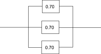
Figure 14.3 This is a simple example of a parallel system. Note that every one of the components must fail in order for the system to cease working. While such a system has high reliability, it is also quite expensive. Most designers seek to incorporate such redundancy when necessary, but look for other solutions wherever possible.
or
Here RS(t) is the reliability of the entire series system, and ![]() is the product function. We see from eq. (14.1) that the overall reliability of a series system is equal to the product of all of the individual reliabilities of the elements or parts within the system. This means that if any one component has low reliability, such as the proverbial weak link, then the entire system will have low reliability and the chain will likely break.
is the product function. We see from eq. (14.1) that the overall reliability of a series system is equal to the product of all of the individual reliabilities of the elements or parts within the system. This means that if any one component has low reliability, such as the proverbial weak link, then the entire system will have low reliability and the chain will likely break.
Designers have long understood that redundancy is important for dealing with the weakest link phenomenon. A redundant system is one in which some or all of the parts have backups or replacement parts that can substitute for them in the event of failure. Consider the conceptual sketch of the parallel system of three parts or elements shown in Figure 14.3. In this simple case, each of the components must fail in order for the system to fail. The reliability RP(t) of this entire parallel system is given by
RP(t)= 1 − [(1 − R1(t)) · (1 − R2(t)) ····· (1 − Rn(t))]
or
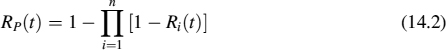
We can see from eq. (14.2) that the reliability of this parallel system (i.e., the probability that the parallel system will operate successfully) is now such that if any one of the elements functions, the system will still function.
Parallel systems have obvious advantages in terms of reliability, since all of the redundant or duplicate parts must fail in order for the system to fail. Parallel systems are also more expensive, since many duplicate parts or elements are included only for contingent use, that is, they are used only if another part fails. For this reason, we must carefully weigh the consequences of failure of a part against failure of the system, along with costs attendant to reducing the likelihood of a failure. In most cases designers will opt for some level of redundancy, while allowing other components to stand alone. For example, a car usually has two headlights, in part so that if one fails the car can continue to operate safely at night. The same car will usually have one radio, since its failure is unlikely to be catastrophic. The mathematics of combining series and parallel systems is beyond our scope, but we clearly have to learn and use them to design systems that have any impact on the safety of users. Put simply, redundancy usually increases both reliability and costs.
Designers can consider modes of failure and develop estimates of reliability only if they truly know how components might fail. Such knowledge is gained by performing experiments, analyzing the statistics of prior failures, or by carefully modeling the underlying physical phenomena. Designers lacking deep experience in understanding component failure should consult experienced engineers, other designers, users, and the client in order to ascertain that an appropriate level of reliability is being designed into the system. Often the experience of others allows a designer to answer reliability questions without performing a full set of experiments. For example, the appropriateness of different kinds of materials for various designs can be discussed with materials engineers, while properties such as tensile strength and fatigue life are documented in the engineering literature.
We can take specific steps to design for reliability. This is because failure generally is caused by inadequate design, manufacturing defects, use outside of specified conditions, or improper use. In each of these cases, the thoughtful designer can anticipate problems and “retire risk.”
- Inadequate design, for example, can be addressed in part by material selection: is the material being used adequate for the intended use? In Chapter 12, we looked at the relationship between designing for strength and stiffness in our ladder. That material selection process can also inform us about the overall expected life of our design. While beyond our scope, professional engineers need to understand and consider material properties such as tensile strength, hardness, fatigue life, and creep in selecting materials that are used in critical environments.
- Manufacturing defects are best resolved by attention to DFM above, but we can also ask specific questions regarding the nature of proposed manufacturing and assembly processes and their impact on reliability. For example, are defects in manufacturing revealed during the process? If not, are there tests we can conduct to uncover them, or at least estimate their likelihood? When defects are revealed, are there procedures in place to allow us to reject substandard parts before putting them into use? If not, is development and application of such tests part of the design team's expected work?
- Looking at use-related failures, we can ask whether operation of our design is sufficiently clear to end users that the artifact will only be used in the manner and conditions intended. How do we know that? Has our testing and evaluation scheme given us insight into how the system might be used by someone outside the design team's orbit? Have we designed in a way that will permit visible labeling of dangerous or unsafe practices or environments?
Even at the design stage we need to consider the above questions if we are going to produce a reliable design. But that raises a final question—how reliable does the product need to be to meet our client's needs? Asking that question leads us all the way back to our consideration of objectives and metrics in Chapter 4. The proper metric for reliability is a number—the probability that the system will function under specified conditions for a specified amount of usage. The more critical the system is (e.g., air traffic control electronics), the higher that number will need to be.
14.2.2 Maintainability
Our understanding of reliability also suggests that many of the systems that we design will fail if they are used without being maintained, and that they may need some amount of repair even when they are properly maintained. This fact of life leads engineers to consider how to design things so that necessary maintenance can be performed effectively and efficiently. Maintainability can be defined as “the probability that a failed component or system will be restored or repaired to a specific condition within a period of time when maintenance is performed within prescribed procedures.” As with our definition of reliability, we can learn from this definition.
First, maintainability depends upon a prior specification of the condition of the part or device, and on any maintenance or repair actions, which are part of the designer's responsibilities. Second, maintainability is concerned with the time needed to return a failed unit to service.
Designing for maintainability requires that the designer take an active role in setting goals for maintenance, such as times to repair, and in determining the specifications for maintenance and repair activities in order to realize these goals. This can take a number of forms, including:
- selecting parts that are easily accessed and repaired;
- providing redundancy so that systems can be operated while maintenance continues;
- specifying preventive or predictive maintenance procedures; and
- indicating the number and type of spare parts that should be held in inventories in order to reduce downtime when systems fail.
There are costs and consequences in each of these design choices. For example, a system may be designed with high levels of redundancy to limit downtime during maintenance, like an air traffic control system, but it may have very large attendant capital costs. Similarly, the cost of carrying inventories of spare parts can be quite high, especially if failures are rare. One strategy that has been increasingly adopted in many industries is to work toward making parts standard and components modular. Then spare parts inventories can be used more flexibly and efficiently, and components or subassemblies can be easily accessed and replaced. Any removed subassemblies can be repaired while the repaired system has been returned to service.
If high maintainability has been established as a significant design objective, design teams must take active steps in the design process to meet that goal. A design team should ask itself what maintenance actions reduce failures (especially in-service and catastrophic failures), what elements of the design support early detection of problems or failures (e.g., inspection), and what elements speed the return of failed items to use (e.g., repair). While no one would intentionally design systems to make maintenance more difficult, the world is fraught with examples in which it is difficult to believe otherwise, including a new car in which the owner had to remove the dashboard just to change a fuse.
Several considerations that designers should bear in mind when designing for maintenance and repair include:
- Fault isolation and self-diagnosis: It usually takes time to identify what has gone wrong with a system. As designers we can help reduce this time by building clear indicators into systems that identify the part of that system requires attention.
- Part standardization and interchangeability: Using standard parts in the design helps us to identify the number of parts held in inventories, and to reduce the skills needed to make repairs.
- Modularization and accessibility: Designs that modularize (i.e., package related components together) greatly reduce the time needed to restore a broken system to a working state, especially if the modules are themselves easy to replace. Parts with higher expected failure rates can often be placed in a system in ways that make them accessible without removal of other, functional parts.
If we follow these guidelines as members of a design team, we can better address our design problem, and we will gain a mindset that appreciates and respects users who must ultimately work with the system we are designing.
14.3 DESIGN FOR SUSTAINABILITY: WHAT ABOUT THE ENVIRONMENT?
Some people have come to hold negative views of technology and engineered systems because of the realization that one generation's progress may produce an environmental nightmare for the next. There are certainly enough examples of short-sighted projects (such as irrigation systems that created deserts or flood-control schemes that eliminated rivers entirely) that responsible engineers can feel at least some anxiety about what their best ideas might eventually produce. The engineering profession has come to appreciate these concerns over the past several decades, and has incorporated environmental responsibility directly into their codes of ethical obligations of engineers. The American Society of Civil Engineers (ASCE), for example, specifically directs engineers to “strive to comply with the principles of sustainable development”; the American Society of Mechanical Engineers (ASME) stipulates that “Engineers shall consider environmental impact in the performance of their duties.” A number of tools to understand environmental effects are being introduced into engineering design in order to help with these issues and obligations (e.g., environmental life-cycle assessments (LCAs), which we discuss below). Some of these ethical obligations now take on the force of law, as we see in the requirement that many projects, especially public projects, conduct environmental impact reviews (EIRs).
14.3.1 Environmental Issues and Design
Environmental concerns relevant to design can be organized in any number of ways. Transportation engineering texts, for example, concern themselves with the impacts of engineered systems on water and air quality, while electrical engineering texts consider the effects of power generation and transmission, or focus on the particular environmental effects of some of the solvents and other chemicals associated with producing chips or printed circuit boards. A more general approach is to think in terms of particular aspects of the environment and then consider the likely short- and long-term consequences of design alternatives.
We can often characterize the environmental implications of a design in terms of the effects on air quality, water quality, energy consumption, and waste generation. In each case, we need to address both short-term issues, which may arise as part of design for manufacturing or economic analysis, and long-term issues, which may not come up at all unless the designer raises them. Unfortunately, experience shows that the long-term effects of our design choices can completely overwhelm short-term benefits.
Air quality almost immediately springs to mind when we list environmental concerns related to design. Some urban areas have tremendous smog problems, small towns may have an industry with a large smokestack, and even national forests are experiencing loss of habitat due to acid rain and other air-quality issues. It is important to realize that these enormous problems often begin with relatively small emissions from various steps in the production of everyday objects. Each mile we drive in a car powered by a standard internal combustion engine adds a tiny bit of particulate matter, nitrous oxide, and carbon monoxide to the atmosphere. In addition, refining the fuel, smelting the steel, and curing the rubber for the tires add further emissions to the air. Less obvious but similar air quality problems result from the production of everyday materials in paper bags and plastic toys. In other words, designers concerned about the environment must consider both the manufacture of the product and its use.
Environmentally conscious engineers should also concern themselves with issues of water quality and water consumption. We may take the availability of clean water for granted, but many of the world's major bodies of water are under stress from overuse and pollution. As with air quality, this is a direct result of the multiple uses made of our water supplies. Many states have experienced severe droughts in the recent years, and in the southwestern United States, water is becoming the single biggest environmental constraint on further growth. Effective designers must consider and calculate the water requirements for producing and using their designs. Estimating changes to water resulting from particular designs is of great significance. These can include changes in water temperature (which for large-scale processes can affect fish and other parts of the ecosystem) and the addition of chemicals, particularly hazardous or long-lived compounds.
The production and use of designed systems requires energy. However, the energy demands of a system can be much higher than designers realize, or may come from sources that are particularly problematic environmentally. Several years ago, California faced an energy crisis that led to sporadic blackouts. Design choices about common household appliances such as refrigerators affect an increasingly energy-starved world. The variety of sizes, shapes, and levels of efficiency of refrigerators highlights the many design choices made by engineers and product design teams. Beneath the surface of such devices, however, there are further design choices made by engineers while generating and selecting alternatives. The principal energy consumer in a refrigerator is the compressor, which can be made more energy-efficient by judicious selection of components. Within the refrigerator walls, the use of insulation materials has a tremendous effect on how well cold temperatures are retained. Even door designs and their placement affects how much energy a refrigerator consumes. Designers must approach such projects systematically, applying all of the skills and techniques learned in their engineering science courses, and accounting for the consequences of their design choices.
Products must also be disposed of after fulfilling their useful life. In some cases, perfectly good designs become serious disposal problems. For example, consider the wooden railroad tie used to secure and stabilize trains tracks and distribute the loads into the underlying ballast. Properly maintained and supported, ties treated with creosote typically last more than 30 years, even under heavy loads and demanding weather conditions. Not surprisingly, most railroads use such ties. At the end of their lives, however, the same chemical treatment that made them last so long creates a major disposal problem. Improperly disposed of, the chemicals can leach into water supplies, making them harmful to living things. The ties also emit highly noxious, even toxic, fumes when burned. Thus, managing the waste streams associated with products and systems has become an important consideration in contemporary design. A great solution to one problem has become a problem in itself. The railroad industry has sponsored a number of research projects to explore ways to reuse, recycle, or at least better dispose of used ties, but the results remain to be seen. A more immediately obvious example of waste streams created by new technologies can be found in the many hand-held devices that most of us take for granted. Each new generation of cell phones, personal digital assistants, tablets, and personal computers also creates a new generation of electronic waste to be processed and disposed of. Sadly, there are environmental horror stories surrounding disposal of consumer electronics, particularly in developing countries, who often serve as the dumping ground for such products.
Sometimes the market fails to support the planned post-consumer disposal, even for products designed to be recyclable or reusable. Recycling is the intended final state of many paper and plastic products, for example, but many cities have found it difficult to successfully dispose of recycled paper and so are forced to place it in landfills. Battery companies have tried to develop recycling facilities to capture and control heavy metals and other dangerous waste products, but the small and omnipresent nature of batteries has made this very difficult.
14.3.2 Global Climate Change
Among the most pressing concerns facing us are the effects of climate change, sometimes referred to as global warming. There is overwhelming evidence that the average annual temperatures on the planet are rising, and a very strong consensus in the scientific community that human activity is responsible for some or all of this increase. The consequences of even modest increases in global temperature are likely to be catastrophic for some regions, such as polar ice caps, which are melting at surprising rates, and for some species that depend on particular climate conditions (such as polar bears). Engineers have a special obligation to involve themselves in finding ways to address global climate change, both because they have played a key role in the responsible technologies and because they have skills that can help moderate climate change.
One of the most important elements of global climate change is the extent to which carbon is emitted into the atmosphere, introducing what are referred to as “greenhouse gases.” Many technologies emit carbon in ways that can surprise us, and when these technologies are used extensively the effects can be very significant. Some airplane engine designs, for example, emit very large volumes of carbon as a combustion by-product. Indeed, a pound of grapes flown from Chile to the United States results in six pounds of carbon being emitted into the atmosphere. Aircraft designers are working very hard to find ways to reduce carbon emissions from engines, but much work remains to be done.
Designing to reduce carbon emissions often begins with the measurement of the “carbon footprint” associated with producing the technology. The designer attempts to measure or estimate all the greenhouse gases emitted in all the processes to produce the product in question. This is still a very new analysis technique, and standards and methods are in flux at this time, but responsible engineers will be expected to understand and apply these techniques when designing for sustainability. As measuring the carbon footprint of technologies becomes better understood, the methods will find their way into life-cycle assessment, an important technique described in the Section 14.3.3.
14.3.3 Environmental Life-Cycle Assessments
Life-cycle assessment is a tool that was developed to help product designers understand, analyze, and document the full range of environmental effects of design, manufacturing, transport, sale, use, and disposal of products. Depending on the nature of the LCA and the product, such analysis begins with the acquisition and processing of raw materials (such as petroleum drilling and refining for plastic products, or foresting and processing of railroad ties), and continues until the product has been reused, recycled, or placed in a landfill. LCA has three essential steps:
- Inventory analysis lists all inputs (raw materials and energy) and outputs (products, wastes, and energy), as well as any intermediate outputs.
- Impact analysis lists all of the effects on the environment of each item identified in the inventory analysis, and quantifying or qualitatively describing the consequences (e.g., adverse health effects, impacts on ecosystems, or resource depletion).
- Improvement analysis lists, measures, and evaluates the needs and opportunities to address adverse effects found in the first two steps.
Obviously, one of the keys in LCA is the setting of assessment boundaries. Another is identifying appropriate measures and data sources for conducting the LCA. We cannot expect to find good, consistent data for all of the elements in the LCA, and so we must reconcile information from multiple sources. Because of differing project boundaries, data sources and reconciliation techniques, different analyses may produce different figures for the overall effects of a product, even when they're done in good faith. Therefore, it is very important that we list all the assumptions we've made and document all of the data sources we have used.
Currently, LCA is still in the early stages of development as a tool for engineering designers (and others concerned with the environmental effects of technologies). Notwithstanding its “youth,” however, LCA is already a useful conceptual model for design, and is likely to become increasingly important for the evaluation of complex engineered systems.
14.4 NOTES
Section 14.1: This section draws heavily upon Pahl and Beitz (1996) and Ulrich and Eppinger (2000). In particular, the six-step process is a direct extension of a five-step approach in Ulrich and Eppinger (1995), with the iteration made explicit. Our discussion of DFA is adapted from Dixon and Poli (1995) and Ullman (1997); rules of assembly are cited in many places but are generally derived from Boothroyd and Dewhurst (1989).
Section 14.2: The definition of reliability comes from U.S. Military Standards Handbook 217B (MIL-STD-217B 1970) as quoted in Carter (1986). The failure discussion draws heavily from Little (1991). There are a number of formal treatments of reliability and the associated mathematics, including Ebeling (2010) and Lewis (1987). The definition of maintainability is from Ebeling (2010), as are the guidelines to design for reliability and maintainability.
Section 14.3: Codes of ethics for engineers are discussed further in Chapter 17. Sections 14.3.1 and 14.3.3 draw heavily on Rubin (2001), which also includes a very instructive example of LCA written by Cliff Davidson. The figure for carbon emissions from transporting grapes comes from McKibben (2007). Methodologies for calculating carbon footprints are given in Wiedmann and Minx (2007).