
Here's my design; can you make it?

BEING ABLE to communicate effectively is a critical skill for engineers. We communicate in oral presentations, and through written documents, and technical drawings. We also communicate individually and as members of design teams. We communicate with our client: when we define the design problem; while we work through the design process; and when we portray our final design in standardized, detailed drawings so it can be built. We communicate when we build models or prototypes to demonstrate or evaluate our design's effectiveness. And perhaps as important as anything else, we also communicate when we take our ideas from our heads and commit them to paper. We devote this chapter to creating design drawings, an essential tool for effective engineering communication.
9.1 ENGINEERING SKETCHES AND DRAWINGS SPEAK TO MANY AUDIENCES
Drawing is very important in design because a lot of information is created and transmitted in the drawing process. Design drawings include sketches, freehand drawings, and computer-aided design and drafting (CADD) models that extend from simple wire-frame drawings (e.g., something very much like stick figures) through elaborate solid models (e.g., three-dimensional objects that include color and perspective).

Figure 9.1 Design information adjacent to a sketch of the designed object (after Ullman, Wood, and Craig (1990)). Note how clear and neat this sketch is, and that the notes are in easy-to-read block letters.
In historical terms, drawing is the process of putting “marks on paper.” These marks include both sketches and marginalia, that is, notes written in the margins. Sketches are of objects and their associated functions. Marginalia include notes in text form, lists, dimensions, and calculations. Thus, drawings enable a parallel display of information as they can be surrounded with adjacent notes, smaller pictures, formulas, and other pointers to ideas related to the object being drawn and designed. Putting notes next to a sketch is a powerful way to organize information, certainly more powerful than the linear, sequential arrangement imposed by the structure of sentences and paragraphs. Figure 9.1 illustrates some of these features in a sketch made by a designer working on the packaging for a battery-powered computer clock. (We will say more about the different kinds of sketches in Section 9.2.) The packaging consists of a plastic envelope and the electrical contacts. The designer has written down some manufacturing notes adjacent to the drawing of the spring contact. It would not be unusual for the designer to have scribbled modeling notes (e.g., “model the spring as a cantilever of stiffness …”), or calculations (e.g., calculating the spring stiffness from the cantilever beam model), or other information relating to the unfolding design. Thus, in such an annotated sketch, the designer can provide information about her assumptions, analyses that might be done, or even about how the device will be fabricated.
Marginalia of all sorts are familiar sights to anyone who has worked in an engineering environment. We often draw pictures and surround them with text and equations. We also draw sketches in the margins of documents, to elaborate a verbal description, to fortify understanding, to indicate more emphatically a coordinate system or sign convention. It is thus no surprise that sketches and drawings are essential to engineering design. In some fields (e.g., architecture), sketching, geometry, perspective, and visualization are acknowledged as the very underpinnings of the field.
In brief, graphic images are used to communicate with other designers, the client, and the manufacturing organization. Sketches and drawings:
- serve as a launching pad for a brand-new design;
- support the analysis of a design as it evolves;
- simulate the behavior or performance of a design;
- record the shape or geometry of a design;
- communicate design ideas among designers;
- ensure that a design is complete (as a drawing and its associated marginalia may remind us of still-undone parts of that design); and
- communicate the final design to the manufacturing specialists.
We will now present some more specifics about design sketches and the different kinds of engineering drawings.
9.2 SKETCHING
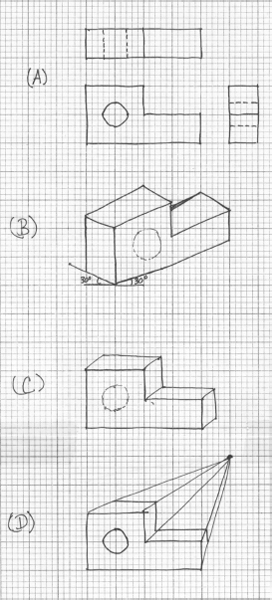
Sketching is a powerful tool in design because it enables us to convey our design ideas to others quickly and concisely. There are several types of sketches that designers routinely use to convey design information, including (see Figure 9.2):
- Orthographic sketches (Figure 9.2a) lay out the front, right and top views of a part.
- Axonometric sketches (Figure 9.2b) start with an axis, typically a vertical line with two lines 30° from the horizontal. This axis forms the corner of the part. The object is then blocked in using light lines, with the overall size first. Then vertical lines are darkened, followed by other lines. All lines in these sketches are either vertical or parallel to one of the two 30° lines. Details of the part are added last.
- Oblique sketches (Figure 9.2c) are probably the most common type of quick sketch. The front view is blocked in roughly first, depth lines are then added, and details such as rounded edges are added last.
- Perspective sketches (Figure 9.2d) are similar to oblique sketches in that the front view is blocked in first. Then a vanishing point is chosen and projection lines drawn from the points on the object to the vanishing point. The depth of the part is then blocked in using the projection lines. Finally, as in the other sketches, details are added to the part.
Each of these sketches provides a framework for putting design thoughts on paper. They may also serve as informational starting points for other design activities, for example, building physical models and prototypes. These quick sketches can also be enhanced if we pay attention to their proportions and if we annotate them:
- Proportion control: It is extremely useful to show the relative sizes of parts, components, or features in a sketch. That's why it is generally a good idea to sketch designs on graph paper, because it is easier to control those relative sizes using the graph paper's grid, without having to make measurements with a ruler. It is also a good idea to think ahead of the components to be sketched before drawing actually begins: First “block in” the overall length and width of a part, to lay out the largest component first, and then add details.
Figure 9.2 Four types of sketches of the same object: (a) orthographic, (b) axonometric, (c) oblique, and (d) perspective.
- Annotation: Clear, easily read notes on sketches are tremendously useful in conveying the meaning behind the sketched ideas. We should make those annotations as clear and easy to read as possible. For example, it is generally useful to follow the familiar architectural style of using evenly spaced block letters; they are generally much clearer than cursive scribbles.
We saw a very good sketch in Figure 9.1: It was clear, drawn proportionately, and well annotated, using the block lettering we just suggested. Figure 9.3 shows two oblique sketches taken from team A's final report on the Danbury arm support project. These detailed design sketches have a rough visual appeal, and chances are that they took much more time to produce than sketches done early in the design process, where the focus is on getting out concepts quickly. We note, however, that the lettering in Figure 9.3 is uneven and hard to read in places. Block lettering would have taken no more time, and would have produced an overall visual image that is much easier to read and perhaps more impressive.

Figure 9.3 Sketches of two of the design alternatives produced by team A for the Danbury arm support. Adapted from Attarian et al. (2007).
9.3 FABRICATION SPECIFICATIONS: THE SEVERAL FORMS OF ENGINEERING DRAWINGS
In addition to communicating with client(s) about a project, a design team must also communicate with the maker or manufacturer of the designed artifact. Often, the only “instructions” that the fabricator sees are those representations or descriptions of the designed object that are included in the final design drawings. This means that these representations must be complete, unambiguous, clear, and readily understood. The relevant question is: How do we ensure that the design as built will be exactly the design that we designed?
The answer is straightforward: When we communicate design results to a manufacturer, we must think very carefully about the fabrication specifications that we are creating in drawings, as well as those we write. This means we must ensure that our drawings are both appropriate to our design and prepared in accordance with relevant engineering practices and standards.
9.3.1 Design Drawings
There are several different kinds of drawings that are formally identified in the design process:
- Layout drawings are working drawings that show the major parts or components of a device and their relationship (see Figure 9.4). They are usually drawn to scale, do not show tolerances, and are subject to change as the design process evolves.
Figure 9.4 A layout drawing that has been drawn to scale, does not show tolerances, and is certainly subject to change as the design process continues. Adapted from Boyer et al. (1991).
Figure 9.5 A detail drawing that includes tolerances and that indicates materials and lists special processing requirements. It was drawn in conformance with ANSI drawing standards. Adapted from Boyeretal. (1991).
- Detail drawings show the individual parts or components of a device and their relationship (see Figure 9.5). These drawings must show tolerances, and they must also specify materials and any special processing requirements. Detail drawings are drawn in conformance with existing standards, and are changed only when a formal change order provides authorization.
- Assembly drawings show how the individual parts or components of a device fit together. An exploded view is commonly used to show such “fit” relationships (see Figure 9.6). We identify components by part numbers or entries on an attached bill of materials; they may include detail drawings if the major views in the detail drawings cannot show all of the required information.
Figure 9.6 This assembly drawing uses an exploded view to show how some of the individual parts of an automobile fit together. The individual components are identified by a part number or an entry on a bill of materials (that is not shown here). Adapted from Boyer et al. (1991).


In describing the three principal kinds of mechanical design drawings, we have used two technical terms that need definition: tolerances and standards. First, drawings show tolerances when they define the permissible ranges of variation in critical or sensitive dimensions. As a practical matter, it is impossible to make any two objects exactly the same. They may appear to be the same because of our limited ability to distinguish differences at extremely small or fine resolution. When we are producing many copies of the same thing intended to function in the same way, we must limit as best we can any variation from their ideally designed form. Tolerances formally prescribe these limits. The values chosen for tolerances on a specific part are often driven by the function of that part and by the manufacturing processes available.
Second, we have also noted the existence of drawing standards. Standards explicitly articulate the best current engineering practices in routine or common design situations. Thus, standards indicate performance bars that must be met for drawings (e.g., ASME Y14.5–1994 Dimensions and Tolerancing), for the fire safety of buildings built within the United States (e.g., the Life Safety Code of the National Fire Protection Association), for boilers (e.g., the ASME Pressure Vessel Code), and so on. The American National Standards Institute (ANSI) serves as a clearinghouse for the individual standards written by professional societies (e.g., ASME, IEEE) and associations (e.g., NFPA, AISC) that govern various phases of design. ANSI also serves as the national spokesman for the United States in working with other countries and groups of countries (e.g., the European Union) to ensure compatibility and consistency wherever possible. A complete listing of U.S. product standards can be found in the Product Standards Index. The drawing standards specified in ASME Y14.5M-1994 are described in some depth in Appendix B.
9.3.2 Detail Drawings
We now turn to the requirements for detail drawings. These drawings are used to communicate the details of our design to the manufacturer or machinist. They must contain as much information as possible while being both as clear and as uncluttered as possible. Engineers and machinists have developed a system of standard symbols and conventions to meet this goal: geometric dimensioning and tolerancing (GD&T). These standards and conventions are described briefly here and in more detail in Appendix B.
Suppose we were designing a device, say a three-hole punch (see Exercise 9.1) or a simple desk lamp or a hammer, with the goal of having someone fabricate or make our design. What do we have to put down on paper, in both words and pictures, for us to be sure that the maker would fabricate exactly what we want? If we set down that description on paper and handed it to a friend or colleague, would she know exactly what we intend and want? This imaginary exercise is far more difficult than it sounds. In fact, imagine even a simpler version, akin to the way we introduced design problems. Supposed we had said to someone, “Please join this piece of metal to that piece of wood.” Is that a sufficient description of what we mean, for example, if we're attaching steel rails to wooden railroad ties, or if we're designing a clock to be housed in an elegant piece of grained maple?
The point is that as engineers we require common standards by which we can communicate our designs to those makers or machinists or fabricators who will actually make or build them. There are certain essential components that every drawing must have to ensure that it is interpreted as it is intended. These components include:
- standard drawing views;
- standard symbols to indicate particular items;
- clear lettering;
- clear, steady lines;
- appropriate notes, including specifications of materials;
- a title on the drawing;
- the designer's initials and the date it was drawn;
- dimensions and units; and
- permissible variations, or tolerances.
Figure 9.7 displays a technical drawing that conforms to the GD&T system and ASME standards. It shows a screwdriver handle that Harvey Mudd students manufacture as part of our introductory design course. Note the descriptive title, the date on the drawing, and the designer's initials. In addition, a note was included to specify the material as cast acrylic and that the finish should be polished. Dimensions and tolerances, specified in accord with GD&T standards and rules, are carefully detailed on the drawing. The various symbols that appear on the drawing are part of the GD&T language (and are described in more detail in Appendix B).

Figure 9.7 A detail drawing of the handle of a screwdriver. This drawing uses a set of symbols and the particular placement of these symbols conveys information about the size and location of certain features of the screwdriver handle. In addition, the drawing contains information about the materials to be used, the finish of the part, the person who created it, and the date it was created. Drawing courtesy of R. Erik Spjut.
9.3.3 Some Danbury Arm Support Drawings
Design teams prepare drawings, often using drawing software, for technical reports and presentations. Figure 9.8 shows drawings created by team B for the Danbury arm support project. (We will show the corresponding prototypes in Chapter 10.) These drawings provide a lot of information and work well for presenting the work to clients. Note that team B used top and side views (think orthographic drawings!) to convey its design information. We should note, however, that these more formal sketches do not substitute for the detailed design drawings that must be produced in order to manufacture the design.

Figure 9.8 Design drawings for the design alternatives produced by team B for the Danbury arm support. Adapted from Best et al. (2007).
9.4 FABRICATION SPECIFICATIONS: THE DEVIL IS IN THE DETAILS
The endpoint of a successful design project is the set of plans that form the basis on which the designed artifact will be built. It is not enough to say that this set of plans, which we have identified as the fabrication specifications, and which includes the final design drawings, must be clear, well organized, neat, and orderly. There are some very specific properties we want the fabrication specifications to have. They should be unambiguous (i.e., the role and place of each and every component and part must be unmistakable); complete (i.e., comprehensive and entire in their scope); and transparent (i.e., readily understood by the manufacturer or fabricator).
Fabrication specifications with these characteristics make it possible for the designed device or product to be built by someone totally unconnected to the designer or the design process. Remember that design must perform just as the designer intended because the designers may not be around to catch errors or to make suggestions, so the maker cannot turn around to seek clarification or ask on-the-spot questions. We have long passed the time when designers were also craftsmen who made what they designed. As a result, we can no longer allow designers much latitude or shorthand in specifying their design work because they are unlikely to be involved in the actual manufacture of the design result.
Fabrication specifications are normally proposed and written in the detailed design stage. Since our primary focus is conceptual design, we will not discuss fabrication specifications in depth. However, there are some aspects that are worth anticipating even early in the design process. One is that many of the components and parts that will be specified are likely to be purchased from vendors, for example, automobile springs, O-rings, DRAM chips, and so on. This means that a great deal of detailed, disciplinary knowledge comes into play. This detailed knowledge is often critically important to the lives of a design and its users. For example, many well-known catastrophic failures have resulted from inappropriate parts being specified, including the Hyatt Regency walkway connections, the Challenger O-rings, and the roof bracing of the Hartford Coliseum. The devil really is in the details!
Given that many parts and components can be bought from catalogs, while others are made anew, what sort of information must we, as designers, include in a fabrication specification? There are many kinds of requirements that we can specify in a fabrication specification, including:
- physical dimensions;
- materials to be used;
- unusual assembly conditions (e.g., bridge construction scaffolding);
- operating conditions (in the anticipated use environment);
- operating parameters (defining the artifact's response and behavior);
- maintenance and lifecycle requirements;
- reliability requirements;
- packaging requirements;
- shipping requirements;
- external markings, especially usage and warning labels; and
- unusual or special needs (e.g., must use synthetic motor oil).
This list of the different kinds of issues that must be addressed in a fabrication specification makes the point about our requirements for the properties of such a specification. The specification of the kind of spring action we see in a nail clipper might not seem a big deal, but the springs in the landing structure of a commercial aircraft had better be specified very carefully!
In the same way that there are different ways to write design requirements, we can anticipate different ways of writing fabrication specifications. When we specify a particular part and its number in a vendor's catalog, we are writing a prescriptive fabrication specification; when we specify a class of devices that do certain things, we are presenting a procedural fabrication specification; and when we leave it up to a supplier or the fabricator to insert something that achieves a certain function to a specified level, we are setting forth a performance fabrication specification.
9.5 FINAL NOTES ON DRAWINGS
There are many standards that define practices in the various engineering disciplines and domains. These are less likely to come into play in conceptual design, so we close our discussion of design drawings and fabrication specifications with a few general and philosophical observations.
First, different engineering disciplines use specific approaches that arose because of the ways in which these disciplines have grown and evolved, but they continue because of each discipline's needs. In mechanical design, for example, in order to make a complex piece that has a large number of components that fit together under extremely tight tolerances, we can't complete that design without constructing the sequence of drawings we described earlier. Therefore, we have to draw explicit depictions of the actual devices. In circuit design, on the other hand, both practice and technology have merged to the point that a circuit designer may be finished when she has drawn a circuit diagram, the analogy of a sketch of a spring–mass–damper. As designers, we must be aware that while there are habits and styles of thought that are common to the design enterprise, there are also practices and standards that are unique to each discipline—and it is our responsibility to learn and use them wisely.
We also want to reinforce the theme that some external, pictorial representation, in whatever medium, is absolutely essential for the successful completion of all but the most trivial of designs. These representations do not always take the form of a detailed engineering drawing. Some examples of pictorial representations that reflect the kinds of discipline-dependent differences we discussed above are: (1) the use of circuit diagrams to represent electronic devices, (2) the use of flowcharts to represent chemical-engineering-process plant designs, and (3) the use of block diagrams to represent control systems. These pictures, charts, and diagrams serve to extend our limited human abilities to flesh out and communicate the complicated pictures that exist solely within our minds.
Perhaps this is no more than a reflection of a more accurate translation of a favorite Chinese proverb, “One showing is worth a hundred sayings.” It may also reflect the German proverb, “The eyes believe themselves; the ears believe other people.” A good sketch or rendering can be very persuasive, especially when a design concept is new or controversial. A drawing is an excellent way to group information because its nature allows us to put additional information about an object in an area adjacent to its “home” in a drawing. We can do this for the design of a complex object as a whole, or on a more localized, part-by-part basis.
9.6 NOTES
Section 9.1: Much of the discussion of drawing is drawn from Ullman, Wood, and Craig (1990) and Dym (1994). The listing of kinds of design drawings is adapted from Ullman (1997). The drawings shown in Figures 9.4–9.6 are adapted from Boyer et al. (1991).
Section 9.2: Our brief overview of the basics of dimensioning and tolerancing here and in Appendix B has relied on the information found in ASME (1994), TDCA (1996), Goetsch (2000), and Wilson (2005).
Section 9.5: The Chinese and German proverbs are from Woodson (1966).