
How do I do engineering design? Can you show me an example?

HAVING DEFINED engineering design and some vocabulary, we now define a process of design, that is, how we actually do a design. This may seem a bit abstract, because we will break down a complex process into smaller, more detailed design tasks. However, as we define those design tasks, we will identify specific design tools and methods that we use to implement a design process. Keep in mind that we are not presenting a recipe for doing design. Instead, we are outlining a framework within which we can articulate and think about what we are doing as we design something. Further, it is important to keep in mind that our overall focus will be on what we will identify as conceptual design, the early stage where different design ideas or concepts are developed and analyzed.
2.1 THE DESIGN PROCESS AS A PROCESS OF QUESTIONING
Imagine you are working in a company that makes diverse consumer projects, and your boss calls you into her office and says, “Design a safe ladder.” You wonder to yourself: Why does anyone need still another ladder? Aren't there a lot of safe ladders already on the market? And what does she mean by a “safe ladder”?
It's not a big surprise that a whole bunch of questions immediately come to mind. Typically, design projects start with a statement that talks about a client's intentions or goals, the design's form or shape, its purpose or function, and perhaps some things about legal requirements. That statement then leads to the designer's first task: to clarify what the client wants in order to translate those wishes into meaningful objectives (goals), constraints (limits), and functions (what the design has to do). This clarification task proceeds as the designer asks the client to be more precise about what she really wants.
Asking questions is an integral part of the design process. Aristotle noted long ago that knowledge resides in the questions that can be asked and the answers that can be provided. By looking at the kinds of questions that we can ask, we can articulate the design process as a series of design tasks. For example, with regard to designing a ladder, we
establish a client's objectives when we ask questions such as:
- Why do you want another ladder?
- How will the ladder be used?
- What market we are targeting?
identify the constraints that govern the design with questions such as:
- What does “safe” mean?
- What's the most you're willing to spend?
establish functions that the design must perform and suggest means by which those functions can be performed with questions such as:
- Can the ladder lean against a supporting surface?
- Must the ladder support someone carrying something?
establish specifications for the design with questions such as:
- How much weight should a safe ladder support?
- How high should someone on the ladder be able to reach?
generate design alternatives with questions such as:
- Could the ladder be a stepladder or an extension ladder?
- Could the ladder be made of wood, aluminum, or fiberglass?
model and analyze the design with questions such as:
- What is the maximum stress in a step supporting the “design load”?
- How does the bending deflection of a loaded step vary with the material of which the step is made?
test and evaluate the design with questions such as:
- Can someone on the ladder reach the specified height?
- Does the ladder meet OSHA's safety specification?
- Are there other ways to connect the steps?
- Can the design be made with less material?
document the design process and communicate the completed design with questions such as:
- What is the justification for the design decisions that were made?
- What information does the client need to fabricate the design?
Thus, the questions we asked about the design establish steps in a process that move us from a problem statement through increasing levels of detail toward an engineering solution. The idea is to translate a client's wishes into a set of specifications that state in engineering terms how the design is to function or behave. These are benchmarks against which we can measure a design's performance.
With specifications in hand, we generate different concepts of how the design might work or look, that is, we create design alternatives. Then we choose one concept (say, a stepladder) and build and analyze a model of that concept, test and evaluate that design, refine and optimize some of its details, and then document the justification for the stepladder's final design and its fabrication specifications. In Section 2.2 we will present all of the tasks of the engineering design process in greater detail.
Some of the early clarification questions clearly connect to later tasks in the process. We make choices, analyze how competing choices interact, assess trade-offs in these choices, and evaluate the effect of these choices on our top-level goal of designing a safe ladder. For example, the ladder's form or shape and layout are strongly related to its function: We are more likely to use an extension ladder to rescue a cat from a tree and a stepladder to paint the walls of a room. Similarly, the weight of the ladder has an impact on how it can be used: Aluminum extension ladders have replaced wooden ones largely because they weigh less. The material of which a ladder is made affects not only its weight, but also its cost and its feel: Wooden extension ladders are both stiffer and heavier than their aluminum counterparts, so users of aluminum ladders feel a certain amount of “give” or flex in their lighter ladders.
Some of the questions in the later design tasks can be answered by applying mathematical models such as those used in physics. For example, Newton's equilibrium law and elementary statics can be used to analyze the stability of the ladder under given loads on a specified surface. We can use beam equations to calculate deflections and stresses in the steps as they bend under the given foot loads. But there are no equations that define the meaning of “safe,” or of the ladder's marketability, or that help us choose its color. Since there are no equations for safety, marketability, color, or for many of the other issues in the ladder questions, we must find other ways to think about this design problem.
It is clear that we will face a vast array of choices as our design evolves. In our ladder design, we have to choose a type of ladder. We then have to decide how to fasten the steps to the ladder frame. These choices will be influenced by two things: (1) the desired behavior (e.g., although the ladder itself may flex, we don't want individual steps to have much give with respect to the ladder frame); and (2) manufacturing or assembly considerations (e.g., would it be better to nail in the steps of a wooden ladder, use dowels and glue, or nuts and bolts?). Note that we may decompose the ladder into its components to select among particular design choices.
As we work through these design questions and tasks, we are always communicating with others about the ladder and its various features. When we question our client about the ladder's desired properties, or the laboratory director about evaluation tests, or the manufacturing engineer about the feasibility of making certain parts, we are interpreting aspects of the ladder design in terms of languages and parameters that these experts use in their own work: We draw pictures in graphical languages; we write and apply formulas in the language of mathematics; we ask verbal questions and provide verbal descriptions; and we use numbers all of the time to fix limits, describe test results, and so on. Thus, the design process can't proceed without recognizing different design languages and their corresponding interpretations.
Our simple design problem illustrates how we might formalize the design process to make explicit the design tasks that we are doing. We are also externalizing aspects of the process, moving them from our heads into a variety of recognizable languages to be able to communicate with others. Thus, we learn two important lessons from our ladder design project:
- The designer must fully understand what is needed from the final design.
- The designer must be able to translate the client's wishes into the languages of engineering design (e.g., words, pictures, numbers, rules, formulas, and properties) in order to model, analyze, test, evaluate, refine, optimize, and finally document the design.
2.2 DESCRIBING AND PRESCRIBING A DESIGN PROCESS
We have just seen that asking increasingly detailed questions exposed several design tasks. We will now formalize such design tasks into a design process. Many design process models are descriptive: they describe the elements of the design process. Other models are prescriptive: they prescribe what must be done during the design process. We will first briefly present some descriptive models, and then introduce an extended set of our design tasks to convert one simple descriptive model into a more detailed prescriptive model.
The simplest descriptive model of the design process defines three phases:
- Generation: the designer generates or creates various design concepts.
- Evaluation: the designer tests the chosen design against metrics that reflect the client's objectives and against specifications that stipulate how the design must function.
- Communication: the designer communicates the final design to the client and to manufacturers or fabricators.
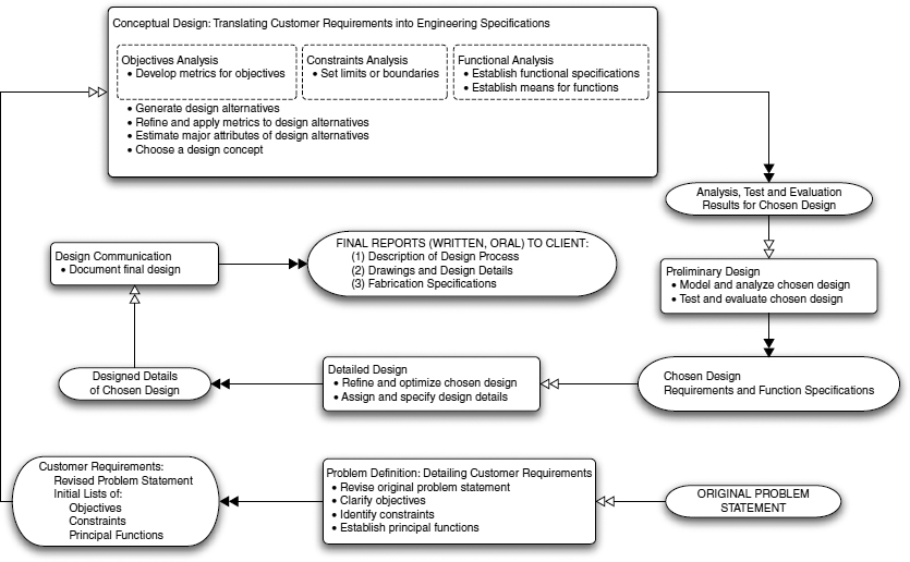
Figure 2.1 A five-stage prescriptive model of the design process, presented as a spiral to convey the idea that design is not a simple linear sequence of tasks to be done. The design stages are in rectangles, and each stage's outputs are in ovals.
Another three-stage model splits up the design process differently: Conceive, design, and implement a final design, with the context providing meanings for these three steps. These two models are simple, but they are very abstract and provide no useful advice on how to actually generate designs.
We show a more extensive prescriptive model of the design process in Figure 2.1. It has five phases, shown in boxes with rounded corners, starting with an initial problem statement and ending with final design documentation. Figure 2.1 also shows, in ovals, the output of each design phase that also serves as input to the next design phase, and it displays the links between the five stages of this design process. We can also delineate the model and its design tasks in charts that describe each phase, showing the input(s) to that phase, the design tasks to be performed, and the output(s) or product(s) of that phase that in turn work as input to the next phase:
- Problem definition: We frame the problem by delineating the customer requirements, which means clarifying the client's objectives, identifying constraints, and establishing functions before we begin conceptual design.
- During problem definition we frame the problem by clarifying objectives, identifying constraints, establishing functions, and gathering the other information needed to develop an unambiguous statement of a client's wishes, needs, and limits, that is, the customer requirements.

Input: original problem statement Tasks: revise client's problem statement clarify objectives
identify constraints
establish principal functions
Outputs: customer requirements: revised problem statement
initial list of final objectives
initial list of constraints
initial list of principal functions
- Conceptual design: We generate different concepts or schemes to achieve a client's objectives, satisfy constraints, and perform functions. Enough details (e.g., the spatial and structural relationships of the principal components) are worked out to estimate costs, weights, overall dimensions, and so on. Ladder concepts might be an extension ladder, a stepladder, or a rope ladder. We evaluate these concepts first translating the customer requirements (i.e., objectives, constraints, and functions) into engineering specifications that we use to articulate and benchmark our design.
- 2. In the conceptual design stage of the design process we translate the customer requirements into engineering specifications to generate concepts or schemes of design alternatives or feasible (i.e., acceptable) designs.

Input: customer requirements revised problem statement
initial list of final objectives
initial list of constraints
initial list of principal functions
Tasks: establish functional specifications establish means for functions
write limits or boundaries of constraints
develop metrics for objectives
generate design alternatives
refine and apply metrics to design alternatives
estimate design alternatives' major attributes
choose a design concept
Output: a chosen design analysis, test, and evaluation results for chosen design
With its focus on trade-offs between high-level objectives, conceptual design is clearly the most abstract and open-ended part of the design process. Its output may include several competing concepts. Some argue that conceptual design should produce two or more schemes since early commitment to or fixation on a single design choice may be a mistake. This tendency is so well known among designers that it has produced a saying: “Don't marry your first design idea.”
- 2. In the conceptual design stage of the design process we translate the customer requirements into engineering specifications to generate concepts or schemes of design alternatives or feasible (i.e., acceptable) designs.
- Preliminary design or embodiment of schemes: Here we flesh out our proposed concepts, that is, we embody or endow design schemes with preliminary versions of their most important attributes. We select and size the major subsystems, based on lower-level concerns that take into account the performance and operating requirements. For a stepladder, for example, we size the side rails and the steps, and perhaps decide how to fasten the steps to the side rails.
- 3. In the preliminary design phase we identify and preliminarily size/estimate the principal attributes of the chosen design concept or scheme.
Input: a chosen design specifications
Tasks: model and analyze chosen design
test and evaluate chosen design
Output: analysis, testing, evaluation of chosen design
Preliminary design is definitely more “technical”: We might do back-of-the-envelope or computer calculations. We make extensive use of rules of thumb about size, efficiency, and so on, that reflect our design experience.
- 3. In the preliminary design phase we identify and preliminarily size/estimate the principal attributes of the chosen design concept or scheme.
- Detailed design: We now articulate our final design in much greater detail, refining the choices we made in preliminary design down to specific part types and dimensions. We use detailed design knowledge and procedures expressed in specific rules, formulas, and algorithms that are found in design codes (e.g., the ASME Pressure Vessel and Piping Code, the Universal Building Code), handbooks, databases, and catalogs.
- 4. During detailed design we refine and optimize the final design and assign and fix the design details.
Input: the analyzed, tested, evaluated design Tasks: refine, optimize the chosen design assign and specify the design details
Output: proposed design and design details 
- Design communication: We now spell out and present our design process, the resulting final design, and its fabrication specifications. In practice, the designer will usually have already developed much of the documentation along the way, and this communication phase will be more about tracking and organizing prior work products than writing a “new” report from “scratch.”
- 5. Finally, during the design communication phase we document the fabrication specifications and their justification.
Input: proposed design and design details Task: document the final design Outputs: final written, oral reports to client containing: - (1) description of design process
- (2) drawings and design details
- (3) fabrication specifications

We have depicted the design process in Figure 2.1 as a spiral for several reasons. Design processes are often described as a linear sequence that seems to imply: do task 1, then do task 2, then do task 3. In practice, we actually keep completed phases and tasks in our minds as our design unfolds, and we refer back to them regularly. We may wonder while deep in a design project, “Why are we doing this?” By looking back at a project's objectives or constraints, or at a design decision we've already made, we can answer this question.
There are two other important elements that we hope the spiral depiction will help reinforce: feedback and iteration. Feedback occurs in two notable ways in the design process. First, internal feedback comes during the design process as test and evaluation results are used to verify that the design performs as intended. This feedback may come from the client and from internal customers, such as manufacturing (e.g., can it be made?) and maintenance (e.g., can it be fixed?). Second, external feedback comes after a design reaches its market and user feedback validates (or not) a successful design.
Iteration occurs when we repeatedly apply a common method or technique at different points in a design process. For example, we might write equilibrium equations for an entire structure, and then at a lower level of abstraction (i.e., on a different scale) we write equilibrium equations for structural components). Similarly, as we fix more details in a design and become less abstract, and we might review and reestablish means for our functions. Again, we always want to keep in mind the original objectives, constraints, and functions as we get closer to our final design. This may also mean that we have to do some redesign, in which case we will certainly repeat tasks such as analyzing the design or testing and evaluating the design.
Given that there are feedback loops and that we will reiterate some tasks, why didn't we include them in Figure 2.1? As important as feedback and iteration are, it is also important not to be overly distracted by these adaptive characteristics when learning about and doing design for the first time.
We now have a “checklist” we can use to ensure that we have done all of the “required” steps. Lists like this are often used by design organizations to specify and propagate approaches to design within their firms. However, we should keep in mind that this and other detailed elaborations add to our understanding of the design process only in a limited way. At the heart of the matter is our ability to model the tasks done within each phase of the design process. With this in mind, we will present some means and formal methods for doing these design tasks in Section 2.3.
2.3 INFORMING A DESIGN PROCESS
Even prescriptive descriptions of design processes can fail us because they don't tell us how to generate or create designs, or even how to do some of the tasks specified. In this section we describe some ways of thinking about design, after which we list some of the formal design methods that we explore in greater detail in later chapters. We then list some of the kinds and sources of design knowledge that informs what we do as designers, including: how we acquire information; how we analyze information and test outcomes against desired results; and how we get feedback from clients, users, and other interested parties.
2.3.1 Informing a Design Process by Thinking Strategically
Strategies are ways of thinking about a problem or situation. Effective designers have habits of thought they bring to their work that help them realize better decisions. Least commitment is one general strategy for thinking about design: Don't make decisions before you have to. This is a good habit of thought that guards against making decisions before there is a reason to make them. Premature commitments can be dangerous because we might become attached to a bad concept or we might limit ourselves to a suboptimal range of design choices. Least commitment is of particular importance in conceptual design because the consequences of any early design decision are likely to be propagated far down the line. It is generally unwise to commit to a particular concept or configuration until we are forced to because we've exhausted our information or range of choices or time available.
Decomposition, also known as divide and conquer, is another important habit of good design thinking: Break down, subdivide, or decompose larger problems into smaller subproblems. These smaller subproblems are usually easier to solve or otherwise handle. We do have to keep in mind that subproblems can interact, so we must ensure that the solutions to particular subproblems do not violate the assumptions or constraints of complementary subproblems.
2.3.2 Informing a Design Process with Formal Design Methods
Usually, when we think systematically about doing things, we can develop tools and techniques we can use. We now present a brief introduction to the formal design methods identified in the charts by introducing some of the formal tools we will use in following the design process.
Objectives trees are hierarchical lists of the client's objectives or goals for the design that branch out into tree-like structures. We build objectives trees in order to clarify and better understand a client's project statement. The objectives that designs must attain are clustered by sub-objectives and then ordered by degrees of further detail. For example, we might take an objective like “portable,” and break that down into subobjectives: “lightweight” and “small when collapsed for storage.” The highest level of abstraction of an objectives tree is the top-level design goal, derived from the client's project statement. In Chapter 4 we explain how to construct objectives trees and explore the kinds of information we learn from them.
Pairwise comparison charts (PCCs) are used to rank order our design objectives. It is helpful, for example, to know whether it is more important to the client that our ladder is “portable” or “inexpensive” in case trade-offs need to be made. A PCC is a relatively simple device in which we list the objectives as both rows and columns in a matrix or chart and then compare them on a pair-by-pair basis, proceeding in a row-by-row fashion. We use PCCs early in the design process, and they are described in Section 4.4.
Metrics are created to measure how well we achieve a design's objectives, thus allowing us to evaluate design alternatives in terms of attributes the client desires. We explain how we create metrics in Section 4.5.
Functional analysis is used to identify what a design must do. Identifying and performing functions are central to engineering design, and we will develop several approaches (e.g., black and transparent boxes, dissection, enumeration, and function–means trees) to functional analysis in Chapter 6.
The performance specification method provides support for the elaboration of the specifications that reflect, in engineering terms, how a design will function. The aim is to list solution-independent attributes and performance specifications (i.e., “hard numbers”) that specify the requirements of a design concept. We describe performance specifications (requirements) and their role in Section 6.2.
Morphological charts are used to identify the ways or means that can be used to make function(s) happen. Such “morph charts” express functions as verb–noun action pairs; the means are specific ways to use or convert energy, or to process information and/or materials. For example, if one of our ladder functions is to stabilize the user over uneven terrain, we could realize that by having adjustable feet, or by having a wide base. The morph chart provides a framework of the design space, an imaginary “space” that we can use to generate potential design alternatives for a design problem. We describe morph charts in Chapter 6.
2.3.3 Acquiring Design Knowledge to Inform a Design Process
The literature review is the classic way to find examples of prior work and determine the state of the art. We need literature reviews early on, in the framing and conceptual stages, to better understand the client, potential users, and the design problem itself. We should consider existing solutions, because there's little point or profit in reinventing the proverbial wheel. In detailed design, we may want to review available off-the-shelf parts and materials to help standardize our design and reduce fabrication costs. So at various stages we should look at the technical literature, patent listings, vendor literature, handbooks, material properties tables, and design and legal codes.
Benchmarking competitive products means evaluating the functionality and behavior of similar products already on the market. Benchmarking is often done to set a bar for a better product.
Reverse engineering or dissection is also about “seeing what's out there”: it consists of dissecting or taking apart competitive or similar products. It is often done to assess functional behavior with the aim of developing better means to accomplish the same or similar functions.
Informal interviews of potential users should be undertaken very early in a design project to assist in problem definition. While informal interviews are relatively easy to conduct, it is important to be sensitive to the time and other constraints of the interviewees by preparing for the interviews, for example, provide the interviewees with advance lists of the topics and questions, and complete a significant part of the literature research before conducting those interviews.
User surveys and questionnaires are used in market research to identify users' views of the problem space and their response to possible solutions. Market research can help clarify a design problem in its early stages, especially with open-ended questions. Later surveys can be used together with PCCs and morph charts to help select a final design.
A structured interview melds the consistency of surveys with the flexibility of informal interviews by using a previously defined set of questions that may or may not be made available to the interviewees. An interviewer can follow up a particular response and open up new areas. A structured set of questions also assures the interviewee that the interview has both purpose and focus, and it provides an agenda that ensures that key matters will be covered.
Focus groups are an expensive way to elicit the response of appropriately selected users and others to potential designs. They are not often used by student design teams because they demand considerable sophistication in psychological matters and are expensive.
Structured brainstorming by a design team can also generate ideas and insights, and in opening up new avenues for research and analysis. However, productive brainstorming is a complex activity that requires thought, preparation, and appropriate professional behavior.
2.3.4 Informing a Design Process with Analysis and Testing
We can't know whether or not a design concept might work unless we can measure outcomes, and we can't measure outcomes without having a metric or a standard against which to measure those outcomes. While metric is a general term meaning a frame or ruler for measurement, we will specifically use the term metrics to measure how well a design's objectives are achieved. We will describe how we develop metrics in Section 4.4. We will also develop another set of measurements, design specifications, to state in engineering terms the functional performance of a design. This is an extremely important topic that we will discuss in depth in Sections 6.2 and 7.3.
Experiments and testing are often used to get data, in the field or in a lab, about how well potential design actually works. Testing can run the gamut from component testing to proof-of-concept testing, to prototype development, and testing. We will say a good bit more about such testing in Chapter 11.
In many cases we don't develop or test a prototype, perhaps due to cost, size, or hazards. In such cases, we may resort to simulation in which we exercise an analytical or computer model of a proposed design to simulate its performance under a stated set of conditions. However, we can only do that if we really understand the device we're modeling and its true operating conditions. With such deep understanding, we can get useful data from simulation that will enable us to evaluate against constraints, specifications, and any applicable standards. One outstanding example of such simulation is the use of wind tunnels and related computer analyses to assess the effects of wind loading on tall buildings, on long, slender suspension bridges and, of course, airplanes.
Computer analysis is closely related to simulation and uses computer-based models, typically discipline-specific, to analyze design components in preliminary and detailed design. Such computer analyses include finite element analysis, integrated circuit modeling, failure mode analysis, and criticality analysis.
2.3.5 Getting Feedback to Inform a Design Process
We noted earlier that feedback was an intimate part of design: We use internal feedback to verify that we're solving our design problem correctly, and external feedback to validate that our design has solved the right problem.
Regularly scheduled meetings, at which the progress of the design project is tracked and discussed, may be the most important means for obtaining feedback from clients and other members of the design team.
Formal design reviews, held at specified intervals, are a standard “best practice.” We use them to update the client (and sometimes others) on the design status, typically including sufficient technical detail that the implications of the design can be explored and assessed. Design reviews involve a lot of “give and take” between the design team and its audience, and thus may seem harsh to young designers. A design team usually benefits by having to justify various technical details to clients and outside experts because its members become more aware of implicit unwarranted assumptions and errors or oversights.
In some design environments, public hearings are required by relevant civil laws or public policies in order to subject a design to public review and comment. Public hearings and meetings are increasingly the norm for major design projects (e.g., transportation or power projects), even when the client is a private entity.
We have already noted that focus groups are important sources of user input for problem definition. Such groups are also widely used to assess user reaction to designs as they near adoption and marketing.
Similarly, in industries like software design, an almost-but-not-quite-finished version of a product is released to a small number of users for beta testing. Beta tests allow designers to expose design or implementation errors and to get feedback about their product before it reaches a larger market.
2.4 CASE STUDY: DESIGN OF A STABILIZER FOR MICROLARYNGEAL SURGERY
One of the founding fathers of Harvey Mudd's design-intensive engineering program, the late Jack Alford, said that learning to design was like to learning to dance: “You have to get out on the dance floor and get your toes stepped on.” In other words, design is best learned by doing. In that context, some design tools can be learned by doing exercises, and some by seeing how others use them. We now present a design case study and begin two design examples to illustrate how engineers do conceptual design.
The case study and one of the design examples are drawn from student work done by engineering majors in their first engineering course at Harvey Mudd College, E4: Introduction to Engineering Design. Student teams are assigned the task of developing and prototyping a conceptual design of a device or system. The projects are virtually always done for nonprofits or educational institutions, and they provide HMC students with the insight that good engineering design may be done in nontraditional, noncorporate settings. The course stresses the formal design methods we present in this book.
The design project we describe was undertaken by four teams of students on behalf of Brian Wong, M.D., of the Beckman Laser Institute of the University of California Irvine. The particulars of this case study are an edited combination of results obtained by the four teams that shows how design teams thought through the design process while they were designing a device for a client. The project was concerned with laryngeal surgery.
Laryngeal, or vocal cord, surgery is often required to remove growths such as polyps or cancerous tumors. The “lead” cells of such growths must be removed accurately and completely. Patients also incur the risk of damage to their vocal cords—and so their speech—during these surgeries. In spite of many other surgical advances over recent decades, laryngeal surgery has not changed much. One change that has occurred, however, is that surgeons now access the vocal cords through the mouth, rather than by cutting open the throat. This has made it harder to insert and stabilize both optical devices and surgical instruments that cut, suck, grasp, move and suture. Surgeons must be able to control their own tremors in order make accurate and precise cuts during the procedure.
Tremor is the natural, small-scale shaking of the hand. (Watch the movement of your own fingertips as you hold your hands straight out in front of you.) In the context of laryngeal surgery, such tremors tend to be amplified as the surgeons insert and control foot-long instruments in the patient's throat.
The project began when Dr. Wong presented the following initial problem statement to the student teams:
Surgeons who perform vocal cord surgery currently use microlaryngeal instruments, which must be used at a distance of some 12–14 in. to operate on surfaces with very small structure (1–2 mm). The tremor in the surgeon's hand can become quite problematic at this scale. A mechanical system to stabilize the surgical instruments is required. The stabilization system must not compromise the visualization of the vocal cords.
The teams began by defining or framing this design problem. They talked with Dr. Wong and other physicians and did some basic library research to develop more information about laryngeal surgery. They learned that the abnormalities that were operated on were typically 1–2 mm wide, while the vocal cords themselves are approximately 0.15 mm thick. This meant that the physiological surgical tremors of the surgeon's hands had to be reduced from 0.5–3.0 mm to an acceptable tremor amplitude of 0.1 mm. They also learned that the surgeons needed to control the instruments at distances far from the patient's mouth (and vocal cords). One of the teams wrote the following revised problem statement:
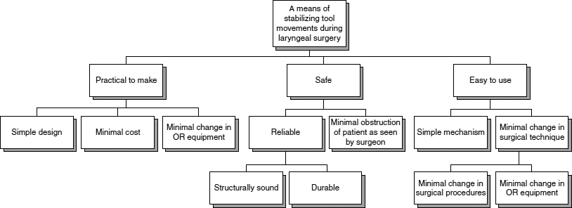
Figure 2.2 The objectives tree displaying the client's objectives and subobjectives for the microlaryngeal stabilization device whose design is presented as a case study in Section 2.5.1. This tree is developed largely from the work of one of the three teams who worked on this project. After Chan et al. (2000).
Microlaryngeal surgery seeks to correct abnormalities in the vocal cords. The abnormalities, such as tumors and cysts, are often 1–2 mm in size and are typically removed from the vocal cords, which are only 0.15 mm in size. During the operation, the surgeon must control his or her surgical instruments from a distance of 300–360 mm (12–14 in.) due to the difficulties in accessing the vocal cords. At this small scale, the physiological tremor in the surgeon's hand can be problematic. Design a solution that minimizes the effects of hand tremors in order to reduce unintentional movements at the distal end of the instrument to an amplitude of no more than 1/10 of a millimeter. The solution must not compromise visualization of the vocal cords.
Note that this revised problem statement contains more detail and also excludes an implied “mechanical” solution referenced in the original problem statement.
Continuing with problem framing, the teams listed the client's objectives for the designed stabilizing device. Objectives and subobjectives are routinely displayed in an objectives tree. One team's objectives tree for this project is displayed in Figure 2.2. Two of the objectives are that the device should minimize obstruction of the surgeon's vision, and the manufacturing cost should be minimized. The teams also developed lists of constraints, that is, the strict limits that govern acceptable designs. A constraint list for the device includes the following:
- it must be made of nontoxic materials;
- it must be made of materials that do not corrode;
- it must withstand sterilization;
- its cost must not exceed $5000;
- it must not have sharp edges;
- it must not pinch or gouge the patient; and
- it must be unbreakable during normal surgical procedures.
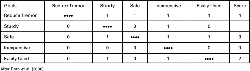
TABLE 2.1 A pairwise comparison chart created by one of the student teams to compare objectives for the microlaryngeal stabilization device. An entry “1” indicates the objective in that row is more important than that of the column in which it is entered. It shows that the reduction of the surgeon's tremor is the most important objective for this project
We see that there is an upper limit on the cost and on the device having sharp edges, among others.
Another facet of framing the problem involved rank ordering the design objectives in terms of their perceived relative importance. This ranking was done using a PCC, which is an extension of what people do when comparing two objects, one against the other. The PCC, which will be explained in detail in Section 4.3, enables each objective to be compared to every one of the other objectives, The PCC produced by one of the teams is shown in Table 2.1; it shows that reducing the surgeon's tremor is the most important objective, while cost is the least important. This ranking helped focus the team's attention, as well as seeming to accord with our intuitions.
The teams then set about establishing metrics that would enable them (later in the design process) to measure whether various designs would achieve the objectives set out for the project. The metrics for two of the objectives of Figure 2.2, along with their units and scales, are
Objective: Minimize viewing obstruction.
Units: Rating percentage of view blocked on a scale from 1 (worst) to 10 (best).
Metric: Measure the percentage of view blocked by the instrument. On a linear scale from 1 (100%) to 10 (0%), assign ratings to the percentage of view blocked.
Objective: Minimize the cost.
Units: Rating cost on a scale of 1 (worst) to 5 (best).
Metric: Determine a bill of materials. Estimate labor, overhead, and indirect costs. Calculate the total cost. On a scale from 1 (worst) to 5 (best), assign ratings to the calculated cost as follows:
| Cost ($) | Points |
| 4000–5000 | 1 |
| 3000–4000 | 2 |
| 2000–3000 | 3 |
| 1000–2000 | 4 |
| 1–1000 | 5 |
Continuing on with their conceptual design tasks, the design teams turned to functional analysis, that is, to determining what a successful design will actually do. The teams determined the specific functions that their proposed devices must perform, along with specifications, which are the engineering expressions of the performance of the functions. The teams identified the required functions by applying some of the tools that will be discussed in detail in Section 6.1, including the black box, the glass box, and the functions–means tree. One team's list of functions states that the microlaryngeal stabilizer must do the following:
- stabilize the instrument;
- move the instrument;
- stabilize the distal end of the instrument;
- reduce surgeon's muscle tension (shaking tremors) during surgery; and
- stabilize itself.
The specification for the first of these functions was written as follows:
Function: Stabilize the instrument.
Specification: This function is not achieved if the design cannot reduce the amplitude of a trembling hand to less than 0.5 mm; it is optimally achieved if it controls the amplitude of a trembling hard to make it less than 0.05 mm; and it is overly restrictive if it inhibits or disallows any instrument or hand use.
With the functions and their specifications now largely established, the design process turned to creating or generating alternative designs. One excellent way to begin creating designs is to list each of the required functions in the left-hand column of a matrix, and then list across each functional row the various means by which each function can be implemented. The resulting matrix or chart is called a morphological chart or “morph chart.” Figure 2.3 is a morph chart for the microlaryngeal stabilizer. Such morph charts effectively tell us how large a design space we are working in because each design candidate must achieve every function, no matter which of its implementations or means are used. Thus, for each of the six functions displayed in Figure 2.3, we select one of its following means to produce a possible design. As we will explain in more detail in Chapter 6, a given function's means may not necessarily connect with all of the means of all of the other functions, in which case there will be combinations that must be excluded. Still, the combinatorial effects can be daunting for designs that have many functions since each function can be implemented by several different means.
For the laryngeal stabilizer project, one design alternative positioned the surgical instrument at the end of a lever. A second design alternative had the instrument supported on a stand, moved by a system of pulleys, and supported by the stand itself. The instrument stand removes the need for surgeon to operate in a fixed position, which thus reduces tremor-inducing muscle tension. In the third design alternative, the surgeon's hands hold and move the instrument. Distal support is provided by crosswires attached directly to the laryngoscope. A forearm rest reduces the surgeon's tremor-inducing muscle tension. Figure 2.4 shows concept drawings for these three design alternatives.

Figure 2.3 A morphological chart for the microlaryngeal stabilization device showing the functions and the corresponding means or implementations for each function. Possible design solutions are assembled by selecting one means from each row. After Chan et al. (2000).
We complete the conceptual design phase of the design process by narrowing the field of possible designs and, eventually, selecting a final design. We can do this by exercising a decision or selection matrix in which we evaluate each design based on how well it achieves each of the design objectives as measured by the metrics described just above. As we will point out in Chapters 4 and 8, such decision matrices must be used with care because the numbers are often subjective, for example, some of the metrics may be qualitative assessments rather than quantitative measurements. We cannot weight or add the scores for the objectives: we can only rank them in perceived order of importance. In the present case, for example, the design that was finally chosen by the client, the crosswire support would not have the highest total value, if we had summed the scores (see Figure 2.5).
Design concepts or ideas must also be tested in meaningful ways in order to ensure that they work. One of the student design teams tested its concept by attaching a pencil lead to the end of a surgical tool and traced a predrawn square with the instrument both with and without their design being attached. As we can see from their test results, displayed in Figure 2.6, their designed device removed almost all of the tremor.
Finally, after all of the work and the selections, the design process is complete and a design can be documented and turned over to the client. In this case, one of the selected designs is being used in laryngeal surgeries and being prepared for manufacture as a medical product.
This case study has presented many of the design tools that are the main focus of this book. We have not shown the management tools used by the teams, although the design teams on this project did use them, and we have said nothing about the dynamics of each of the three design teams. These as yet unsung elements are also very important for achieving effective design results.
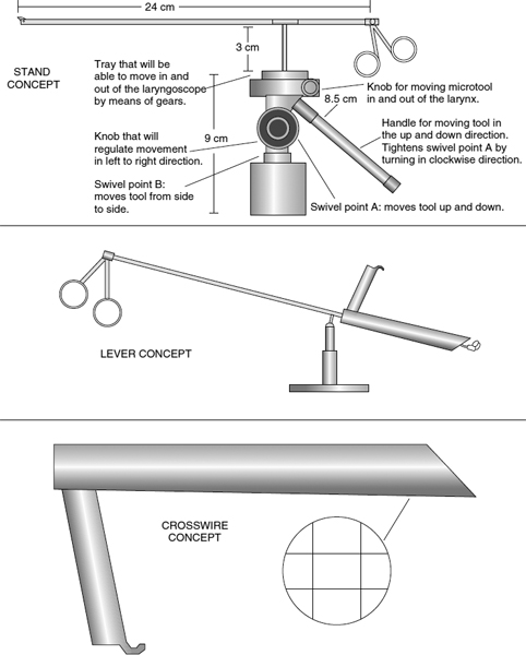
Figure 2.4 Three design alternatives produced by the student teams that worked on the microlaryngeal stabilization device for surgeons at the University of California at Irvine. Dr. Wong and his colleagues have adopted the crosswire concept for clinical trials. After Both et al. (2000), Chan et al. (2000), and Saravanos et al. (2000).

Figure 2.5 A decision or selection matrix used by one of the student teams that worked on the microlaryngeal stabilization device to select a final design. The decision matrix, whose numbers should be taken with caution, suggests which designs are preferred. After Chan et al. (2000).
2.5 ILLUSTRATIVE DESIGN EXAMPLES
We now briefly describe two illustrative examples that will be carried through the remainder of the book to illustrate the various design techniques. The first illustrative example is the design of a container for a new juice product. A summary of the juice container project is:

Figure 2.6 An example of the testing done by one student team to show that their concept successfully stabilized the surgeon's hand and reduced tremor, as demonstrated by the successful tracing of a predrawn square. After Chan et al. (2000).
Design of a container to deliver a new children's juice. This is a stylized industrial design project that highlights some of the early questions that must be addressed before a designer can apply more conventional engineering science knowledge to the problem.
Designers: Dym, Little, and Orwin LLC
Clients: American Beverage Company (ABC) and National Beverage Company (NBC)
Users: Children living both in the United States and abroad
Initial Problem Statement: Design a bottle for a new children's juice product.
The second illustrative design example is based on the work done by students in the first-year design course at Harvey Mudd College. We use their results to illustrate and further explain how formal design methods are used. In many cases, the design teams' results are displayed exactly as they presented them in their final reports at the end of the semester, without any further edits. This second illustrative example project is:
Design of an arm restraint device for children with cerebral palsy. An arm restraint was designed by a team of students in Harvey Mudd College's first-year design course.
Designers: Teams of students in HMC's first-year design class
Client: Danbury School, Claremont, California
Users: Students at Danbury School diagnosed with cerebral palsy (CP)
Abbreviated Problem Statement: Design a device to stabilize the arm of a student and counteract her involuntary, CP-induced tremors as she writes or draws.
2.6 NOTES
Section 2.1: The stepladder example derives from the first-year design course taught at Harvey Mudd College and is briefly described in Dym (1994b). The paraphrasing of Aristotle's observation is from Dym et al. (2005).
Section 2.2: As with definitions of design, there many descriptions of the design process, and many of them can be found in Cross (1994), Dym (1994a), French (1985, 1992), Pahl and Beitz (1996), and VDI (1987). Further descriptions of the tasks of design can be found in Asimow (1962), Dym and Levitt (1991), and Jones (1992). Examples of the application of conceptual design tools as problem-solving tools can be found in Schroeder (1998) for automobile evaluation and in Kaminski (1996) for college selection. The create–design–implement abstraction is also the basis for the model CDIO engineering curriculum (Crawley et al. 2007).
Section 2.3: Further elaboration of strategic thinking in design appears in Dym and Levitt (1991). More elaborate descriptions of formal design methods can be found in Cross (1989), Dym (1994a), French (1985, 1992), Pahl and Beitz (1984), and VDI (1987). Detailed descriptions of ways to acquire and process knowledge are given in Bovee, Houston, and Thill (1995), Ulrich and Eppinger (2000), and Jones (1992).
Section 2.4: The microlaryngeal stabilization device case study is detailed in Both et al. (2000), Chan et al. (2000), Feagan et al. (2000), and Saravanos et al. (2000).