
Chapter 4
Hacking a Toy to Make a Talking Puppet
In This Chapter
![]() Preparing to build your project
Preparing to build your project
![]() Bread-boarding the circuit
Bread-boarding the circuit
![]() Having fun with your puppet
Having fun with your puppet
Did you have a talking doll as a child – perhaps a Barbie who asked ‘Would you like to go shopping?’ or an action figure who declared ‘Hold your fire until I give the order’? All you had to do was pull a string in the doll’s back to hear half a dozen phrases in rotation. The trouble was that those recordings repeated over and over again, driving mad any adult within earshot. If only you could’ve made them say something different once in a while.
Well, today you can – with a little electronics. Engineers with a sense of humour even run toy-hacking workshops where you chop and change bits of toys to make them do new and surprising things. Action Man takes on a whole new character when with Barbie’s voice box he declares ‘I just love being a fashion model’. And how great to hear Barbie bark out the command ‘Mortar attack, dig in’!
In this chapter, you discover how to work with a sound synthesiser chip, an amplifier and a speaker to produce almost any sound you can imagine, while also picking up a bit about how amplification works.
You can place a sound chip in just about any object and use switches to activate sounds. For this project, we choose a hollow hand puppet of Merlin, because it lets you insert the project breadboard and switches easily (and because we’re fans of the television series). But you can use anything you like for your talking doll.
Talking about the Big Picture: Project Overview
In this chapter’s project, you create a talking hand puppet, doll or whatever else you manage to squeeze the circuit into. You can program the synthesiser chip inside the puppet with any messages you like, from ‘Cancel Doctor Who’ to ‘Bring back Doctor Who’!
The words or sounds are activated when you shake one of the puppet’s hands or press its nose. Alas, adding the electronics to the puppet makes it unsuitable for use on your hand, but you can’t have everything.
To program the sounds, you connect the board to a computer using an RS232 cable, which means that you need an old computer with an RS232 port and running the Windows XP operating system.
Using a cheap, old computer means that you can dedicate one to your electronics projects like this. You could add parallel ports to your more up-to-date computer using an expansion card or USB adaptor (which are available from stores such as Maplin or to order online - just search for ‘serial port card’ or ‘USB serial port’). To install a card you’d have to follow the manufacturer’s instructions in opening up the back of your desktop computer and inserting it into a PCI or PCI-express slot. The adaptor just plugs into a USB port but you may have to install a piece of driver software for it to work. All in all, using a cheap, old computer is much less hassle!
You can see our finished talking puppet (okay, you have to imagine the talking part) in Figure 4-1.
Here are the necessary tasks for creating your own talking toy:
1. Put together an electronic circuit containing a sound synthesiser chip, an amplifier and a speaker.
2. Connect the circuit to your computer to program the sound synthesiser with sentences, music or whatever strange sounds you’d like to play around with (a burping Barbie, anyone? Sorry, this project brings out the child in us!).
3. Place the box containing the circuit inside the puppet and connect switches in the puppet to the circuit.
After these steps, when someone presses the puppet’s hand or nose, it plays whatever you program in the sound synthesiser for that particular switch.
 Although the hand puppet we work with in this chapter may seem like a toy, it’s not intended for young children. The wires and small electronic components can be swallowed and you certainly don’t want youngsters playing with batteries.

Figure 4-1: Meet Magic Merlin.
Scoping out the schematic
You have to put together only one breadboard for this project. We present the schematic for the board in Figure 4-2.
Here’s a tour of the schematic elements:
![]() IC1 is a SpeakJet sound synthesiser model. You can connect this integrated circuit to your computer and program it to generate electrical signals by using software supplied by the manufacturer. These signals correspond to words that form sentences, sounds that create music or various cool sound effects. The software allows you to program eight sounds, each controlled by one of Pins 1–4 and 6–9 of the IC. The SpeakJet is available in the UK from Active Robots (www.active-robots.com).
IC1 is a SpeakJet sound synthesiser model. You can connect this integrated circuit to your computer and program it to generate electrical signals by using software supplied by the manufacturer. These signals correspond to words that form sentences, sounds that create music or various cool sound effects. The software allows you to program eight sounds, each controlled by one of Pins 1–4 and 6–9 of the IC. The SpeakJet is available in the UK from Active Robots (www.active-robots.com).
![]() C1 is a capacitor (something we introduce in Book II, Chapter 3) that filters noise from the +4.5V supply to IC2 (see the relevant bullet point later in this list).
C1 is a capacitor (something we introduce in Book II, Chapter 3) that filters noise from the +4.5V supply to IC2 (see the relevant bullet point later in this list).

Figure 4-2: The schematic of the talking puppet circuit.
![]() Switches S1, S2 and S3 control the voltage on Pins 2, 4 and 7 on IC1. The switches are normally open, which means that each pin is normally connected to ground. When you push one of the switches, the voltage on the corresponding pin rises to +4.5 volts (V). When you release the switch, the voltage on the pin returns to ground. Because we program the SpeakJet to trigger when the voltage on a pin changes from high (+4.5 V) to low (ground), the sound which that pin controls is triggered when you press and release the corresponding switch. We use three switches to control three sounds, because our puppet has three handy spots for placing switches.
Switches S1, S2 and S3 control the voltage on Pins 2, 4 and 7 on IC1. The switches are normally open, which means that each pin is normally connected to ground. When you push one of the switches, the voltage on the corresponding pin rises to +4.5 volts (V). When you release the switch, the voltage on the pin returns to ground. Because we program the SpeakJet to trigger when the voltage on a pin changes from high (+4.5 V) to low (ground), the sound which that pin controls is triggered when you press and release the corresponding switch. We use three switches to control three sounds, because our puppet has three handy spots for placing switches.
![]() Resistors R1, R2 and R3 limit the current running to ground when you press switches S1, S2 or S3 (see Book II, Chapter 2 for an introduction to resistors).
Resistors R1, R2 and R3 limit the current running to ground when you press switches S1, S2 or S3 (see Book II, Chapter 2 for an introduction to resistors).
![]() IC2 is a MAX232 driver/receiver chip that converts the signals from your computer. These signals aren’t generated with the correct voltage for this circuit, and so signals have to be converted so that the SpeakJet chip can use them. This chip also converts signals from the SpeakJet into signals that your computer can use.
IC2 is a MAX232 driver/receiver chip that converts the signals from your computer. These signals aren’t generated with the correct voltage for this circuit, and so signals have to be converted so that the SpeakJet chip can use them. This chip also converts signals from the SpeakJet into signals that your computer can use.
![]() C2, C3, C4 and C5 are capacitors that fill a function that the Max232 designers call charge pump capacitors. These parts are required to make the IC2 function properly.
C2, C3, C4 and C5 are capacitors that fill a function that the Max232 designers call charge pump capacitors. These parts are required to make the IC2 function properly.
![]() R6 and R7, C6 and C7 are two resistors and two capacitors, respectively, that form a low pass filter, which eliminates high-frequency noise prior to the signal reaching the amplifier.
R6 and R7, C6 and C7 are two resistors and two capacitors, respectively, that form a low pass filter, which eliminates high-frequency noise prior to the signal reaching the amplifier.
![]() C8 is a capacitor that removes any direct current (DC) offset from the output of IC1.
C8 is a capacitor that removes any direct current (DC) offset from the output of IC1.
![]() R8 is a potentiometer that controls the sound volume.
R8 is a potentiometer that controls the sound volume.
![]() IC3 is an LM386N-1 audio amplifier that takes the electrical signal generated by the SpeakJet when you push and release one of the switches in the puppet and then amplifies the electrical signal to create enough power to drive the speaker.
IC3 is an LM386N-1 audio amplifier that takes the electrical signal generated by the SpeakJet when you push and release one of the switches in the puppet and then amplifies the electrical signal to create enough power to drive the speaker.
![]() C9 is a capacitor that improves the stability of the LM386 amplifier to prevent problems such as oscillation.
C9 is a capacitor that improves the stability of the LM386 amplifier to prevent problems such as oscillation.
![]() C10 acts as a current bank for the output. This capacitor drains when sudden surges of current occur and refills with electrons when the demand for current is low.
C10 acts as a current bank for the output. This capacitor drains when sudden surges of current occur and refills with electrons when the demand for current is low.
![]() C11 is a capacitor that removes any DC offset from the output of the LM386 amplifier.
C11 is a capacitor that removes any DC offset from the output of the LM386 amplifier.
Noting some construction issues
The tactile switches that we use in this project have very tiny leads that are meant to be surface-mounted in an assembly line. Assuming that you don’t have an assembly line handy, you have to use needle-nose pliers to crimp wire around the tiny leads to hold the wires in place while you solder them.
The DB9 connector that you use has a small metal tube or cup to which you can solder each wire connection. The easiest way to solder a wire to one of these tubes is to melt some solder into the tube, reheat the tube and then insert the bare wire end into the melted solder.
When inserting electrolytic or tantalum capacitors into the breadboard, pay attention to the polarity. Inserting the capacitors the wrong way can damage the capacitors and possibly other components in your circuit. The longer lead of the capacitor is the + side. The schematic in the earlier Figure 4-2 shows you which direction to insert the capacitor. For example, the + lead of capacitor C2 goes towards Pin 1 of IC2 and the other lead goes toward Pin 3 of IC2.
In order to feed wires from the tactile switches to a location where they can be connected to the electronics box via the shortest path, we had to cut a few holes in the fabric of the puppet. Don’t worry: he didn’t feel a thing.
Perusing the parts
Your biggest shopping decision for this project is what to place the project in. The hand puppet idea is nice because it’s hollow and has a personality, as opposed to using just a plain wooden box. In theory, however, you can put the insides of the project into any object. For example, you can cut open a stuffed toy, take out the stuffing and put the project inside.
 If you take our route and choose a hand puppet, do make sure to pick one that you like with enough room to contain the electronics enclosure and with openings that allow you to place switches in the hands, face or other areas. After you choose your housing unit, shop for the following parts for the project itself (several of which we show in Figures 4-3 and 4-4):
![]() Two 33 kΩ 5% rated, 0.5W, carbon or metal film resistors (R6 and R7)
Two 33 kΩ 5% rated, 0.5W, carbon or metal film resistors (R6 and R7)
![]() Five 1 kΩ 5% rated, 0.5W, carbon or metal film resistors (R1, R2, R3, R4, R5)
Five 1 kΩ 5% rated, 0.5W, carbon or metal film resistors (R1, R2, R3, R4, R5)
![]() One 10 kΩ rotary, knob-operated, 1/2 W or 1 W rated potentiometer (R8)
One 10 kΩ rotary, knob-operated, 1/2 W or 1 W rated potentiometer (R8)
![]() One 10 Ω 5% rated, 0.5W, carbon or metal film resistor (R9)
One 10 Ω 5% rated, 0.5W, carbon or metal film resistor (R9)
![]() Two 0.01 microfarad (μF) ceramic capacitors (C6 and C7)
Two 0.01 microfarad (μF) ceramic capacitors (C6 and C7)
![]() Five 1 μF tantalum or electrolytic capacitors (C1, C2, C3, C4, C5)
Five 1 μF tantalum or electrolytic capacitors (C1, C2, C3, C4, C5)
![]() One 0.047 μF ceramic capacitor (C10)
One 0.047 μF ceramic capacitor (C10)
![]() Two 10 μF electrolytic capacitors (C8 and C9)
Two 10 μF electrolytic capacitors (C8 and C9)
![]() One 100 μF electrolytic capacitor (C11)
One 100 μF electrolytic capacitor (C11)
![]() One battery pack for three AAA batteries
One battery pack for three AAA batteries
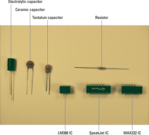
Figure 4-3: Many of the key components for the project.
We use three AAA batteries in this project to supply 4.5 V (a four-battery pack would make the supply voltage about 6 V, above the maximum supply voltage allowed for the SpeakJet IC).

Figure 4-4: Key components, part 2!
![]() One SpeakJet sound synthesiser IC1
One SpeakJet sound synthesiser IC1
The UK distributor for SpeakJet is Active Robots (www.active-robots.com).
![]() One LM386N-1 amplifier IC3
One LM386N-1 amplifier IC3
Of the many versions of the LM386 amplifier, we choose this one because it works with the supply voltage of 4.5 V used by this circuit.
![]() One MAX232 driver/receiver IC2
One MAX232 driver/receiver IC2
![]() One single-pole, single-throw (SPST) slide switch, used as the on/off switch
One single-pole, single-throw (SPST) slide switch, used as the on/off switch
![]() One 830-contact breadboard
One 830-contact breadboard
![]() Eight 2-pin terminal blocks (5.08mm pitch)
Eight 2-pin terminal blocks (5.08mm pitch)
![]() One knob (for potentiometer)
One knob (for potentiometer)
![]() One 8 Ω, 1 W speaker
One 8 Ω, 1 W speaker
![]() Three tactile switches (S1, S2, S3)
Three tactile switches (S1, S2, S3)
Many of these tactical switches are very small – as tiny as 6 mm square. We use 12 mm x 12 mm switches (part #TS6424T2602AC) made by Mountain Switch and available from Mouser (uk.mouser.com).
![]() An enclosure – large enough to take the breadboard with the speaker (see later Figure 4-15 to see how they are arranged inside)
An enclosure – large enough to take the breadboard with the speaker (see later Figure 4-15 to see how they are arranged inside)
![]() Six phono plugs
Six phono plugs
![]() Six phono jacks
Six phono jacks
![]() One DB9 female connector, solder bucket type
One DB9 female connector, solder bucket type
![]() One DB9 serial port cable
One DB9 serial port cable
![]() Four 1.3 cm 6-32 flathead screws
Four 1.3 cm 6-32 flathead screws
![]() Four 6-32 (approximately 4.7625 mm) nuts
Four 6-32 (approximately 4.7625 mm) nuts
![]() An assortment of different lengths of prestripped, short 0.7 mm diameter AWG wire
An assortment of different lengths of prestripped, short 0.7 mm diameter AWG wire
![]() An old computer with a RS232 serial port to attach the DB9 serial cable in order to program the sounds
An old computer with a RS232 serial port to attach the DB9 serial cable in order to program the sounds
Look for one running Microsoft Windows XP (we provide more information on using old computers such as this sort in Book VI, Chapter 4).
Taking Construction Step by Step
Building your talking puppet requires you to complete the following tasks:
1. Create the circuit (see the following section).
2. Drill various holes in a box and place the circuit in that box (which is the subject of ‘Making the box puppet-friendly’ later in this chapter).
3. Program the sound synthesiser (check out the later section ‘Programming fun sounds’).
4. Insert the box and switches into the puppet (flip to the later ‘Hooking up your puppet’ section).
Creating your puppet’s circuit
Gather together your breadboard and other parts to build the circuit that helps your puppet talk. Here are the steps involved:
1. Place the SpeakJet IC (IC1), the MAX232 IC (IC2), the LM386 IC (IC3) and eight terminal blocks on a breadboard, as shown in Figure 4-5.
As you can see, you connect two wires to each terminal block. The wires from these eight terminal blocks go to the battery pack, the DB9 connector, the on/off switch, the three tactile switches in the puppet, the speaker and the potentiometer.
2. Insert wires to connect the ICs and the terminal blocks to the ground bus and then insert a wire between the two ground buses to connect them to each other, as shown in Figure 4-6.
Fourteen shorter wires connect components to ground bus; the long wire on the left connects the two ground buses.
3. Insert wires to connect the ICs and the terminal blocks for the battery pack and the three tactile switches (S1, S2, S3) to the +V bus.
Figure 4-7 shows the connections.
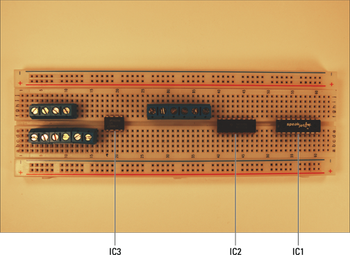
Figure 4-5: Place the ICs and terminal blocks on the breadboard.
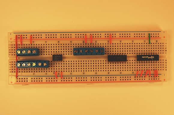
Figure 4-6: Connect the ICs and terminal blocks to ground and then connect the ground buses.

Figure 4-7: Connect components to the +V bus.
4. Insert wires to connect the ICs; terminal blocks for the potentiometer (R8) and tactile switches (S1, S2, S3); and discrete components.
Follow Figure 4-8 as a guide.

Figure 4-8: Hook up the ICs, terminal blocks (TB) and discrete components.
5. Insert discrete components on the breadboard, as shown in Figure 4-9.
 When inserting electrolytic or tantalum capacitors, be sure to check the schematic in the earlier Figure 4-2 to see where to insert the longer, positive (+) lead. The components shown in Figure 4-9 and indicated by the numbered callout comprise the following:
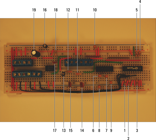
Figure 4-9: Insert resistors and capacitors on the breadboard.
1: 1 kΩ resistor R1 from IC1 Pin 7 to ground
2: 1 kΩ resistor R2 from IC1 Pin 4 to ground
3: 1 kΩ resistor R3 from IC1 Pin 2 to ground
4: 1 kΩ resistor R4 from IC1 Pin 11 to +V
5: 1 kΩ resistor R5 from IC1 Pin 12 to +V
6: 1 μF capacitor C2 from IC2 Pin 1 to Pin 3
7: 1 μF capacitor C3 from IC2 Pin 4 to Pin 5
8: 1 μF capacitor C4 from IC2 Pin 2 to ground
9: 1 μF capacitor C5 from IC2 Pin 6 to ground
10: 1 μF capacitor C1 from +V to ground
11: 33 kΩ resistor R6 from wire to IC1 Pin 18 to an open region
12: 33 kΩ resistor R7 from R6 to an open region
13: 10 μF capacitor C8 from R7 to wire to R8 terminal block
14: 0.01 μF capacitor C6 from R6 to ground
15: 0.01 μF capacitor C7 from R7 to ground
16: 10 μF capacitor C9 from IC3 Pin 7 to ground
17: 0.047 μF capacitor C10 from IC3 Pin 5 to open region
18: 10 Ω resistor R9 from C10 to ground
19: 100 μF capacitor C11 from wire to IC3 Pin 5 to wire to speaker terminal block
Clipping the wire leads on components can cause small bits of metal to fly through the air. Make sure that you wear your safety goggles when clipping leads!
6. Solder 30 cm wires to the solder cups for Pins 3, 5 and 8 of the DB9 connector.
The location of these pins is shown in Figure 4-10. Although the manufacturer prints the pin numbers next to the solder cups, you may need a magnifying glass to read the pin numbers on the connector.
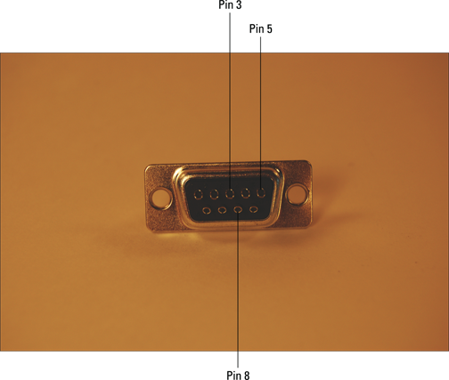
Figure 4-10: Solder cups on back of the DB9 connector.
Be sure to heed all the safety precautions about soldering that we describe in Book I, Chapter 7. For example, don’t leave your soldering iron on and unattended. And just in case a bit of solder has an air pocket and pops, wear your safety goggles!
7. Slip a 2.5 cm length of heat-shrink tubing along each wire until it covers the soldered joints.
Heat the tubing with a hair dryer to secure it and protect the joints.
Making the box puppet-friendly
In this section, we describe preparing the box so that you can insert the guts of the project into it and string wires to the puppet. This job involves some drilling, cutting and assembling.
Follow these steps to get the project box wired up:
1. Drill holes in the box for the phono jacks, potentiometer, speaker, DB9 connecter and on/off switch in appropriate locations (along the lines in Figure 4-11).
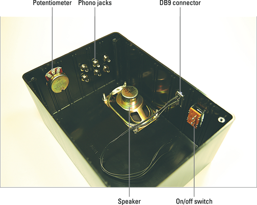
Figure 4-11: Mount components on the box.
We use a 1.3 cm drill bit for the phono jacks and an 8 mm bit for the potentiometer. To secure the speaker, we drill four holes using a 2.4 mm bit. You may need to use different bit sizes, depending on the parts you use.
Wear your safety goggles whenever you drill holes or cut wires. Also, the drill bit can bind as it goes through the plastic, causing the box to turn with the drill if it’s not properly secured. Don’t tempt fate: use a vice or other method to secure the box while you’re drilling.
2. Cut openings for the DB9 connector, on/off switch and the speaker.
We drill a pilot hole and then use a coping saw to cut the openings. The openings don’t have to be the exact shape of the part. For the DB9 connector and the switch, make the openings big enough for the body of the part to fit through. The openings can even be a little oversized as long as enough plastic is left for you to secure the part’s flange. For the speaker, cut an opening about 1 cm inside the outline of the speaker. All you need is an opening big enough to let the sound travel.
3. Insert the phono jacks, potentiometer, speaker, DB9 connector and on/off switch.
Follow Figure 4-11 as a guide.
4. Secure the phono jacks and potentiometer with the nuts provided with each part.
The outside of the box is shown in Figure 4-12.
You can secure the speaker with four 1.3 cm 6-32 (4.76 mm) flathead screws and four 6-32 (4.76 mm) nuts. Use glue on the flanges of the DB9 connector and on the on/off switch to attach them to the box.
5. Solder the black wire from the battery pack to one lug of the on/off switch and solder a 20 cm black wire to the other lug of the on/off switch.
Use Figure 4-13 to guide you.
6. Solder a 15 cm black wire to each of the two solder lugs on the speaker.
Again, Figure 4-13 shows you what you need to see.

Figure 4-12: A view from the outside.

Figure 4-13: Wires soldered to the on/off switch and speaker.
7. Solder a 20 cm wire to each of the three potentiometer lugs.
See Figure 4-14.
8. Connect 20 cm wires to each of the audio jacks and solder them.
Figure 4-14 illustrates this aspect as well.

Figure 4-14: Solder wires to connect external components to the breadboard.
9. Attach the breadboard and the battery pack to the box.
Using Velcro is the best way.
10. Cut the wires from the phono jacks, potentiometer, on/off switch, battery pack and DB9 connector.
Do so to a length that allows you to arrange the wires neatly within the enclosure.
11. Strip insulation from the ends of cut the wires, insert them in the terminal blocks and secure with wire clips, as shown in Figure 4-15.
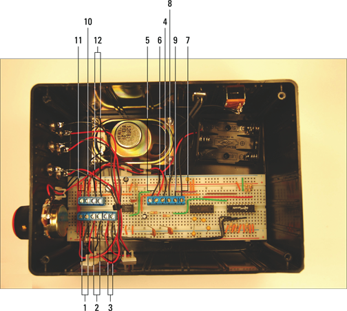
Figure 4-15: Insert wires into terminal blocks.
The components shown in Figure 4-15 and indicated by the numbered callout include:
1: Wires from left phono jack
2: Wires from centre phono jack
3: Wires from right phono jack
4: Wire from left potentiometer lug
5: Wire from centre potentiometer lug
6: Wire from right potentiometer lug
7: Wire from Pin 3 of DB9 connector
8: Wire from Pin 5 of DB9 connector
9: Wire from Pin 8 of DB9 connector
10: Red wire from battery pack
11: Black wire from on/off switch
12: Speaker wires
12. Place the on/off switch in the off position and insert batteries in the battery pack.
Secure the lid on the enclosure with the screws provided.
13. Get out your multimeter (check out Book I, Chapter 8, for how to use this tool).
Search for two contact pins on the tactile switches that are normally open (infinite resistance between the contact pins) and closed (nearly zero resistance between the two pins) when the switch is pressed.
14. Solder a 30 cm wire to each of the two pins on each tactile switch.
The result needs to look like Figure 4-16.

Figure 4-16: Solder wires to tactile switches.
15. Cut the wires from the tactile switches to the length you need to reach the jacks on the electronics enclosure after the switches and the box are in place.
Leave about an extra 10 cm of length to allow for some shifting as you stuff (sorry, place gently) the box in the puppet.
16. Unscrew the top from each phono plug, slip the top over the wire and solder each wire from the tactile switches to the centre lug of the plug.
Figure 4-17 shows you what the result looks like.
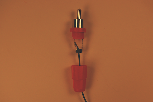
Figure 4-17: Solder wires to phono plugs.
17. Screw the covers of the phono plugs back in place and feed each tactile switch to the proper location.
We place one switch in each hand and a switch under the puppet’s nose.
18. Feed the phono jacks behind the puppet, along the lines that we show in Figure 4-18.
You may want to secure the switches in place in some fashion. We use a strip of adhesive-backed Velcro (somewhat wider than the switch) for the switch behind the nose. We stick the Velcro to the back of the switch, put the switch in place and press the adhesive back to the fabric, right under the puppet’s nose. Another idea is to use a few stitches of thread to stop the switch from moving.

Figure 4-18: Place tactile switches in the puppet.
Programming fun sounds
Even with your picture-perfect puppet and circuit, your doll can’t speak forth unless you program sounds into the sound synthesiser chip. For this task, you have to study a bit on the software provided by the manufacturer. SpeakJet doesn’t provide a lot of documentation for using the software, but we feel that the chip is the best bet for the puppet because it offers so many cool options for creating sounds.
The steps that we provide here can be only an introduction to programming the SpeakJet. The SpeakJet user guide is available from the Downloads section in its product page on the Active Robots website (www.active-robots.com/speakjet-sound-synthesizer.html). If you need more information, try the SpeakJet discussion forum at http://groups.yahoo.com/group/speakjet. You can get the PhraseALator software that you use to program the chip and its manual from the Downloads area of the www.speakjet.com website.
By using this chip and software to program SpeakJet, you can get some pretty neat functionality. For example, at your disposal is a built-in set of 72 speech elements, 43 sound effects, 3 octaves of musical notes and 12 touch tones. By mixing and matching these and controlling the pitch, rate, bend and volume settings, you can produce just about any sound, phrase or musical tones you want.
After you install the software on your computer, you can simply assign preloaded sounds to the circuit of this project, which we cover in the next set of steps. Or, you can get fancy and start programming sounds or even words of your choosing (see the later sidebar ‘Making custom sounds’). If you want to get all fancy, you need to play around for some time to suss out the software (which is beyond the scope of this book). With a little trial and error, you can get the hang of it.
We keep things simple and use the sounds that the manufacturer preloads. Here are the steps involved:
1. Open the PhraseALator software and click the Event Configuration button.
Figure 4-19 shows the SpeakJet Event Configuration that we load onto the chip. The items in the ‘Phrase# to Play’ column in this figure indicate phrases that the manufacturer preloads.

Figure 4-19: The Event Configuration screen of the PhraseALator software program.
2. Select the check boxes in the ‘Play Phrase’ column only for input events listed as Goes Low.
Doing so means that the SpeakJet activates when you first press and then release the switch. See the following minitable for help in choosing which check boxes you need to select. (The simple route is to just select all the Goes Low inputs, as shown in Figure 4-19.)
The event number in the SpeakJet software Event Configuration window doesn’t always match the pin number in the SpeakJet IC – that would be too easy. Here’s a list of event numbers and corresponding pin numbers. We wire switches to Pins 2, 4 and 7, and so we use Events 6, 4 and 2.
|
Event |
Pin |
|
0 |
9 |
|
1 |
8 |
|
2 |
7 |
|
3 |
6 |
|
4 |
4 |
|
5 |
3 |
|
6 |
2 |
|
7 |
1 |
3. Connect the box to your computer by using a serial port cable to program the SpeakJet.
Check over your circuit to make sure that no wires are loose or touch another wire – which can cause a short – before hooking them up to your computer.
4. Connect the box to your computer.
Click the Write Data to SpeakJet button in the Event Configuration screen of the SpeakJet program (as shown in Figure 4-19).
 Making custom sounds
We know that you’re the inquiring kind who wants to program custom phrases as soon as possible, and so here’s an overview of the process to get you started:
1. Open the EEPROM Editor screen in the PhraseALator software.
2. Select the check box for the Phrase# that you want to use for a custom sound.
3. Select the sounds that you want to include in a phrase in the Phrase Editor screen that opens. Be sure to check out all the words available from the library.
4. Click Done in the bottom right of the screen after you make a custom phrase. Doing so takes you back to the EEPROM Editor screen, where you can see that the selected sounds have been added to the phrase.
5. Close the EEPROM Editor screen and open the Event Configuration screen.
6. Enter the phrase number that you created in the Phrase# to Play box for one of the input #s. See the earlier minitable in this section to see how input numbers correspond to pin numbers.
7. Connect the serial cable and then click the Write Data to SpeakJet button to program the chip.
5. Finish programming the chip.
Disconnect the box with the electronics from the computer.
Hooking up your puppet
No doubt you’re dying to hear your puppet have its say, and so follow these steps to bring your newly loquacious friend to life:
1. Plug the phono plugs from one of the tactile switches into the box and press the switch, adjusting the potentiometer to get the sound level right.
2. Unplug the phono plugs and insert the electronics box in the puppet, taking care not to move the tactile switches out of position.
3. Insert each phono plug in a phono jack and tuck the wires out of sight, as shown in Figure 4-20.

Figure 4-20: The electronics concealed in the puppet.
Playing with Your Puppet
To operate your puppet, press a hand or nose and listen to the words of wisdom flow. If something doesn’t work, here are two obvious problems to address:
![]() Check that all the batteries are fresh, tightly inserted in the battery pack and all facing the right direction.
Check that all the batteries are fresh, tightly inserted in the battery pack and all facing the right direction.
![]() Check to see that no wires or components have come loose.
Check to see that no wires or components have come loose.
Adding sound to objects has endless potential, as manufacturers of stuffed toys and dolls have discovered. If you like this project, you can vary it or take it further, as follows:
![]() Use a different puppet, stuffed animal or plastic toy.
Use a different puppet, stuffed animal or plastic toy.
![]() Create a music box that plays when you press a switch.
Create a music box that plays when you press a switch.
![]() Add more switches for people to push. You can use up to eight of the event pins for sound.
Add more switches for people to push. You can use up to eight of the event pins for sound.
![]() Add light to sound. For example, you may want to put a light on your doll’s head that illuminates every time it speaks. See Book II, Chapter 5, for ideas about working with LEDs.
Add light to sound. For example, you may want to put a light on your doll’s head that illuminates every time it speaks. See Book II, Chapter 5, for ideas about working with LEDs.
If you want to program the SpeakJet only once, you don’t need to keep the MAX232 with your project. Instead, you can move the SpeakJet to a smaller breadboard, which allows you to fit the board into a smaller puppet or toy.