
Chapter 3
Making Light Dance to the Music
In This Chapter
![]() Taking a peek at the project
Taking a peek at the project
![]() Creating the circuit
Creating the circuit
![]() Lighting up to music
Lighting up to music
No doubt you’ve seen the various lights that change with the mood of the music at a disco, maybe in a school hall or at a wedding. One of the lights reacts to the sound from the record, flashing with the beat, subsiding in the quieter passages and so on.
In this chapter, we combine light and sound electronics to build a light that works in a similar way, but which you can use with any kind of music (you don’t have to drag your 1970s’ flares from the back of the wardrobe, unless you really want to). We show you how to set up two rows of lights that illuminate to different frequencies of sound. When you put on a fast, loud or heavily accented piece of music – say, swing or reggae – the lights dance all around. Every piece of music has its own, unique effect.
We arrange the lights like notes on a music staff, but you can put them in any arrangement you like. By working through this fun project, you get to know more about frequency filters, operational amplifiers and how music can light up the dance floor.
Illuminating the Big Picture: Project Overview
In this chapter, you create a display of light-emitting diodes (LEDs) that light up in response to high- or low-frequency sounds. You can see the LED musical notes arrangement in the finished display in Figure 3-1.
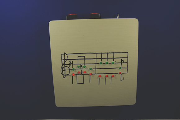
Figure 3-1: The final product: Dance to the Music!
Here’s an overview of what you’re going to be up to in the Dance to the Music project:
1. Put together an electronic circuit to turn on the LEDs in response to sounds – half the LEDs flash to high-frequency sounds and the other half flash to low-frequency sounds.
2. Create a template for the musical notes, which you place on a wooden box and into which you drill holes for the LEDs.
3. Wire two groups of LEDs and resistors.
4. Apply the juice (in other words, pop in the batteries and flip the switch) and then play some music; the circuit sends current to each group of LEDs in response to the sound.
5. Turn up the volume, check out what each of your CDs does to the lights and enjoy the show!
Scoping out the schematic
Music and light don’t just happen: you have to start with a plan – or in this case, a schematic. You’re going to put together one large breadboard and two LED arrays for this project.
Take a look at the schematic for the breadboard in Figure 3-2.

Figure 3-2: The schematic for your Dance to the Music project.
To make your musical score light up in response to the music, you need to create a circuit that uses a microphone, as well as two operational amplifier integrated circuits (ICs; check out Book III, Chapter 1 for details) in combination with resistors, capacitors and transistors (which we describe in Book II, Chapters 2, 3, and 6, respectively). Working together, they control which group of LEDs lights up to a particular frequency of music.
Here is a tour of the schematic elements that you use to control your project:
![]() An electret microphone transforms sound into electrical signals.
An electret microphone transforms sound into electrical signals.
![]() R1 connects the microphone to positive voltage and supplies about 4.5 volts (V) required by the microphone to function.
R1 connects the microphone to positive voltage and supplies about 4.5 volts (V) required by the microphone to function.
![]() C1 and C4 are capacitors that block the direct current (DC) voltage on the input signal and allow the alternating current (AC) signal to pass.
C1 and C4 are capacitors that block the direct current (DC) voltage on the input signal and allow the alternating current (AC) signal to pass.
The circuit splits between capacitors C1 and C4: the signal processed by the upper half of the circuit powers the LEDs blinking in response to high-frequency sound; the signal flowing through the lower half of the circuit powers the LEDs blinking in response to low-frequency sound.
![]() IC1 is an operational amplifier (op amp) that amplifies the signal from the microphone. The IC contains two op amps; one half of IC1 is used in the upper circuit and one half in the lower circuit.
IC1 is an operational amplifier (op amp) that amplifies the signal from the microphone. The IC contains two op amps; one half of IC1 is used in the upper circuit and one half in the lower circuit.
![]() R2 and R5 in the upper circuit and R19 and R22 in the lower circuit set the gain for each side of IC1. R5 is 50 times R2, and so a signal processed by the op amp is amplified approximately 50 times. R5 is 50 times R2, and R22 is 50 times R19.
R2 and R5 in the upper circuit and R19 and R22 in the lower circuit set the gain for each side of IC1. R5 is 50 times R2, and so a signal processed by the op amp is amplified approximately 50 times. R5 is 50 times R2, and R22 is 50 times R19.
 Gain is the amplitude of the voltage out divided by the amplitude of the voltage in: in other words, how much more juice goes out than comes in.
![]() R3, R4 and R6 in the upper circuit and R20, R21 and R23 in the lower circuit provide a DC bias to the op amp that allows the full AC signal to be amplified. If these resistors weren’t present, the portion of the AC signal coming into the op amp with voltage less than 0 V would be lost.
R3, R4 and R6 in the upper circuit and R20, R21 and R23 in the lower circuit provide a DC bias to the op amp that allows the full AC signal to be amplified. If these resistors weren’t present, the portion of the AC signal coming into the op amp with voltage less than 0 V would be lost.
Bias involves applying voltage that’s above ground to a portion of the circuit to amplify the positive and negative sides of a signal. Without DC bias, you lose part of the signal.
![]() C2 and C5 remove any DC bias from the signal coming out of the op amps.
C2 and C5 remove any DC bias from the signal coming out of the op amps.
![]() R7 and R24 are potentiometers that allow you to adjust the sensitivity of the circuit in relation to the music’s volume.
R7 and R24 are potentiometers that allow you to adjust the sensitivity of the circuit in relation to the music’s volume.
![]() C3 and R8 function as a high pass filter and R25 and C6 function as a low pass filter. These filters are what make higher-frequency sounds light up LEDs 1–8 and lower-frequency sounds light up LEDs 9–16. For details, see the nearby sidebar ‘Just passing through: Filters’.
C3 and R8 function as a high pass filter and R25 and C6 function as a low pass filter. These filters are what make higher-frequency sounds light up LEDs 1–8 and lower-frequency sounds light up LEDs 9–16. For details, see the nearby sidebar ‘Just passing through: Filters’.
 Just passing through: Filters
The portion of the circuit made up of C3 and R8 is an RC high pass filter. With this filter, signals above a certain frequency – determined by the value of C3 and R8 – pass through more easily than signals below that frequency. The strength of signals below this key frequency is therefore reduced. This type of filter is made up of the capacitor in line with the signal path and the resistor between the output of the signal and ground.
Correspondingly, the portion of the circuit made up of R25 and C6 is an RC low pass filter. Here, signals below a certain frequency – determined by the value of R25 and C6 – pass through more easily than signals above that frequency. The strength of signals above this key frequency are reduced. This type of filter has the resistor in line with the signal path and the capacitor between the output of the resistor and ground.
For both types of filters, increasing the value of either (or both) the resistor or capacitor lowers the value of the key frequency. Lowering the value of either (or both) the resistor or capacitor increases the value of the key frequency.
![]() IC2 is an op amp that amplifies the signal that passes through the filter. The IC contains two op amps; one half of IC2 is used in the upper circuit and one half of IC2 in the lower circuit.
IC2 is an op amp that amplifies the signal that passes through the filter. The IC contains two op amps; one half of IC2 is used in the upper circuit and one half of IC2 in the lower circuit.
![]() R9 and R10 in the upper circuit and R26 and R27 in the lower circuit set the gain of the op amp. R10 is 200 times R9, and so a signal processed by the op amp is amplified approximately 200 times. R10 is 200 times R9, and R27 is 200 times R26.
R9 and R10 in the upper circuit and R26 and R27 in the lower circuit set the gain of the op amp. R10 is 200 times R9, and so a signal processed by the op amp is amplified approximately 200 times. R10 is 200 times R9, and R27 is 200 times R26.
![]() Q1, Q2, Q3 and Q4 in the upper circuit and Q5, Q6, Q7 and Q8 in the lower circuit are 2N3904 transistors whose bases are connected to the output of the op amps in IC2. When the output of the op amp reaches about 0.7 V, the transistors turn on and current flows through the LEDs.
Q1, Q2, Q3 and Q4 in the upper circuit and Q5, Q6, Q7 and Q8 in the lower circuit are 2N3904 transistors whose bases are connected to the output of the op amps in IC2. When the output of the op amp reaches about 0.7 V, the transistors turn on and current flows through the LEDs.
The circuit doesn’t mean a thing if you don’t set up the lights for it to control, which is where the two groups of LEDs and resistors come in. They include:
• LED1–LED8 to light the display for the high-frequency circuit and LED9–LED18 to light the display for the low-frequency circuit.
• R11–R18 in the upper circuit and R28–R35 in the lower circuit are resistors, which in series with the LEDs limit the current running through the LEDs to approximately 10 milliamps.
Following some wiring tips
Behind the musical score we drew on the box that holds the circuit, there are a lot of resistors and LED leads soldered together. To make sure that leads that get bent and touch don’t cause a short circuit, you need to protect them. Instead of electrical tape, we suggest that you use liquid electrical tape to coat the exposed leads.
Wires run between the circuit board resting on the bottom of the box and the LEDs that you insert in the top of the box. Be sure to cut your wires long enough so that when you open the box (which moves the LEDs in the top farther away from the circuit in the bottom of the box) you don’t rip out the wires. Also be careful that you leave room to tuck those long wires inside the box when closed so that they don’t poke out the sides or get caught in the hinges. Stranded wires work better than solid wires because they’re more flexible.
Perusing the parts
You can purchase all the electronic parts that you need to build the circuit and assemble the box containing the LEDs at your nearest electronics shop or through an online vendor.
The circuit that transforms music into your dancing light show involves the following parts, several of which are shown in Figure 3-3:
![]() One 2.2 kΩ (kohm) 5% 1/4 W carbon or metal film resistor (R1)
One 2.2 kΩ (kohm) 5% 1/4 W carbon or metal film resistor (R1)
![]() Eight 220 Ω 5% 1/4 W carbon or metal film resistors (R11–R14, R28–R31)
Eight 220 Ω 5% 1/4 W carbon or metal film resistors (R11–R14, R28–R31)
![]() Eight 100 Ω 5% 1/4 W carbon or metal film resistors (R15–R18, R32–R35)
Eight 100 Ω 5% 1/4 W carbon or metal film resistors (R15–R18, R32–R35)
![]() Two 10 kΩ panel-mounting D-shaped shaft, rotary-type potentiometers (R7, R24)
Two 10 kΩ panel-mounting D-shaped shaft, rotary-type potentiometers (R7, R24)
![]() Four 47 kΩ 1% 1/4 W carbon or metal film resistors (R3, R4, R20, R21)
Four 47 kΩ 1% 1/4 W carbon or metal film resistors (R3, R4, R20, R21)
![]() Two 100 kΩ 1% 1/4 W carbon or metal film resistors (R5, R22)
Two 100 kΩ 1% 1/4 W carbon or metal film resistors (R5, R22)
![]() Two 2 kΩ 1% 1/4 W carbon or metal film resistors (R2, R19)
Two 2 kΩ 1% 1/4 W carbon or metal film resistors (R2, R19)
![]() Three 5 kΩ 1% 1/4 W carbon or metal film resistors (R6, R8, R23)
Three 5 kΩ 1% 1/4 W carbon or metal film resistors (R6, R8, R23)
![]() Two 1 kΩ 1% 1/4 W carbon or metal film resistors (R9, R26)
Two 1 kΩ 1% 1/4 W carbon or metal film resistors (R9, R26)
![]() Two 220 kΩ 1% 1/4 W carbon or metal film resistors (R10, R27)
Two 220 kΩ 1% 1/4 W carbon or metal film resistors (R10, R27)
![]() One 10 kΩ resistor (R25)
One 10 kΩ resistor (R25)
![]() One 0.001 microfarad (μF) ceramic capacitor (C3)
One 0.001 microfarad (μF) ceramic capacitor (C3)
![]() Two 0.1 μF ceramic capacitors (C1, C4, C6)
Two 0.1 μF ceramic capacitors (C1, C4, C6)
![]() Two 10 μF electrolytic capacitors (C2, C5)
Two 10 μF electrolytic capacitors (C2, C5)
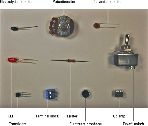
Figure 3-3: Important pieces of the Dance to the Music project.
![]() Eight green size 5mm LEDs (LED1–LED8)
Eight green size 5mm LEDs (LED1–LED8)
![]() Eight red or orange size 5mm LEDs (LED9–LED16)
Eight red or orange size 5mm LEDs (LED9–LED16)
![]() Two LM358 op amps (IC1 and IC2)
Two LM358 op amps (IC1 and IC2)
![]() One electret microphone
One electret microphone
 We use the Horn part #EM9745 electret microphone (available from Digikey at
 www.digikey.co.uk) for two reasons: high sensitivity and a reasonable size for easy handling. You can use other electret microphones, though; plenty are available to choose from online.
![]() Two 830-contact breadboards
Two 830-contact breadboards
![]() One 4-AA battery pack with snap connector
One 4-AA battery pack with snap connector
![]() Eleven 2-pin terminal blocks (5.08mm pitch)
Eleven 2-pin terminal blocks (5.08mm pitch)
![]() Two knobs (for the potentiometer)
Two knobs (for the potentiometer)
![]() Eight 2N3904 transistors (Q1–Q8)
Eight 2N3904 transistors (Q1–Q8)
![]() One panel mount SPST toggle switch
One panel mount SPST toggle switch
![]() A wooden box
A wooden box
You may find one at a local craft supply shop that’s just the right size.
![]() A metre of black 20 AWG wire
A metre of black 20 AWG wire
![]() A metre of red 20 AWG wire
A metre of red 20 AWG wire
Taking Construction Step by Step
To make the lights dance to the music, you have a few general tasks to perform:
1. Build the circuit that makes the whole circuit run (see the following section).
2. Assemble the lights on the surface of the wooden box in which you place the circuit (the subject of ‘Using LEDs to create the lights’ later in this chapter).
3. Attach knobs, an on/off switch, a microphone, potentiometers and a speaker to the box. Insert the breadboard containing the circuit in the box and connect up everything (check out the later ‘Adding the rest of the gubbins’ section for details).
Building the circuit
Time to go one-on-one with your breadboard. Grab your schematic (from the earlier Figure 3-2), tape it to the wall and get going.
Here are the steps involved in building the circuit:
1. Place the two LM385 ICs (IC1 and IC2) and 11 terminal blocks on the breadboard, as shown in Figure 3-4.
As you can see, each terminal block has connections for two wires. Here’s what the wires from each block are connected to:
• Wires from one of the terminal blocks on the right side of Figure 3-4 go to the battery pack.
• Wires from the other terminal block on the right go to the microphone.
• Wires from the terminal blocks in the centre go to the potentiometers.
• Wires from the terminal blocks on the left side of the breadboard go to the LEDs.
2. Place the eight 2N3904 (Q1–Q8) transistors on the breadboard, as shown in Figure 3-4.
Insert each transistor lead into a separate breadboard row with the collector lead to the left side (see Figure 3-4), the base lead in the centre and the emitter lead to the right. The pin designations of the 2N3904 transistors are shown in Figure 3-5.
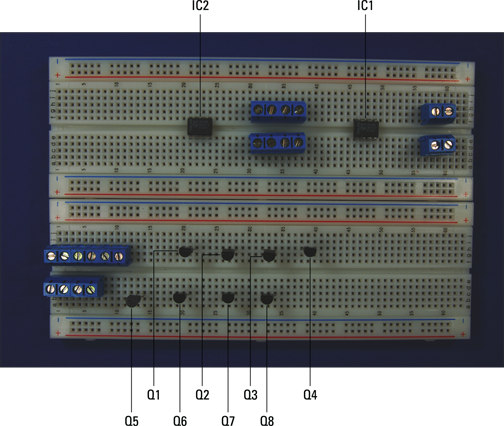
Figure 3-4: Place the LM385 ICs, 2N3904 transistors and terminal blocks.

Figure 3-5: The 2N3904 transistor pinout.
3. Insert wires to connect the ICs, the battery pack terminal block, the microphone terminal block and the potentiometer terminal blocks to the ground bus. Then insert wires between the ground buses to connect them to each other, as shown in Figure 3-6.
The ground buses are designated by a negative (–) sign on this breadboard.
4. Insert wires to connect the ICs, the battery terminal block and one of the LED terminal blocks to the +V bus. Then insert wires between the +V buses to connect them, as shown in Figure 3-7.
The +V buses are designated by a + sign on this breadboard.

Figure 3-6: Shorter wires connect components to the ground bus; the two long wires on the right connect the ground buses.
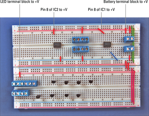
Figure 3-7: Connect components to the +V bus.
5. Insert wires to connect the ICs, terminal blocks and discrete components.
Figure 3-8 shows you the details.
6. Insert wires to connect IC2 to the transistors and the base pins of the transistors to each other.
We show you how in Figure 3-9.
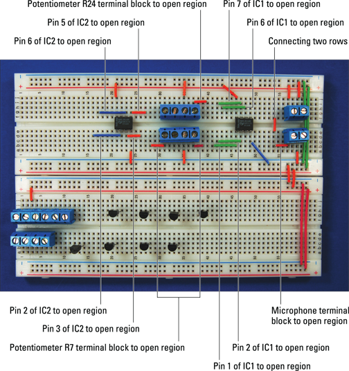
Figure 3-8: Hook up the IC, terminal blocks and discrete components.

Figure 3-9: Connect IC2 to transistors.
7. Insert three 0.1 μF capacitors (C1, C4 and C6), two 10 μF capacitors (C2 and C5) and one 0.001 μF capacitor (C3) on the breadboard, as shown in Figure 3-10.
Use the schematic in the earlier Figure 3-2 and the photo in Figure 3-10 to place each component correctly. For example, the schematic shows that the + side of C2 is connected to Pin 1 of IC1 and that the other side of C2 is connected to potentiometer R7. Therefore, you insert the long lead of C2 in the same row as the wire connected to Pin 1 of IC1 and the short lead in the same row as the wire connected to the terminal block for potentiometer R7.
Be sure to insert the electrolytic capacitors the correct way around for safety reasons (see Book VIII, Chapter 4). The caps have the negative pin marked on them.
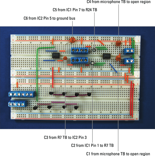
Figure 3-10: Insert capacitors into the breadboard.
8. Insert eight 100 Ω resistors (R15–R18, R32–R35) from the emitter pins of each transistor to the ground bus.
Let Figure 3-11 be your guide.

Figure 3-11: Insert resistors onto the breadboard.
9. Insert more resistors as follows (see Figure 3-12):
• One 2.2 kΩ resistor (R1)
• One 2 kΩ resistor (R2)
• Two 47 kΩ resistors (R3 and R4)
• One 100 kΩ resistor (R5)
• Two 5 kΩ resistors (R6 and R8)
• One 1 kΩ resistor (R9)
• One 220 kΩ resistor (R10) on the breadboard
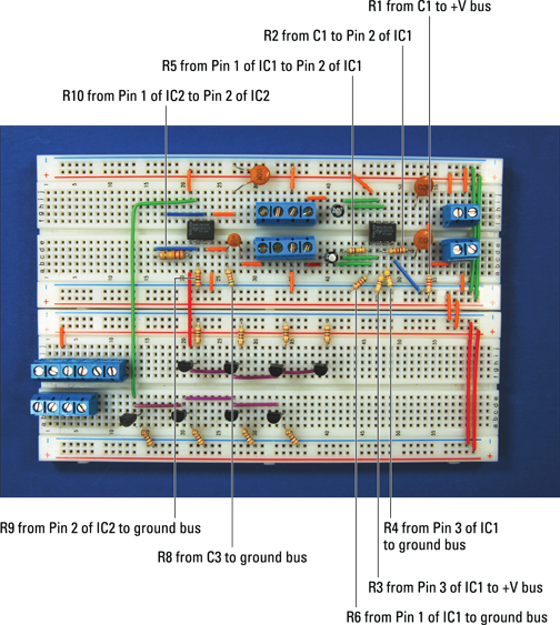
Figure 3-12: Insert more resistors onto the breadboard.
10. Insert the other resistors (as shown in Figure 3-13):
• One 2 kΩ resistor (R19)
• Two 47 kΩ resistors (R20 and R21)
• One 100 kΩ resistor (R22)
• One 5 kΩ resistor (R23)
• One 1 kΩ resistor (R26)
• One 10 kΩ resistor (R25)
• One 220 kΩ resistor (R27) on the breadboard
11. Insert wires to connect the collector pins of the transistors to the terminal blocks.
Follow the photo in Figure 3-14.
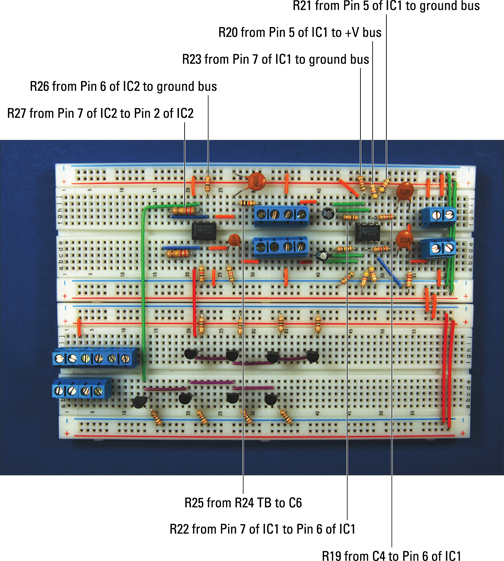
Figure 3-13: Insert the remaining resistors onto the breadboard.
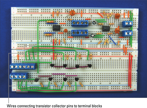
Figure 3-14: Connect the collector pins of the transistor to terminal blocks.
Using LEDs to create the lights
The brains of the circuit that you create in the preceding section exist to make the light display work. You can now assemble those lights to create your Dance to the Music display:
1. Select a series of musical notes.
Use eight high notes and eight low notes.
2. Draw a musical staff on the top of the wooden box in pencil and then draw a dot for the spot where each LED is to go.
See Figure 3-15 for help if you’re not musical!
3. Drill test holes in a piece of scrap wood to determine the size of drill bit that you need to use to give a close press-in fit for the LEDs.
We used a 5 mm drill bit.
4. Drill holes for the LEDs.
Use the locations you mark in Step 3.
5. Draw the musical notes and staff on the wooden box.
Use a permanent marker or paint brush.
6. Insert LEDs in the drilled holes.
Figure 3-15 shows the box at this stage.
7. Attach resistors between the pairs of LEDs, as shown in Figure 3-16.
Connect the 220 Ω R11–R14 and R28–31 resistors to the short lead on one LED of each pair (four pairs of each colour) and to the long lead on the other LED of the pair.
8. Solder the resistors to the leads and clip the leads just above the solder joint.
Clip only the leads to which you’ve soldered resistors. Figure 3-16 shows how the LEDs and resistors look at this point. Figure 3-17 shows a close-up to help you see the soldering more clearly.

Figure 3-15: A bit of a favourite song created with a marker and LEDs.

Figure 3-16: Resistors soldered and leads clipped.
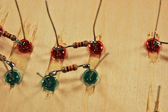
Figure 3-17: A close-up of the soldering job.
 Be sure to heed all the safety precautions about soldering that we provide in Book 1, Chapter 7. For example, don’t leave your soldering iron on if you have to step away to accept a pizza delivery. And just in case a bit of solder has an air pocket that may cause it to pop, wear your safety goggles whenever you solder or clip leads and wires.
9. Connect and solder short lengths of 20 AWG red wire between the remaining long LED leads.
Then attach a 30 cm piece of 20 AWG red wire to the remaining long lead of the first LED pair, as shown in Figure 3-18.
These wires are the +V bus for the LED arrays; you attach the 30 cm wire to a terminal block to supply voltage to the bus.
10. Clip the LED leads just above the solder joint.
Clip only the leads to which you’ve soldered the red wires; you need the remaining leads in the next step.
11. Connect and solder a 30 cm length of 20 AWG black wire to the remaining short LED lead on each pair of LEDs, as shown in Figure 3-19.
You connect each of these eight wires to a terminal block. Figure 3-20 shows these connections in close-up.

Figure 3-18: Red wires forming the +V bus for the LED arrays.
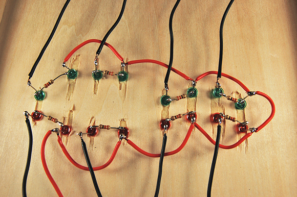
Figure 3-19: Black wires to connect each pair of LEDs to terminal blocks.

Figure 3-20: A close-up of all the connections.
12. Clip the LED leads just above the solder joint.
Make sure that the LED leads and solder joints don’t touch each other. Coat them with liquid electrical tape to help prevent any shorts that can occur if you bend or push the wires together.
Adding the rest of the gubbins
After you’ve taken care of the circuit and LEDs (in the two preceding sections), you still have a lot of other bits and pieces sitting on your workbench, such as the microphone, potentiometers, a switch and so on. You need to assemble these parts before your project can make the music dance:
1. Solder a 30 cm black wire to the microphone ground contact and a 30 cm red wire to the microphone +V contact.
Figure 3-21 identifies the microphone contacts.
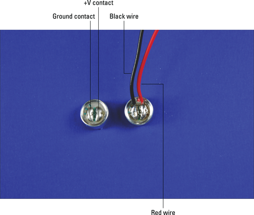
Figure 3-21: Solder wires to the microphone.
2. Drill holes in the box where you plan to insert the microphone and on/off switch.
We put the potentiometers and on/off switch on one side of the box and the microphone on another side, but the placement is up to you. Choose a drill bit size for the microphone hole so that the microphone neatly passes through it. Figure 3-22 shows you where we place these components.
Make sure that you use safety goggles when drilling and clamp the box to your worktable!
3. Slip the shaft of the on/off switch through the drilled hole.
Secure with the nut provided.
4. Slip the shaft of the potentiometers through the drilled holes.
Secure with the nuts provided.
5. Slip a knob over the shaft of each potentiometer.
Tighten with the set screw provided.
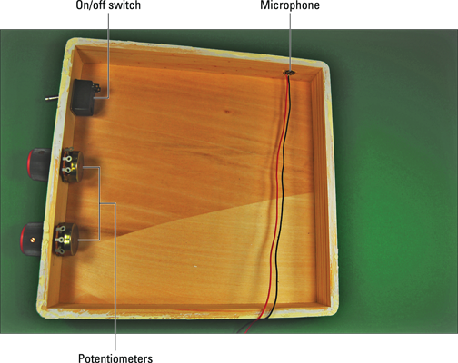
Figure 3-22: Box with on/off switch, potentiometers and microphone in place.
The tread on potentiometers is about 6 mm long, and so if the wall of your wooden box is 6 mm thick you can’t use the nut to secure the potentiometer. Instead, check to make sure that the potentiometer shaft extends far enough beyond the box to allow the knob set screw to tighten on the shaft. If the shaft extends far enough, glue the face of the potentiometer to the box, making sure that you don’t get any glue on the rotating shaft of the potentiometer. If the shaft doesn’t protrude quite enough, use a small chisel to remove some wood on the inside of the box to let the potentiometer shaft extend a little farther before you glue.
6. Slip the microphone into its drilled hole with a press fit.
Figure 3-22 shows the on/off switch, potentiometers and microphone in place in the box.
7. Solder 30 cm black wires to each of the three potentiometer lugs.
Figure 3-23 shows you how.
8. Solder the black wire from the battery pack to one lug of the on/off switch and solder a 30 cm black wire to the remaining lug of the on/off switch.
Figure 3-23 shows the switch after the wires are soldered.
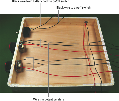
Figure 3-23: Wires soldered to the on/off switch and the potentiometers.
9. Attach Velcro to the breadboard and the box.
Secure the breadboard in the box.
10. Attach Velcro to the battery pack and the box.
Secure the battery pack in the box.
11. Insert the wires from the LEDs, battery pack and on/off switch to the terminal blocks on the breadboard, as shown in Figure 3-24.
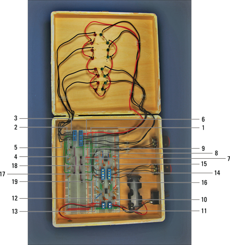
Figure 3-24: LEDs, battery pack and on/off switch connected to the breadboard.
Use the following as a key to the numbered callouts in Figure 3-24:
1: Red wire from LED +V bus
2–5: Wires from pair of red LEDs
6–9: Wires from pair of green LEDs
10: Red wire from battery pack
11: Black wire from on/off switch
12: Red wire from microphone
13: Black wire from microphone
14 and 17: Wires from right potentiometer lug
15 and 18: Wires from centre potentiometer lug
16 and 19: Wires from left potentiometer lug
12. Cut each wire as you insert them to the length needed to reach the assigned terminal block, and strip the insulation from the end of the wire.
Secure the wires with wire clips.
Trying Out Your Dance to the Music Display
Now you can get the project up and running and see whether you think it’s as much fun as we do.
You can use any sort of music you like, but we find that music with lots of instruments – such as a swing band with lots of brass – works best. Also, music with an upbeat tempo moves along and gets the lights switching on and off faster, which makes the effect better. Ella Fitzgerald singing ‘Take the A Train’ works well. (Ask your parents; they may know it!)
Here are the simple steps to get this project going:
1. Pop the batteries into the battery pack.
2. Flip the on/off switch to on.
3. Put on some music.
That’s it! Watch the lights go on and off in response to the high and low frequencies in the music. You adjust the sensitivity of the LEDs by turning the potentiometers.
Here are the obvious things to check out if you’re having a problem:
![]() Check that all the batteries are fresh and tight in the battery pack and that they all face the right direction.
Check that all the batteries are fresh and tight in the battery pack and that they all face the right direction.
![]() If one or two LEDs aren’t working, replace them.
If one or two LEDs aren’t working, replace them.
![]() If two LEDs in series with each other aren’t functioning, you may have reversed the long and short leads of the LEDs; if so, just replace that pair of LEDs.
If two LEDs in series with each other aren’t functioning, you may have reversed the long and short leads of the LEDs; if so, just replace that pair of LEDs.
![]() You’re playing Brahms’s ‘Lullaby’ or something similar, which doesn’t light up a single LED. Switch to Motörhead’s ‘Ace of Spades’ or Sly and the Family Stone’s ‘Dance to the Music’.
You’re playing Brahms’s ‘Lullaby’ or something similar, which doesn’t light up a single LED. Switch to Motörhead’s ‘Ace of Spades’ or Sly and the Family Stone’s ‘Dance to the Music’.
By now, you’re probably jumping around the living room, playing every CD you have to see what they do to the lights and wanting more, more, more. Here are a few different ways to take this project further:
![]() You can change from a musical staff and notes to any kind of shape you want to define with your LEDs. You can have two stars or a sun and moon, for example.
You can change from a musical staff and notes to any kind of shape you want to define with your LEDs. You can have two stars or a sun and moon, for example.
![]() You can use a band pass filter to add more layers of frequency. For example, between your high pass filter and low pass filter (see the earlier sidebar ‘Just passing through: Filters’), you add two more band pass filters to hit intermediate frequencies and have four sets of LEDs going off in response to music.
You can use a band pass filter to add more layers of frequency. For example, between your high pass filter and low pass filter (see the earlier sidebar ‘Just passing through: Filters’), you add two more band pass filters to hit intermediate frequencies and have four sets of LEDs going off in response to music.
![]() You can miniaturise your circuit to pin it on your shirt or take it with you to parties. You can get a smaller circuit by using smaller LEDs (for example, replacing the 5mm LEDs with 3mm LEDs). Or you can use a different method of building the circuit called a dead bug circuit. Imagine an IC turned on its back with its little prongs sticking up in the air, and you get an idea of what we mean. This method doesn’t involve a breadboard but makes a connection directly to the LED.
You can miniaturise your circuit to pin it on your shirt or take it with you to parties. You can get a smaller circuit by using smaller LEDs (for example, replacing the 5mm LEDs with 3mm LEDs). Or you can use a different method of building the circuit called a dead bug circuit. Imagine an IC turned on its back with its little prongs sticking up in the air, and you get an idea of what we mean. This method doesn’t involve a breadboard but makes a connection directly to the LED.