
Chapter 2
Unearthing Hidden Treasure with a Handy Metal Detector
In This Chapter
![]() Exploring the detector circuit
Exploring the detector circuit
![]() Assembling the project
Assembling the project
![]() Finding metal!
Finding metal!
Everyone likes discovering something for nothing, whether it’s free sample music tracks to download from the Internet or treasure in your own home or garden. With a metal detector, you can scout out coins under the rug, nail heads covered by paint, keys in somebody’s pocket or many other hidden bits of metal.
In this project, we show you how to build a small, handheld metal detector that can detect certain kinds of metal – especially ferrous (iron-containing) metals – even if that metal is hidden under a little paint, plaster, sand or soil (but never water!). So here’s your chance to become known as your town’s Iron Man or Woman.
Uncovering the Big Picture: Project Overview
In this project, you use an integrated circuit (IC; check out Book III, Chapter 1 for details) that generates an alternating current (AC) signal that goes through a coil (also called an inductor, which we discuss in Book II, Chapter 4). Because metal objects conduct electricity, you can induce a current in those objects. When the coil in the metal detector comes near to a metal object, the electromagnetic field in the coil induces currents in that object. This generated electromagnetic field changes the current in the coil. When the signal changes, the IC turns on a light-emitting diode (LED), alerting you to the presence of metal.
You can see the finished metal detector in Figure 2-1.
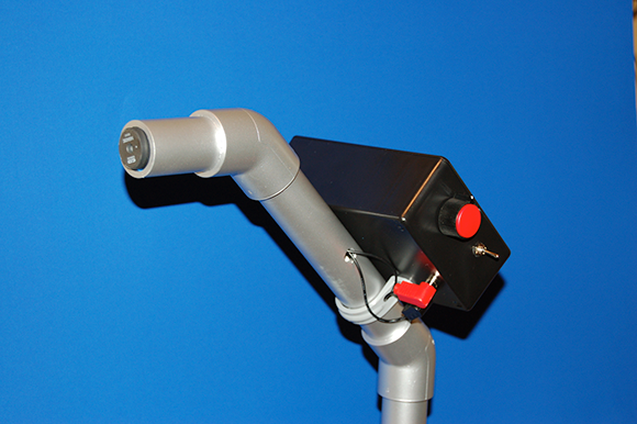
Figure 2-1: The handheld metal detector.
Here are the general tasks you need to do to build the metal detector:
1. Construct a simple electronic circuit containing a coil, a proximity detector IC, a transistor (which we describe in Book II, Chapter 6), a couple of resistors (see Book II, Chapter 2) and an LED.
2. Install the circuit in a box with batteries and an on/off switch.
3. Mount the box on a handle made from plastic pipe.
Scoping out the schematic
You need to put together only one breadboard for this project (we introduce breadboards in Book I, Chapter 6). Figure 2-2 shows the schematic for the board.

Figure 2-2: Schematic of the metal detector.
Here’s a tour of the schematic elements:
![]() L1 is a coil (or inductor) wired in parallel to capacitor C1; the combination of this dynamic duo is a parallel LC (inductor/capacitor) circuit (for more on capacitors, turn to Book II, Chapter 3). When a signal that oscillates at several kilohertz (kHz) passes through this circuit, the signal creates an electric field around the coil. When you bring the coil near to a metallic object, that electric field induces an oscillating signal in the object, which in turn creates an electric field that induces current in the coil. This current changes the oscillating signal running through the LC parallel circuit.
L1 is a coil (or inductor) wired in parallel to capacitor C1; the combination of this dynamic duo is a parallel LC (inductor/capacitor) circuit (for more on capacitors, turn to Book II, Chapter 3). When a signal that oscillates at several kilohertz (kHz) passes through this circuit, the signal creates an electric field around the coil. When you bring the coil near to a metallic object, that electric field induces an oscillating signal in the object, which in turn creates an electric field that induces current in the coil. This current changes the oscillating signal running through the LC parallel circuit.
![]() IC1 is a TDA0161 proximity detector. This IC is designed to supply the oscillating signal that’s sent through the LC parallel circuit. The IC also responds to any changes in the signal: the IC has an output of 1 milliamp (mA) or less if the coil is far from a metallic object and an output of 10 mA or higher if the coil is near to a metallic object.
IC1 is a TDA0161 proximity detector. This IC is designed to supply the oscillating signal that’s sent through the LC parallel circuit. The IC also responds to any changes in the signal: the IC has an output of 1 milliamp (mA) or less if the coil is far from a metallic object and an output of 10 mA or higher if the coil is near to a metallic object.
![]() R1 and R2 are resistors that are used to calibrate the circuit in IC1 to the LC circuit. You carry out this calibration by adjusting the value of R2 (which is a variable resistor) when the coil isn’t near to any metal objects.
R1 and R2 are resistors that are used to calibrate the circuit in IC1 to the LC circuit. You carry out this calibration by adjusting the value of R2 (which is a variable resistor) when the coil isn’t near to any metal objects.
![]() R5 is a resistor connected between the output of IC1 and ground. When the output of IC1 is on, current flows through this resistor and provides a positive voltage to the base of Q1.
R5 is a resistor connected between the output of IC1 and ground. When the output of IC1 is on, current flows through this resistor and provides a positive voltage to the base of Q1.
![]() Q1 is a 2N3904 transistor that you connect to the output of IC1. When the output of IC1 is high, Q1 turns on and allows current to flow through LED1.
Q1 is a 2N3904 transistor that you connect to the output of IC1. When the output of IC1 is high, Q1 turns on and allows current to flow through LED1.
![]() LED1 is the indicator light used to indicate that the device has detected metal in the vicinity.
LED1 is the indicator light used to indicate that the device has detected metal in the vicinity.
![]() R3 is a resistor that limits the amount of current flowing through LED1, preventing it from burning out.
R3 is a resistor that limits the amount of current flowing through LED1, preventing it from burning out.
![]() S1 is the on/off switch.
S1 is the on/off switch.
Sticking to adhesive precautions
You use PVC glue to connect the PVC pipe fittings that form the detector’s handle. You can buy various types of such adhesive at building supply and DIY shops.
 PVC adhesives are very powerful chemicals. Wear some form of work gloves to avoid getting the glue on your hands. Read the label for safety tips, such as using the glue in a well-ventilated area and what to do if some does come in contact with your skin.
Perusing the parts
Even though this project doesn’t require all that many parts, you still have to go out and buy or assemble them. Several of the parts are shown in Figure 2-3. Here’s what you need:
![]() Two 1 kΩ (kohm) resistors rated for 1/2 W, 5% tolerance (R1, R4)
Two 1 kΩ (kohm) resistors rated for 1/2 W, 5% tolerance (R1, R4)
![]() One 10 kΩ 1/2 W or 1 W knob-operated, panel mounting potentiometer (R2) such as the Vishay P16NM103KAB15 from Mouser (online, at
One 10 kΩ 1/2 W or 1 W knob-operated, panel mounting potentiometer (R2) such as the Vishay P16NM103KAB15 from Mouser (online, at uk.mouser.com) (We describe potentiometers in Book II, Chapter 2.)
![]() One 330 Ω resistor rated for 1/2 W, 5% tolerance (R3)
One 330 Ω resistor rated for 1/2 W, 5% tolerance (R3)
![]() One 120 Ω resistor rated for 1/2 W, 5% tolerance (R5)
One 120 Ω resistor rated for 1/2 W, 5% tolerance (R5)
![]() Two 0.0047 microfarad (μF) ceramic capacitors (C1, C3)
Two 0.0047 microfarad (μF) ceramic capacitors (C1, C3)
![]() One 2N3904 transistor (Q1)
One 2N3904 transistor (Q1)
![]() One T-1 3⁄4 LED (LED1)
One T-1 3⁄4 LED (LED1)
![]() One LED panel-mount socket (T-1 3⁄4)
One LED panel-mount socket (T-1 3⁄4)
![]() One TDA0161 proximity detector (IC1)
One TDA0161 proximity detector (IC1)
![]() One battery pack for 4 AA batteries
One battery pack for 4 AA batteries
![]() One 680 microhenrys (680µH) bobbin-type inductor (L1)
One 680 microhenrys (680µH) bobbin-type inductor (L1)
 We use C&D Technologies part #1468420C from Mouser (
uk.mouser.com).
![]() One single-pole, single-throw (SPST) toggle switch, used as the on/off switch
One single-pole, single-throw (SPST) toggle switch, used as the on/off switch
![]() One 400-pin breadboard
One 400-pin breadboard
![]() Four 2-pin terminal blocks (5.08mm pitch)
Four 2-pin terminal blocks (5.08mm pitch)
![]() One knob (for the potentiometer)
One knob (for the potentiometer)
![]() Two phono jacks
Two phono jacks
![]() Two right-angle phono plugs
Two right-angle phono plugs
We use right-angle plugs to avoid having a loop of wire coming out of the box. You can also use banana plugs and jacks.

Figure 2-3: Key components of the metal detector.
![]() An enclosure (we suggest a plastic box, 15 x 10 x 5 cm)
An enclosure (we suggest a plastic box, 15 x 10 x 5 cm)
![]() An assortment of different lengths of prestripped, short 0.7 mm diameter wire
An assortment of different lengths of prestripped, short 0.7 mm diameter wire
![]() Two PVC 45° joints with 2.5 cm slip fitting on both ends (one male and one female)
Two PVC 45° joints with 2.5 cm slip fitting on both ends (one male and one female)
![]() One PVC 2.5 cm end cap with 2.5 cm female slip fitting
One PVC 2.5 cm end cap with 2.5 cm female slip fitting
![]() One 2.5 cm diameter PVC pipe, 2.5 cm in length
One 2.5 cm diameter PVC pipe, 2.5 cm in length
![]() One 2.5 cm clamp to attach the enclosure to the pipe
One 2.5 cm clamp to attach the enclosure to the pipe
![]() Two 1.3 cm 8-32 (6.35 mm) panhead screws
Two 1.3 cm 8-32 (6.35 mm) panhead screws
![]() Two 8-32 (6.35 mm) nuts
Two 8-32 (6.35 mm) nuts
Taking Construction Step by Step
Although the metal detector circuit is simple, you need to carry out a few steps to build it and then put the whole thing together, including building the handle and attaching the circuit to it.
Assembling your metal detector circuit
The circuit in this project sends a detector signal and processes the signal that comes back to light up the LED. Here are the steps involved:
1. Place the TDA0161 (IC1), 2N3904 (Q1) and four terminal blocks on the breadboard, as shown in Figure 2-4.
To help, we show the transistor pinout (Q1) in Figure 2-5.

Figure 2-4: Install the IC (pin 1 goes top right), transistor and terminal blocks (TB) on the breadboard.

Figure 2-5: The 2N3904 pinout.
2. Insert wires to connect the battery terminal block and the transistor emitter pin to the ground bus.
Then insert a wire between the two ground buses to connect them, as shown in Figure 2-6. Two shorter wires connect components to the ground bus; the long wire on the right connects the two ground buses.

Figure 2-6: Connect the components to the ground bus and then connect the two ground buses.
3. Insert wires to connect IC1 and the battery terminal block to the +V bus.
Then insert a wire between the two +V buses to connect them, as shown in Figure 2-7.
4. Insert wires to connect the IC and discrete components, terminal block for the coil (L1), terminal block for the potentiometer (R2) and terminal block for the LED.
We show these connections in Figure 2-8.
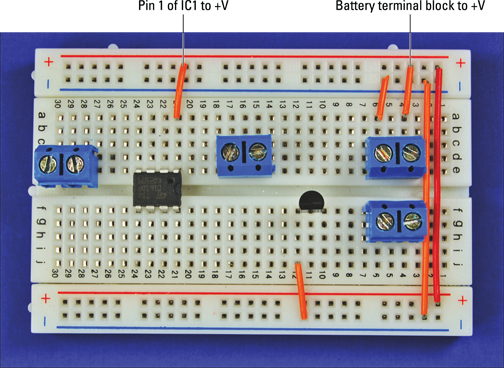
Figure 2-7: Connect the components to the +V bus.

Figure 2-8: Hook up the ICs, terminal blocks (TB) and discrete components.
5. Insert two 0.0047 μF capacitors (C1 and C2), two 1 kΩ resistors (R1 and R4), one 330 Ω resistor (R3) and one 120 Ω resistor (R5) on the breadboard, as shown in Figure 2-9.
Clipping the wire leads on components can cause small bits of metal to fly through the air. Make sure that you wear your safety goggles when clipping leads!
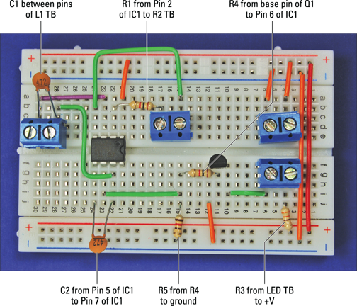
Figure 2-9: Insert resistors and capacitors on the breadboard.
Building the box to house the circuit
The box containing the circuit needs holes so that you can attach the LED, the potentiometer dial (for adjusting resistance on the IC) and the on/off switch, as well as various wire connections.
Follow these steps to get the metal detector circuit enclosure ready:
1. Drill holes in the box where you plan to mount the LED, potentiometer, audio jacks, on/off switch and clamp.
We put the on/off switch and the potentiometer on one side of the box, the LED on one end and the audio jacks on the bottom, as Figure 2-10 shows. But the placement is up to you.
We always advise that you use safety goggles when drilling.
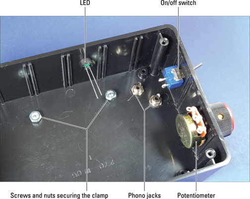
Figure 2-10: Box with on/off switch, phono jacks, potentiometer and LED in place.
2. Slip the threads of the phono jacks through the drilled holes and secure with the nuts provided with the jacks.
3. Slip the shaft of the on/off switch through the drilled hole and secure with the nut provided.
4. Slip the shaft of the potentiometer through the drilled hole and secure with the nut provided.
5. Place the knob on the potentiometer shaft and secure with the set screw.
6. Feed the top half of the LED socket through the drilled hole from outside the box and insert the LED into the top half of the socket from inside the box.
7. Position the bottom half of the socket over the leads and snap onto the top half of the socket to secure the LED.
8. Solder the black wire from the battery pack to one lug of the on/off switch and solder a 20 cm black wire to the remaining lug of the on/off switch, as shown in Figure 2-11.

Figure 2-11: Wires soldered to on/off switch, potentiometer, phone jacks and LED.
9. Solder a 20 cm wire to the centre potentiometer lug and another 20 cm wire to the left potentiometer lug, as shown in Figure 2-11.
10. Solder a red 20 cm wire to the long lead of the LED and a black 20 cm wire to the short lead of the LED, as shown in Figure 2-11.
11. Slip a 2.5 cm piece of heat-shrink tubing over each solder joint and use a hair dryer to secure them in place.
12. Solder a 20 cm wire to the lug on each of the phono jacks, as shown in Figure 2-11.
See Book I, Chapter 7 for advice about safe soldering if you’re not very experienced in this art.
Putting it all together
After you’ve built your box and circuit, you’re ready to introduce them to each other. Follow these steps:
1. Attach Velcro to the breadboard and the box and secure the breadboard in the box.
2. Attach Velcro to the battery pack and the box and secure the battery pack in the box.
3. Insert the wires from the LED, potentiometer, on/off switch and battery pack to the terminal blocks on the breadboard, as shown in Figure 2-12.
4. Secure the wires with wire clips where needed.
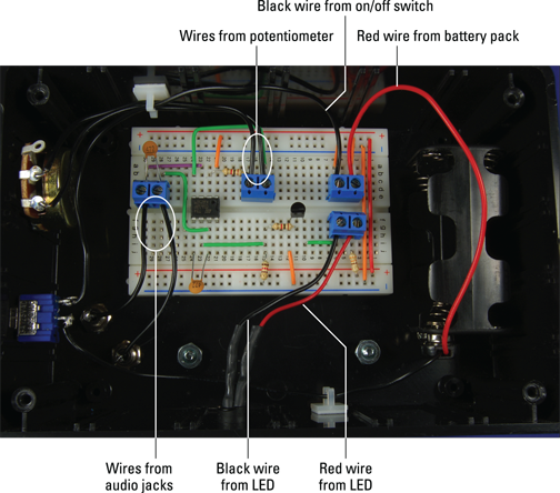
Figure 2-12: Connect the LED, potentiometer, on/off switch, coil and battery pack to the breadboard.
 As you insert the various wires in Step 3, cut each of them to a sufficient length to reach the assigned terminal block and strip the insulation from the end of the wires.
Handling the handle
To wander around easily while pointing the metal detector at suspected deposits of metal, you need a handle:
1. Glue a 20 cm length of 2.5 cm diameter PVC pipe into one end of a 45° angle PVC pipe fitting, facing up (see Figure 2-13).
2. Glue the other 45° PVC pipe fitting onto the other end of the PVC pipe, facing down (see Figure 2-13).
3. Glue a 7.5 cm length of 2.5 cm diameter PVC pipe into the open end of one of the 45° pipe fittings to form the coil end of the metal detector.
4. Glue a 15 cm length of 2.5 cm diameter PVC pipe into the open end of the other 45° fitting, which becomes the handle end of the metal detector.
5. Glue the 2.5 cm PVC cap on the open end of the 15 cm PVC pipe.

Figure 2-13: PVC pipe and fittings made into a handle for the metal detector.
6. Drill a 1 cm hole (for feeding the wires from the inductor to the box containing your circuit) in the middle of the long section of PVC pipe on the side that’s going to be on your left when you’re holding the metal detector (see Figure 2-13).
7. Solder 30 cm wires to each of the two inductor leads, and slip a 2.5 cm segment of heat-shrink tubing over each solder joint, using a hair dryer to secure the tubing in place (see Figure 2-14).

Figure 2-14: Wires attached to inductor.
8. Twist together the free ends of the wires from the inductor and feed them through the PVC pipe from the coil end until the end of the wire strand reaches the 1 cm hole.
9. Form a hook shape with a piece of 0.7–0.8 mm diameter wire and pull the wires through the 1 cm hole.
10. Insert the inductor in the end of the 2.5 cm PVC pipe, as shown in Figure 2-15, and use some glue to secure the inductor in the pipe.
11. Cut the wires to allow 7.5 cm to extend from the 1 cm hole in the pipe and attach each wire to a right-angle phono plug, as shown in Figure 2-16, using a plug that requires soldering to the wire or one that uses a screw to secure the wire, as we do.

Figure 2-15: Inductor in the end of the PVC pipe.

Figure 2-16: Phono plugs attached to wires from inductors.
12. Press the clamp onto the 2.5 cm PVC pipe and attach the box to the clamp with the 8-32 screws and nuts (Figure 2-17 shows the box attached to the handle).
13. Plug the right-angle phono plugs into the phono jacks, as shown in Figure 2-17.

Figure 2-17: Box attached to the handle and phono plugs in place.
If you’re left-handed, consider placing the hole in Step 3 on the side that’s going to be on your right when you’re holding the detector. Doing so allows you to hold the handle in your left hand and operate the switches with your right hand.
We show the finished metal detector in Figure 2-18.

Figure 2-18: The finished metal detector.
Trying Out Your Detector
You probably have a fortune in ancient coins waiting to be discovered in your garden, and so when you’ve built your detector don’t waste any time – get outside and see what you can find! Here’s how to make your gadget work:
1. Insert the batteries.
Secure the lid on the box with the screws provided and flip the on/off switch to ‘On’.
2. Hold the coil away from any metal, turn the potentiometer knob so that the LED is on and then turn the knob slightly in the other direction until the LED turns off.
Doing so calibrates the IC so that small changes in the oscillating signal that runs through the coil trigger it.
3. Experiment with your detector by holding it near to different items containing metal.
You can usually detect coins and keys in trouser pockets as well as various types of tools and nails at a distance of about 1.3 cm. You should be able to detect larger metal objects (such as that space shuttle in your garden shed) at a distance of about 2.5 cm. That’s not very powerful we admit, but it’s a metal detector and you made it!
If you don’t get the right results, here are some remedies to try:
![]() Check that all the batteries are fresh, tightly inserted in the battery pack and all facing the right direction.
Check that all the batteries are fresh, tightly inserted in the battery pack and all facing the right direction.
![]() Check that no wires or components have come loose.
Check that no wires or components have come loose.
![]() Compare your breadboard against the photos to make sure that all the wires and components are connected correctly.
Compare your breadboard against the photos to make sure that all the wires and components are connected correctly.
Metal detectors are incredibly addictive (well, maybe not, but they’re fun to mess around with). Here are some other things to try with your detector:
![]() Adapt your detector so that it activates a buzzer, by simply replacing the LED in the circuit with a buzzer.
Adapt your detector so that it activates a buzzer, by simply replacing the LED in the circuit with a buzzer.
![]() Make a more powerful detector that can find coins several centimetres under the sand on the beach. Check online for other metal detector circuits with more oomph (for example,
Make a more powerful detector that can find coins several centimetres under the sand on the beach. Check online for other metal detector circuits with more oomph (for example, www.thunting.com specialises in metal detectors you can use for hunting treasure).