
Chapter 4
Interfacing to Your Computer’s Parallel Port
In This Chapter
![]() Getting to know the parallel port
Getting to know the parallel port
![]() Programming the parallel port
Programming the parallel port
![]() Displaying numbers
Displaying numbers
![]() Increasing the current
Increasing the current
Electronics by itself can do some pretty amazing things, but when you combine it with the power of your computer you can start to dream big: complicated toys such as remote-controlled automatons, useful equipment such as watering routines for the garden and special lighting schemes for your living room.
Just imagine: you can entertain the children by giving them a fright on Halloween; or rig up some simple home automation to let potential burglars believe that someone’s at home when you’re out; or create something more often found in a Bond villain’s lair. Almost anything is possible – the only limit is your imagination (though devising over-complicated ways of disposing of spies is way beyond the scope of this book!)
Building such systems may take you some time, depending on how complex you want them to be, but it needn’t cost you loads of money. To start with all you need is an old computer – the sort you can find thrown away in a skip – and a circuit board that activates mechanical relays in response to output from the computer. You then run a simple software program on the computer to send signals to the relays via the computer’s parallel-printer port, to make electronic events happen. Alternatively, you could add parallel ports to a more up-to-date computer using an expansion card or USB adaptor (available online and from stores like Maplin – just search for ‘parallel card’ or ‘USB parallel’). To install a card you’d have to follow the manufacturer’s instructions in opening up the back of your computer and inserting the card into the right slot. The adaptor just plugs into a USB port but may require you to install driver software for it to work. Overall, it’s a much better idea - and much less work! - to get hold of an old computer from somewhere.
In this chapter, you discover how to create your own circuits that you can control via a parallel-printer port, so that you can build your own impressive contraptions. We introduce you to the parallel port and how to program it, and suggest kit for increasing the current for more powerful applications to amaze your friends and family. They may even come to think of you as a genius – even if it’s an evil one bent on world domination (white cat on your lap is optional)!
Understanding the Parallel Port
Until a few years ago, all computers came equipped with a parallel port, which was used mostly to connect to a printer. Today, most printers connect to computers via USB (Universal Serial Bus) ports. USB has many advantages over parallel port, the most significant being faster data transfer and smaller cables.
The lowly parallel port has one advantage over USB ports, however: it makes creating your own circuits that interface directly with the port easy. These circuits can control low-current devices such as light-emitting diodes (LEDs), or activate transistors or mechanical relays that in turn activate high-current devices such as motors, incandescent lamps or sound systems.
After you build the circuits to connect to a parallel port, creating a software program on the computer that sends data to the parallel port is a doddle. When you run this program, your circuit detects the data sent to the parallel port to control LEDs or other low-power circuits.
Peering into the makeup of a parallel port
A standard parallel port has eight data pins, which are essentially transistor-transistor logic (TTL) outputs, with +5 V high representing 1 and 0 V low representing 0. In fact, the first parallel-printer ports designed for the IBM PC back in 1980 used 7400-series logic chips. Check out Chapter 3 of this minibook for all about TTL and logic chips.
The TTL logic levels used by the parallel port allow you to create logic circuits that interface with the output from a parallel port. You build a circuit that connects to a parallel port, use software on the computer to send data to the parallel port and your circuit can respond to the data you send.
 Unfortunately, few computers today come with a built-in parallel port. Before you waste your time building circuits to interface with a parallel port, you need to find a computer that has one. Your best bet is to scavenge for an old machine. Look for one from before the year 2000, because most computers of that age have a parallel port, and one running Windows 95 or Windows 98 operating systems (O/S). If you can’t find such an old Windows O/S, consider installing one of the free distributions of the Linux O/S available (just fire up a search engine and search for ‘Linux’ to get started).
A computer that old costs you next to nothing. Ask friends and family first and then look in car boot sales or local junk or computer repair shops. The computer isn’t going to be much good for anything else, but dedicating a computer solely to your electronics work is a good idea.
 If you wire the circuit that interfaces with the parallel port incorrectly, you risk damaging the computer’s internal circuitry. Far better to fry an old computer than your latest laptop with all your precious files on it!
 If you prefer, you can choose controllable circuit boards that use the more modern USB interface instead of the old parallel port. This chapter explains parallel-port programming to give you a basic understanding of how to control circuit boards from a PC, but USB boards like the Arduino are very capable and more widely available. Go to
 www.arduino.cc to find out more about Arduino and where to buy the boards. Or look out for the Wiley book on the subject, Arduino Projects For Dummies by Brock Craft.
Connecting with the DB25 connector and its pins
A parallel-printer port uses a standard type of connector called a DB25 connector, which has 25 pins. Each of these pins serves a different purpose in the port’s communication with a printer.
Like most data connectors, DB25 connectors come in male and female variants. The male DB25 connectors consist of 25 pins and the female connectors have 25 holes. Figure 4-1 shows how the pins and holes of a DB25 female and male connector are numbered. As you can see, the connector consists of two rows of pins. The top row has 13 pins and the bottom row has 12. The pin in the top-right corner of the female connector is designated as pin 1; the pin at top left is pin 13; pin 14 is at bottom right; and pin 25 is at bottom left.
The pin numbers for a male connector are the mirror image of the numbers of the pins in the female connector. This arrangement of pins – or pinout – is necessary so that when the male connector is plugged into the female connector the pins connect properly (for example, pin 1 connects to pin 1, pin 2 connects to pin 2 and so on).

Figure 4-1: Pinouts for a DB25 connector.
Pinning your hopes on the pinout assignments
Table 4-1 lists the pinout assignments for a standard parallel port.

For the purposes of this chapter, the pins you’re most interested in are numbered 2–9, which are collectively called the data port. When you connect the data port to a printer, its eight pins are capable of sending 1 byte of data at a time to the printer. When you connect it to a circuit of your own design, its pins operate as eight separate logic outputs, which you can use as inputs to your own logic circuits.
A parallel port also features four additional output pins (numbered 1, 14, 16 and 17) called the control port, which you can also use for output. When you connect the control port to a printer, these pins are used to control the operation of the printer. One of them, called the strobe, indicates that a new byte of data is available on the data pins; when the strobe pin goes high, the printer reads a byte of data from the data pins. Another control-port pin resets the printer.
The five pins numbered 10–13 and 15 that make up the status port allow the printer to send information back to the computer. One of the status-port pins lets the printer tell the computer that it’s ready to receive data via the data port. Another pin lets the printer know that it has finished reading data from the data port. A third pin informs the computer that the printer is out of paper. The other status pins have similar functions.
When you connect the status port to a circuit of your own design, its pins can be used to send information to the computer. You can use the status pins to tell the computer that a switch has been closed, that a light sensor detects light or that a water-level sensor has reached a certain level.
Unfortunately, the programming required to detect the presence of input on one of the status-port pins is a bit too complex for this chapter. If you’re an experienced C or C++ programmer, you’ll have no trouble writing programs to read the status-port pins. But C and C++ programming are beyond the scope of this book, and so we focus on sending output to the parallel-port data pins.
 The output pins of a parallel port use a +5 V high signal to represent 1 and 0 V to represent 0. The amount of current that each pin can source is relatively small – typiacally around 10–12 milliamperes (mA). That’s enough current to drive an LED, but for anything more demanding you need a way to isolate the output load from the parallel port itself. To do that, you can use individual transistors or an integrated circuit (IC) designed specifically for this purpose. For details, read ‘Using Darlington Arrays to Drive High-Current Outputs’, later in this chapter.
Designing a parallel-port circuit
Figure 4-2 shows the two methods for connecting output devices to a parallel-port data pin. The top circuit drives an LED directly. A current-limiting resistor is required to prevent the LED from pulling too much current and damaging the LED, the parallel port itself or both.
The bottom circuit in Figure 4-2 shows how to use a transistor to switch a circuit by using the output from a parallel-port data pin. As you can see, the data pin is connected through a resistor to the transistor’s base. When the data pin goes high, the transistor is turned on, allowing current to flow through the collector-emitter circuit.
Using a transistor driver this way provides two benefits:
![]() The transistor can switch more than the 10–12 mA that the parallel port’s data pin can source directly.
The transistor can switch more than the 10–12 mA that the parallel port’s data pin can source directly.
![]() The collector-emitter circuit can operate at a different voltage from the one that the data pin’s +5 V high signal provides.
The collector-emitter circuit can operate at a different voltage from the one that the data pin’s +5 V high signal provides.
When you build Project 4-1 later in this chapter, you see an example of a circuit that uses the first method to connect to parallel-port output. This project connects eight LEDs to the eight data pins. With the cable to connect this circuit to a computer’s parallel port and the right software in place on the computer, you can write simple scripts that flash the LEDs on and off in just about any sequence you desire.

Figure 4-2: Two ways to connect an LED to a parallel-port output pin.
Working with DB25 connectors
To build your own circuits that interface with a parallel port, you need to use a DB25 connector that attaches to your circuit. The standard parallel port on a computer uses a DB25 female connector, which means that you need to provide a DB25 male connector for your circuits.
You have several ways to fashion a DB25 connector for your circuits. The simplest method is to find an old parallel printer cable, cut it six or seven centimetres past the male end, strip back the insulation and separate the 25 wires that run inside the cable. Strip the ends of each of these wires and then use your ohmmeter (see Book I, Chapter 8) to match up wire with the individual pins on the connector.
Keep good notes so that you know which wires to use for your circuits.
Alternatively, you can purchase a male DB25 connector and solder wires to each of the pins. Figure 4-3 shows a connector that we made to use along with Projects 4-1 and 4-2, which appear later in this chapter. We solder eight red wires to pins 2–9 (the data pins) and one black wire to pin 25 (one of the ground pins).

Figure 4-3: A male DB25 connector with leads soldered to the data pins and one of the ground pins.
If you plan to complete Project 4-1 or Project 4-2, you need to assemble a similar cable yourself. All you need are a male DB25 connector, some 18-AWG or 22-AWG solid wire, some solder, a soldering iron and a vice to hold the connector while you solder (check out Book I, Chapter 7, for all about soldering). You may also want to get some magnifying goggles; although they make you look like the mad professor in Back to the Future, they do make the job much easier by helping you see the project more closely.
Controlling Parallel-Port Output from an MS-DOS Prompt: Programming from a PC
Project 4-1 (see ‘Building a Parallel-Port LED Flasher’, later in this chapter) covers the details of building a simple breadboard project that lets you control eight LEDs from a computer’s parallel port.
You can plug the project directly into the parallel port on the back of your computer, or you can use a short male-to-female DB25 printer cable to connect the project to the computer (see the earlier section ‘Connecting with the DB25 connector and its pins’). Either way, you need some special software on the computer to send data to the parallel port to turn on the LEDs. Fortunately, you don’t have to be a programmer to create this software, because software that does this job is readily available on the Internet.
The simplest software is designed to work with a popular kit that lets you connect relays to the parallel port. We describe this kit, called Kit 74, in 'Using a Kit 74 Relay Controller', later in this chapter. To find the software online, just search for 'Kit 74 software'. The software is contained in an archive file named k74_dos.zip. Download it to your computer and extract its contents to a folder on your hard drive named C:k74_dos.
To use the commands in an O/S prior to Windows 7, click the Windows Start button, click Run, type cmd and press the Enter key. An MS-DOS command window opens (see Figure 4-4).

Figure 4-4: You can run an MS-DOS command to send data to the parallel port.
Type the following command, and press Enter:
cd k74_dos
This command transfers you to the folder in which you saved the Kit 74 commands. Then you can type and run the commands to test your parallel-port circuits.
The Kit 74 DOS software consists of three commands – RELAY, DELAY and WAITFOR – that you can run from a command prompt. We explain these three commands in the following sections.
Using the RELAY command
The RELAY command sends a single byte of data to the parallel port. Each of the eight output pins is set high or low, depending on the byte you send. This command sets all eight pins to high:
RELAY FF
The following command sets all eight outputs to low:
RELAY 00
Unfortunately, most versions of the RELAY command available on the Internet have a bug that requires you to issue the command twice to get it to work. So you have to enter the command RELAY FF twice in sequence to turn on all the output pins.
You need to specify the output data as a single hexadecimal (or hex) number (which is a special number made of the numerals 0–9 and the letters A–F). Table 4-2 shows the hexadecimal numbers to use for each of the eight output pins.
Table 4-2 Hex Values for Data Output Pins
|
Data Pin |
Hex Value |
|
1 |
01 |
|
2 |
02 |
|
3 |
04 |
|
4 |
08 |
|
5 |
10 |
|
6 |
20 |
|
7 |
40 |
|
8 |
80 |
To turn all the pins on, use the value FF. To turn them all off, use the value 00.
To turn more than one pin on or off, you need first to calculate the eight-bit binary number equivalent of the pins you want to set. To turn on pins 1, 2, 3 and 8, for example, you use the binary value 10000111. (Notice that pin 1 is represented by the rightmost bit of the binary number and that pin 8 is the leftmost bit.) To bone up on binary, flip to Chapter 1 of this minibook.
After you work out the binary number for the pins you want to set, split it in half so that you have two four-bit numbers. In the example that sets pins 1, 2, 3 and 8, the first binary number is 1000 and the second is 0111.
Finally, look up each four-bit number in Table 4-3 to determine the single hexadecimal digit to use. For this example, the first four-bit number converts to 8 and the second four-bit number converts to 7. Combining these two numbers gives you the hexadecimal number 87. Thus, the command to turn on pins 1, 2, 3 and 8 is:
RELAY 87
You have to enter this command twice to get it to work.

Creating a command script
You can easily create command scripts that can execute a series of RELAY commands in sequence. Just use Notepad (the simple text editor that comes free with all versions of Windows) to enter a series of RELAY commands, one on each line. Save the file to the C:k74_dos folder, using the file extension .bat. Then you can run your script by typing the name of your script file (without the .bat extension) in the MS-DOS command window.
Figure 4-5 shows a simple script created with Notepad. Notice that this script contains two identical RELAY commands because of the bug in the RELAY command that requires you to run the command twice to get it to work.

Figure 4-5: A simple script in a Notepad window.
On an older Windows computer (the kind that’s likely to have a parallel port to play with), you find Notepad in the Start menu under Accessories.
Besides the RELAY command (and the DELAY and WAITFOR commands, which we explain in the following section), you often use two special MS-DOS commands in command scripts. The first command is called a label, which lets you give a name to a line in your script. Labels are indicated by a colon followed by a short word. :LOOP is a typical label.
The second command, called GOTO, creates a program loop by telling the script to jump to a label. Labels and GOTO commands are always used together, as follows:
:LOOP
RELAY FF
RELAY FF
GOTO LOOP
This sequence of commands causes the two RELAY commands to be executed. Then the GOTO command sends the script back to the :LOOP label command, which executes the RELAY commands again. The commands between the GOTO command and the label are executed again and again until you stop the script by pressing Ctrl+C or closing the command window.
Listing 4-1 shows a simple script that quickly flashes the LEDs in sequence, beginning with LED1. When the script gets to LED8, it reverses the direction and flashes the LEDs back to LED1. Then a GOTO command sends the script back to the :LOOP label to repeat the flashing. The resulting effect is that the LEDs sweep back and forth indefinitely.
This script is named CYLON.BAT because it resembles the flashing eyes of the evil Cylons from the classic science-fiction TV series Battlestar Galactica.
Listing 4-1: The CYLON.BAT Script
:LOOP
RELAY 01
RELAY 01
RELAY 02
RELAY 02
RELAY 04
RELAY 04
RELAY 08
RELAY 08
RELAY 10
RELAY 10
RELAY 20
RELAY 20
RELAY 40
RELAY 40
RELAY 80
RELAY 80
RELAY 40
RELAY 40
RELAY 20
RELAY 20
RELAY 10
RELAY 10
RELAY 08
RELAY 08
RELAY 04
RELAY 04
RELAY 02
RELAY 02
RELAY 01
RELAY 01
GOTO LOOP
Seeing why timing is everything: DELAY and WAITFOR
The Kit 74 software includes two timing commands that let you add delays to your scripts. By incorporating delays, you can control the timing of the devices controlled by your parallel-port circuit. For example, you can turn pin 1 on, wait 5 minutes and then turn it off again.
The most useful of the timing commands is DELAY, which simply causes your script to pause for a certain number of seconds. To delay your script for 10 seconds, for example, use this command:
DELAY 10
The following sequence shows how to turn all outputs on and off at 1-second intervals:
:LOOP
RELAY FF
RELAY FF
DELAY 1
RELAY 00
RELAY 00
DELAY 1
GOTO LOOP
This sequence starts by turning on all the output pins. Then it waits 1 second, turns all the outputs off, waits another second and jumps to the LOOP label to start the sequence all over again.
You always need to specify the delay period in seconds. To wait 1 minute, use this command:
DELAY 60
An hour contains 3,600 seconds, and so the following command delays the script for 1 hour:
DELAY 3600
The second timing command is WAITFOR, which waits to execute until a certain time of day arrives. To stop your script until 10:30 a.m., for example, use this command:
WAITFOR 10:30
Here’s a sequence that turns all outputs on at 10:30 a.m. every day, leaves them on for an hour and turns them off:
:LOOP
WAITFOR 10:30
RELAY FF
RELAY FF
DELAY 3600
RELAY 00
RELAY 00
GOTO LOOP
Building a parallel-port LED flasher
Project 4-1 presents a simple breadboard circuit that connects eight LEDs to the eight output pins of a parallel port. To complete this project, you need to have a computer with a parallel port and install the Kit 74 parallel-port software (refer to ‘Controlling Parallel-Port Output from an MS-DOS Prompt: Programming the Port’, earlier in this chapter).
You also need to build a parallel-port connector that you can attach to your circuit. Refer to the earlier Figure 4-3 for information on building the required connector.
After you assemble the circuit, you can test it by connecting it to your computer's parallel port, opening a command prompt and using the RELAY command to send data to the port. To turn on all eight LEDs, for example, run this command:
RELAY FF
The flaw in the RELAY command means that you need to run the command twice.
After the circuit works properly when you enter the RELAY command from the command prompt, try running the CYLON.BAT script from Listing 4-1 earlier in this chapter. This script flashes the LEDs sequentially from left to right and back again. The LEDs run repeatedly until you terminate the batch file by pressing Ctrl+C or closing the command window.
Figure 4-6 shows the finished parallel-port LED flasher circuit. You can see in the photo that we connect the male DB25 connector to one end of a parallel printer cable. The other end of this cable is connected to the computer.

Figure 4-6: The finished parallel-port LED flasher circuit (Project 4-1).


Sussing out Seven-Segment Displays
A seven-segment display is an array of seven LEDs arranged in a way that can display numerals as well as some alphabetic characters. You see this type of display most often on calculators, which have several seven-segment displays arranged side by side to display numbers. You can purchase an inexpensive (less than £2) seven-segment display at your local electronics-parts shop.
Introducing the seven-segment display
You may be wondering why we’re talking about seven-segment displays in a chapter on parallel-port interfacing. The reason is that to use a seven-segment display for any practical purpose you have to connect the display to a digital circuit that’s capable of controlling the individual segments to display meaningful information such as numerals or alphabetic letters. You can do that with logic gates (which we describe in this minibook’s Chapter 3), but the resulting circuits are very complicated. A much easier option is to use the power of a computer to control the individual segments via a parallel-port connection.
Figure 4-7 shows how a single-digit seven-segment display module is usually wired up. As you can see, the segments themselves are referred to by the letters a to g. This particular display module is contained in a 14-pin DIP (a dual inline package), but only 8 of the pins are used. The anode of each LED segment is connected to one of the pins. The cathodes for all the segments are connected at pin 4. (This arrangement is called common-cathode wiring. You can also get seven-segment displays in which the anodes are connected to a common pin, called common-anode wiring.)

Figure 4-7: Pinouts for a typical seven-segment display.
To control a seven-segment display, you must first connect a positive voltage source to the anode of each of the seven segments. The cathode has to be connected to ground.
Be sure to use a current-limiting resistor in series with each anode to limit the current that flows through the LEDs.
To drive a seven-segment display from your computer’s parallel port, connect the anode of each segment through a current-limiting resistor (1 kΩ is typical) to one of the data output pins. The most straightforward way to do that is to connect DATA1 (pin 2) to the a segment, DATA2 (pin 3) to the b segment and so on until DATA7 is connected to the g segment.
After you’ve connected a seven-segment display to the parallel port, you can form numerals or some alphabetic characters by sending the right data to the parallel port. Table 4-4 shows the data byte you need to send to display numerals 0–9.

Thus, to display the numeral 5, use this RELAY command:
RELAY 6D
To understand why the data values in Table 4-4 are required to display numerals on a seven-segment display, remember that each of the segments in the display is connected to one of the data output pins of the parallel port. Thus, to light a particular combination of segments to form a numeral, you need to set the parallel port’s output so that the data pins corresponding to the segments you want lit are high and the remaining pins are low.
To form the numeral 3, for example, segments a, b, c, d and g need to be turned on. Those segments are connected to data output pins 1, 2, 3, 4 and 7. Thus, you need to send a byte of data to the parallel port with the bit positions corresponding to pins 1, 2, 3, 4 and 7 set to the binary value 1 and the other bit positions set to binary 0.
In a binary number, the bit positions are numbered right to left, and so the binary pattern you need to send to the parallel port to form the numeral 3 is:
01001111
The hexadecimal equivalent for this binary number is 4F. Thus, the following command displays the numeral 3:
RELAY 4F
Listing 4-2 shows a script called COUNTDOWN.BAT that displays a NASA-style countdown from 9 to 0 at 1-second intervals. When the script reaches 0 that numeral flashes repeatedly until you cancel the batch file by pressing Ctrl+C or closing the command window. (See the 'Using the RELAY command' section earlier in the chapter to find out why each command is repeated.)
Listing 4-2: The COUNTDOWN.BAT Script
RELAY 6F
RELAY 6F
DELAY 1
RELAY 7F
RELAY 7F
DELAY 1
RELAY 07
RELAY 07
DELAY 1
RELAY 7D
RELAY 7D
DELAY 1
RELAY 6D
RELAY 6D
DELAY 1
RELAY 66
RELAY 66
DELAY 1
RELAY 4F
RELAY 4F
DELAY 1
RELAY 5B
RELAY 5B
DELAY 1
RELAY 06
RELAY 06
DELAY 1
:LOOP
RELAY 3F
RELAY 3F
RELAY 00
RELAY 00
GOTO LOOP
In this script, the :LOOP label appears near the end of the listing, not at the beginning. You can place labels anywhere you want in a script. The GOTO LOOP command at the end of the script causes the script to repeat the last four commands over and over until you interrupt the script by pressing Ctrl+C or closing the command window.
Building a seven-segment display countdown timer
Project 4-2 presents a breadboard circuit that connects a seven-segment display to seven of the eight output pins of a parallel port. As with the earlier Project 4-1, you need a computer with a parallel port and the Kit 74 software installed. You also need a parallel-port connector with wires soldered to the data pins and one of the common data ground pins. You can find information about the required software and the required cable earlier in the section ‘Controlling Parallel-Port Output from an MS-DOS Prompt: Programming the Port’.
To test your assembled circuit, connect it to your computer's parallel port, open a command prompt and use the following RELAY command:
RELAY FF
All seven of the display’s segments should light up.
If one doesn't light, carefully double-check your wiring. Also verify that your seven-segment display uses the same pinouts as the one listed in the project; some display modules have different packaging with different pin connections. Also, remember that you have to run the RELAY command twice to get it to work.
When the circuit checks out, run the COUNTDOWN.BAT script (in Listing 4-2, earlier in this chapter). The seven-segment display counts down the digits 9 to 0 at 1-second intervals. When it gets to zero, the display flashes until you terminate the batch file by pressing Ctrl+C or closing the command window.
Figure 4-8 shows the finished seven-segment-display circuit.
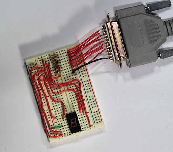
Figure 4-8: The finished parallel-port seven-segment display (Project 4-2).


Driving up the Current
Two transistors can be connected one into the other so that the current amplified by the first transistor is amplified further by the second one. This arrangement, known as a Darlington transistor (sometimes called a Darlington pair), can switch much more current than the collector-emitter circuit of a standard transistor. You can use Darlington transistors to switch up to 500 mA from the output of a parallel-port data pin, which is enough current to drive a mechanical relay or a small electric motor.
But as the next section explains, you don’t have to use individual Darlington transistors.
Using Darlington arrays forhigh-current outputs
You can use a specially designed IC for driving high-current loads from TTL-level inputs. The most common ICs of this type are the ULN2003, which has seven Darlington drivers in a 16-pin DIP package, and the ULN2803, which has eight drivers in an 18-pin DIP package. You can find these useful ICs on the Internet by searching for ‘ULN2003’ or ‘ULN2803’.
Table 4-5 lists the pinouts for the ULN2003. As you can see, pins 1–7 are the input pins, which you can connect directly to the output pins from the parallel port. Pins 10–16 are the output pins, which you can connect to the circuit you want to control. Pin 8 connects to ground and pin 9 connects to a voltage source.
Table 4-5 also shows the pinouts for the ULN2803, which are similar to the ULN2003 pinouts.

The output circuit for a ULN2003/2803 is a little different from what you may expect. Instead of sourcing current for the load, the Darlington array sinks the current. Thus, the output pin is on the ground side of the load circuit, as shown in Figure 4-9. The voltage source (Vss) feeds the load circuit (in this case, a small motor) and the ULN2003.

Figure 4-9: Driving a high-current load from the parallel port using a Darlington array.
If you want to use a ULN2003 or ULN2803 to drive an inductive load such as a relay or motor, use a Zener diode on the Vss pin, by connecting the cathode to the Vss pin and the anode to the GND pin. This diode prevents current from flowing in the wrong direction into the ULN2803 in case the relay or motor coil creates a large backward voltage spike, as coils are apt to do. Use a Zener diode with a voltage value just above the supply voltage and rated for 500 mW or above.
Building a motor driver
Project 4-3 presents a breadboard circuit that drives a small 3 V DC motor from a parallel port. This motor uses much more current than a parallel port can handle, and so you use a ULN2003 Darlington array IC to drive the motor.
As with the Projects 4-1 and 4-2 earlier in this chapter, you need a computer with a parallel port and the Kit 74 software installed, plus a parallel-port connector with wires soldered to the data pins and one of the common data ground pins. Please refer to those earlier projects for more information.
When the circuit is assembled and connected to your computer, you can test it by running the following command twice in a command window:
RELAY 01
The motor starts running. (If it doesn’t start, check all your connections and check your commands.) To stop the motor, use this command twice:
RELAY 00
You can easily write a script to run the motor for a certain interval. Listing 4-3 shows a simple example. Here, the MOTOR.BAT file simply runs the motor for 30 seconds, turns it off for 30 seconds and then jumps to the :LOOP label to repeat the cycle.
Listing 4-3: The MOTOR.BAT Script
:LOOP
RELAY 01
RELAY 01
DELAY 30
RELAY 00
RELAY 00
DELAY 30
GOTO LOOP
Figure 4-10 shows the finished motor drive circuit.

Figure 4-10: The finished parallel-port motor driver (Project 4-3).

