
Here are the commands
to edit solids and surfaces, namely, changing parameters with the PROPERTIES and QUICKPROPERTIES palettes and the SOLIDEDIT command with several useful options.
After a solid or surface creation, it's very easy to change its parameters with the PROPERTIES or QUICKPROPERTIES palettes.
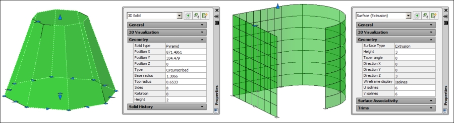
The PROPERTIES command (alias Ctrl + 1), one of the most used in AutoCAD, is also excellent for modifying the parameters that define solids or surfaces. The command displays a floating palette that can be always visible and that displays the parameters and properties of the selected object.
Selecting a solid, there are three panels related to 3D, namely, 3D Visualization, Geometry, and Solid History. The first one includes the material and shadow display only important for renderings and the last one includes history parameters for composite objects. As in 2D, under Geometry, we can verify and modify all relevant parameters of the solid or surface selected. By selecting a surface, besides Visualization and Geometry, two additional panels are available, namely, Surface Associativity and Trims, where we control associativity between surfaces and original lines and trims applied to surfaces.
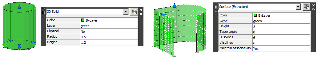
The QUICKPROPERTIES command (alias QP) also displays
a properties palette, but one that is condensed to the most important parameters and near the object. For most objects, this is the command displayed when double-clicking over that object.
Another way to apply the Quick Properties palette is to turn on the QP | Quick Properties button on the Status bar (or press Ctrl + Shift + P). With this mode activated, it is enough to select an object, without command, and the palette is immediately displayed.
When dealing with solids, it is frequently needed to modify faces, edges, and volumes.
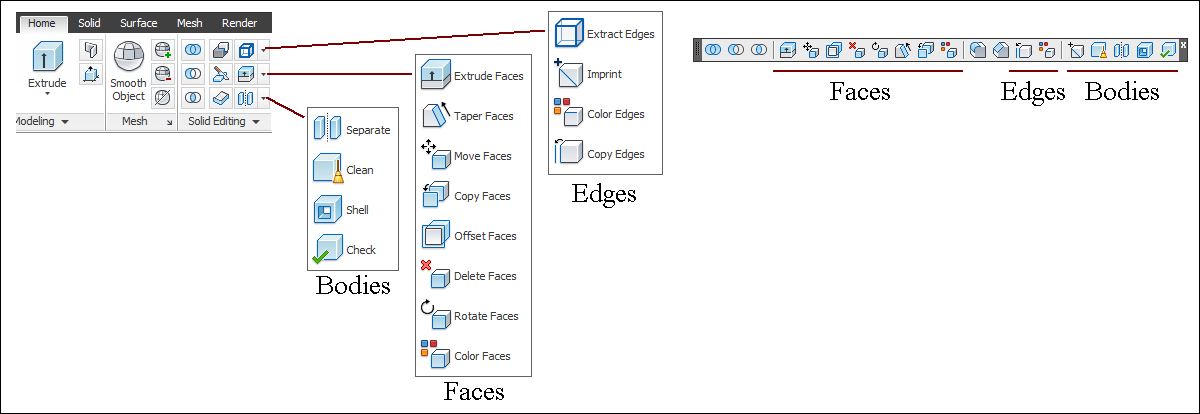
The SOLIDEDIT command (no alias) allows us to modify faces, edges, and volumes (here called bodies) of solids. To apply this command, it is faster to use the Solid Editing toolbar or the ribbon, Home | Solid Editing; we jump directly to the wanted option.
The interaction with the command starts by displaying whether the verification of solids accuracy is turned on (the SOLIDCHECK variable):
Command: SOLIDEDIT
Solids editing automatic checking: SOLIDCHECK=1
Next, the main command options are displayed. Undo undoes the last command operation and eXit ends the command. The remaining options are presented next:
Enter a solids editing option [Face/Edge/Body/Undo/eXit] <eXit>: Option
Upon entering the Face option, we have several additional options. Undo undoes the last applied option and eXit returns to the previous level. When selecting faces, Undo and Remove options are available, allowing us to undo the last selection operation or entering the mode to remove faces from the selection:
Enter a face editing option
[Extrude/Move/Rotate/Offset/Taper/Delete/Copy/coLor/mAterial/Undo/eXit] <eXit>: Option
The options are as follows:
- Extrude: This option allows you to extrude faces. It prompts for faces selection, the height of extrusion, and the angle of taper for extrusion. A positive value for height adds volume, while a negative value removes volume. An angle not equal to zero allows us to taper the new volume.
- Move: This option allows moving of faces. After selection, it prompts for displacement, for instance, with two points similar to the
MOVEcommand.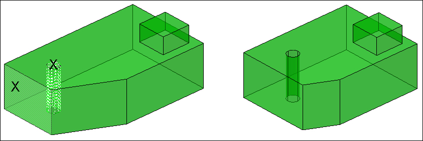
- Rotate: This option allows the rotation of faces. After selection, it prompts for the axis of rotation and the angle of rotation. The axis of rotation, by default, is specified by two points, with additional options allowing us to use an existing object or define an axis parallel to the X, Y, or Z axis of the current UCS.
- Offset: This option allows the offsetting of faces or the creation of parallel faces. After selection, it prompts for the offset distance. A positive value adds volume, while a negative value removes volume. If selecting continuous faces (for instance, on the common edge), faces are extended so that the corner is corrected.
- Taper: This option allows us to taper faces. After selection, it prompts for two points that define the taper axis and the taper angle. With positive values, end section is reduced, while with negative values, end section is increased:

- Delete: This option allows the deletion of faces. If AutoCAD knows how to fill the space, faces will be deleted.

- Copy: This option allows the copying of faces. Regions are created for all planar faces, else surfaces are created for all curved faces. After selection, it prompts for two points that define the displacement.
- coLor: This option allows changing the color of selected faces. After selection, it shows the Select Color dialog box to choose the color to apply.
- mAterial: This option allows the application of a material to selected faces, so in render, we can have different materials applied to a single object. After selection, it prompts for the name of the material to apply. This option has no icon.
When choosing the Edge option, besides the Undo and eXit options, we have two more options. When selecting edges, Undo and Remove options are available, allowing us to undo the last selection operation or entering the mode to remove edges from the selection:
Enter an edge editing option [Copy/coLor/Undo/eXit] <eXit>: Option
- Copy: This option allows the copying of edges. Depending on selected edges, arcs, circles, ellipses, lines, or splines are created. After selection, it prompts for two points that define the displacement.
- coLor: This option allows us to change the color of selected edges. After selection, it shows the Select Color dialog box to choose the color to apply.
The body represents the volume of a solid. Besides the Undo and eXit options, we have five more options:
Enter a body editing option
[Imprint/seParate solids/Shell/cLean/Check/Undo/eXit] <eXit>: Option
- Imprint: This option allows you to create edges from intersections of the selected solid with linear entities, regions, or solids. After one solid selection, it prompts for an object to imprint and then this object is erased. These two prompts are repeated until the Enter or Esc key is pressed.
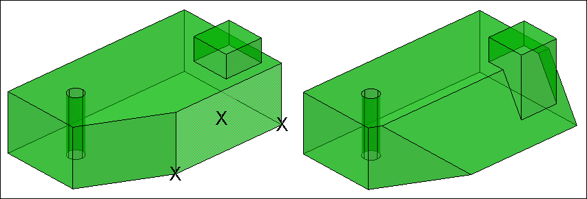
- seParate solids: If one solid has separated volumes, this option allows you to separate these volumes into independent solids. It prompts only for a solid selection.
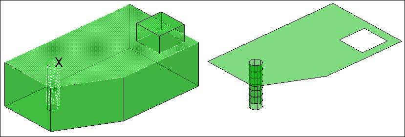
- Shell: This option allows you to create a hollow solid with a constant wall thickness, eventually open through one or more faces. We can only apply this option once to a solid. After the solid selection, it prompts for the selection of faces to remove, thus creating an open thin-wall solid, and the shell thickness. A positive thickness creates the shell on the inside, while a negative thickness creates the shell on the outside.
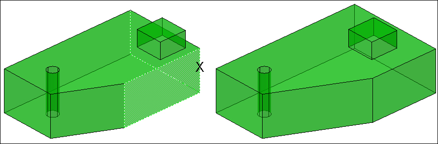
- Clean: This option allows us to remove redundant edges or vertices, but does not remove edges coming from the Imprint option.
- Check: This option verifies whether the solid is valid. It prompts only for a solid selection.
We are creating a building from exterior lines, mainly by applying the SOLIDEDIT command. It is advisable to use the Solid Editing toolbar or panel (ribbon) to access all SOLIDEDIT commands.
- Open the drawing
A3D_07_05.DWG. This drawing already has the 2D building contour. - Create and activate the layer
3D-BUILDING, color at choice. - Using
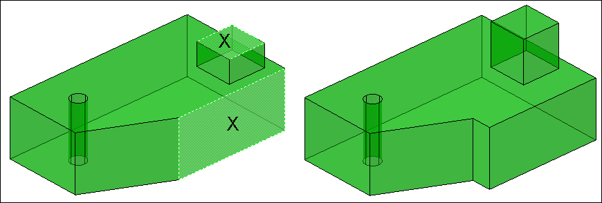
PRESSPULL, click inside the area and specify24as the height of extrusion and end the command. We got the volume of our building. - To create the first slab and roof, we copy the horizontal faces. We apply the Face/Copy option of
SOLIDEDIT, select the top and bottom faces, and specify a displacement of40along the X axis.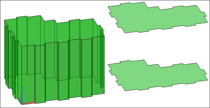
- Create two layers:
3D-SLABand3D-ROOF, colors at choice. Activate the first one. - Apply the
EXTRUDEcommand to the lower copied face, with height-0.3. - Activate the
3D-ROOFlayer and apply theEXTRUDEcommand to the upper copied face, with height15. - With
SOLIDEDITand the Body/Shell option, make the main solid hollow. Select this solid, remove both horizontal faces, and specify thickness0.3: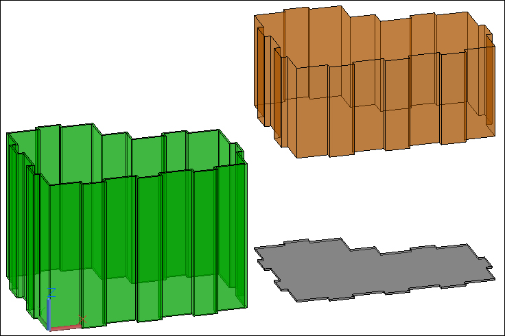
- With
SOLIDEDITand the Face/Offset option, offset all the roof vertical faces to the outside to make an eave. To easily select these faces, mark one, apply the All option, and then the Remove option, to remove both horizontal faces. Specify the offset value0.4. - To finish the roof, apply
SOLIDEDITand the Face/Taper option. Select again all vertical faces; the taper axis is defined from a bottom vertex to the projected upper vertex, and specify the angle45. If it gives a modeling error, try with another pair of vertices.
- Make the roof hollow with
SOLIDEDITand the Body/Shell option. After selecting the roof, remove the bottom face and press Enter. - Move the roof and slab back to its position, that is, a displacement of
40along the negative X axis. - The other slabs are shorter, so create one copy of the existing slab, shorten it by offsetting the vertical faces, and create the remaining copies. Now, copy the slab
3units along the Z direction. - Isolate this slab (select it, right-click and choose Isolate | Isolate Objects). Then apply
SOLIDEDITand the Face/Offset option, offset all the slab vertical faces with the value-0.3. End isolation. - Finally, copy this slab seven more times with the same distance,
3, along the Z direction. This is the easiest way to apply theCOPYcommand, Array option, eight elements, and distance3.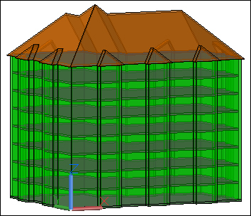
- Save the drawing with the name
A3D_07_05FINAL.DWG.
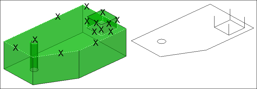
The following are two commands that create linear objects from solids or surfaces.
The OFFSETEDGE command (no alias), available since Version 2012, allows us to create a polyline or a spline parallel to the edge of a planar face of solids or surfaces. By default, the command prompts for the face and a point where it will pass the new linear object.
The command displays the default corner value and prompts for a planar face selection:
Command: OFFSETEDGE
Corner = Sharp
Select face: Selection
Then, by default, it prompts for a point where the new linear object will pass. It can be outwards or inwards, related to the face's edges:
Specify through point or [Distance/Corner]: Point
The face selection and point prompts are repeated until the Enter or Esc key is pressed:
Select face: Enter
This command has the following options:
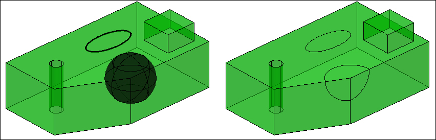
The SURFEXTRACTCURVE command (no alias), which is new in Version 2013, allows us to obtain curves (isolines) from surfaces or solids. The new objects can be lines, arcs, polylines, or splines. The command starts by displaying the default value of the Chain option and prompts for the selection of one surface, solid, or face:
Command: SURFEXTRACTCURVE
Chain = No
Select a surface, solid, or face: Selection
Specifying a point over the surface creates a curve. The prompt is repeated until the command is ended:
Extracting isoline curve in U direction
Select point on surface or [Chain/Direction/Spline points]: Point
Extracting isoline curve in U direction
Select point on surface or [Chain/Direction/Spline points]: Enter

This command has the following options:
- Chain: With this option on, the isolines are also obtained from adjacent faces in the same direction.
- Direction: This option allows us to change the direction of isolines, between
UandV. - Spline points: This option allows marking points on the surface and creating a curve that passes through all points. This curve does not respect the
UorVdirection.
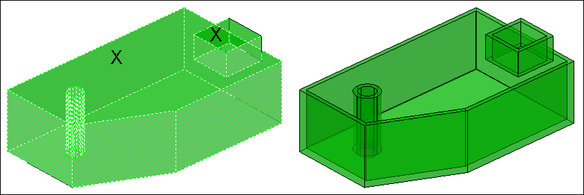
These two commands allow creating edges on solids or surfaces.
The PROJECTGEOMETRY command (no alias), available since Version 2011, allows you to project points and linear objects on solids and surfaces. This projection may cut the solid or surface. The command starts by displaying the value of the SURFACEAUTOTRIM variable and prompts for the selection of curves or points to a project:
Command: PROJECTGEOMETRY
SurfaceAutoTrim = 0
Select curves, points to be projected or [PROjection direction]: Selection
After the selection of objects to be projected, we select one solid, surface, or region:
Select a solid, surface, or region for the target of the projection: Selection
Finally, we specify the projection direction between the viewing direction, the current UCS, or by marking two points:
Specify the projection direction [View/Ucs/Points] <View>: Option

The command has the following option:
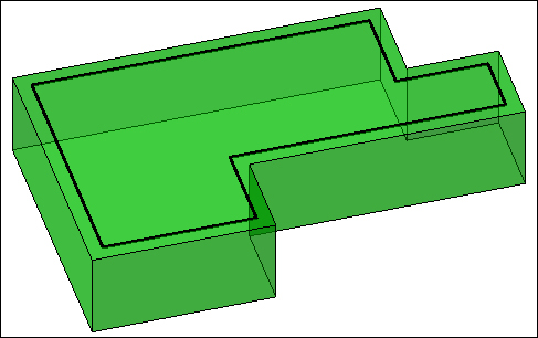
We are going to create a plastic part, with the application of the last seen commands.
- Open the drawing
A3D_07_06.DWG. This drawing is only composed by 2D polylines. - Start by orbiting the model and moving the inner polylines
30units along the Z direction. - Apply the
EXTRUDEcommand to the outer polyline, height of extrusion,5. - With the
FILLETcommand, round the bottom edges with a radius of2. The Chain option can be used to select all edges.
- To create a small wall on the top part, start by applying the
OFFSETEDGEcommand, selecting the top face, the Distance option, value3, and a point on the inside. A polyline is created at a distance of3units from the edge. - Apply the
PRESSPULLcommand to create the wall. We Specify a point between the edge and the polyline and height of extrusion,10. - Before projecting the small polylines, you must verify that the
SURFACEAUTOTRIMvariable is set to1. - Finally, apply the
PROJECTGEOMETRYcommand, selecting all small polylines, then the solid and the UCS option. All polylines are projected onto the solid, cutting it. - We may erase or hide the small polylines.
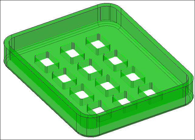
- Save the drawing with the name
A3D_07_06FINAL.DWG.