
When starting AutoCAD, the drawing area is composed of a single viewport where we create, view, and modify the drawing or the 3D scene. As the project advances, it may be useful to divide the drawing area in more viewports so that we can simultaneously view different parts of the model (for instance, a bridge drawing, where we want to see both extremes) or view it from different angles. We can start a command in one viewport and end it in another. As against the layout viewports, viewports in model space never overlap and completely fill the drawing area. Any model modification will be reflected in all viewports but visualization tools are independent. We can have viewports with different zooms, pans, orbits, or orthographic views, with different visual styles, perspective, or parallel modes.
The viewport controls, available in AutoCAD since Version 2012, are the three top-left menus for each viewport.

These viewport controls represent easy processes for controlling multiple visualization parameters already seen in this chapter:
- The [-] control: This viewport control controls the viewports' configuration and activation on visualization tools such as the ViewCube tool and the less used SteeringWheels or Navigation Bar.
- The [Top] control: This viewport control specifies the view direction between the saved, orthographic, and isometric views. It is also used for applying the
VIEWcommand and toggling between parallel and perspective modes. - The [2D Wireframe] control: This viewport control specifies the visual style, and is also used for accessing the
VISUALSTYLEScommand.
The
VPORTS command (no alias) allows you to configure viewports. It displays a dialogue box with two tabs:
- New Viewports: The New name field allows you to name the configuration; Standard viewports includes all possible configurations, and the preview is displayed on the right-hand side; Apply to specifies if the chosen configuration is applied to the drawing area or to the current viewport; Setup specifies if the configuration is 2D or 3D, the last applying immediately different views. Selecting each viewport in the Preview area, it's possible to change the view and visual style.
- Named Viewports: This tab just lists and previews the named viewport configuration.

Single configuration restores a single viewport in the drawing area.
Viewport configurations can also be accessed on viewport controls, on the Viewports toolbar, the Viewports menu bar in the View tab, and on the ribbon's View | Model Viewports panel.
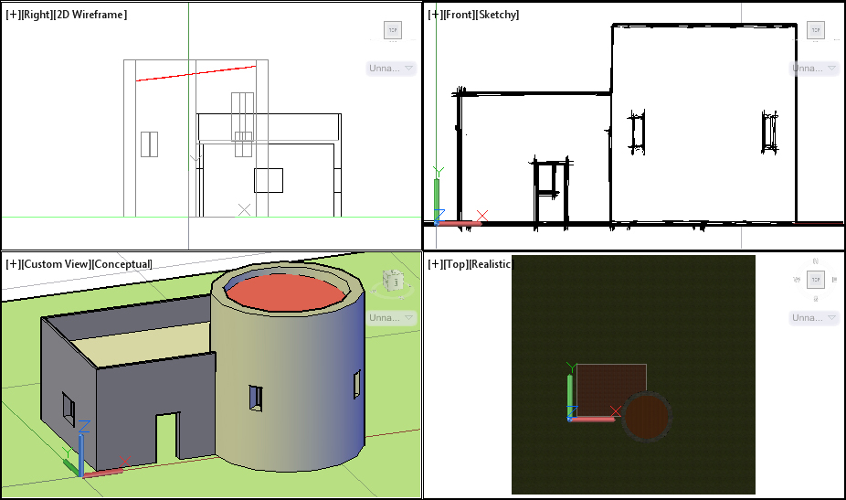
We are going to divide the drawing area, set different views, and save this viewport's configuration.
- Open the file
A3D_02_05.DWG. - Divide the drawing area into four viewports. Apply the
VPORTScommand and choose the Four: Equal configuration. On the Setup option choose 3D. In the Preview area, select View:*Right* and change the visual style to 2D Wireframe. Apply the Realistic visual style to Top and the Sketchy visual style to Front. - Still within the dialogue box, select View: SE Isometric and change the view to *Current*. Name this configuration My Viewports and click on the OK button.
- Adjust the zoom and pan in each viewport.
- Apply the
-VPORTScommand and select the Toggle option. We come back to a single viewport. - Quit the drawing without saving.