
Polymeric seals
7.1 Introduction
Small bore polymer tubing easily absorbs movement, but many conventional piping systems in steel or other rigid materials are still widely used for fluid transport. Yet they too need a way of sealing the system reliably in the face of vibration, especially where they join dissimilar materials. The answer is to close the system with a flexible polymer, and seals are of great importance in all engines and machines with moving parts (1). Sealants serve a similar purpose where gaps in a building, for example, must be closed against ingress of rainwater.
Seals have been critical parts of engines ever since the invention of the steam engine by Savery, Newcomen and Watt in the early part of the Industrial Revolution, with natural materials such as hemp fibre, leather and bitumen, for example, being used. The failure of such seals in Brunel’s famous atmospheric railway highlighted the importance of reliable materials which could not be consumed by rats or degraded by the environment (two of the problems with Brunel’s seals). It was discovery of vulcanization by Goodyear in 1844 which gave to the world a path to a better material capable of absorbing movement and vibration (2), a step heralding the invention of the humble O-ring and all manner of seals of different shapes and dimensions. Many new elastomers were developed in the 20th century such as polychloroprene (one variant being known as Neoprene), fluorinated rubber (such as Viton) as well as general purpose rubbers such as NBR (so-called nitrile rubber) and SBR (styrene butadiene rubber). Polyurethanes have also been developed both as cross-linked rubbers and thermoplastic varieties for sealing purposes (3).
We rely on such small components as seals of all shapes and sizes to keep cooling systems, heating networks, pneumatic lines and all kinds of engines operational so it is important to be aware of the failure modes of seals. A brake seal is a good example of a safety-critical seal, which, should it fail when driving, can cause a serious accident through total loss of braking power.
In manufacturing industry, air lines are an important way of transmitting energy, as the ABS pipeline in the previous chapter showed. But they are also used for controlling the manufacture of another important device, the semi-conductor, universally used in electronics in an application not usually appreciated. Failure of seals in such lines can curtail manufacture with large consequential losses unless simple precautions are adopted. Similarly, seals in hot water central heating systems are crucial in preventing leakages from the pipes, and if a new material is introduced, it must be capable of resisting both water and high temperatures. Testing such materials before use is essential, and only under conditions which are realistic in their simulation of reality.
Sealants, mastics and grouts are also used extensively in buildings to prevent entry of water from the environment, or in specialist applications, one of which includes special non-toxic smokes used to simulate fires in training buildings for the fire brigade. Such sealants must be able to resist the organic components of the smoke but if otherwise, real fires can result. Again, realistic testing is essential if those grouts or mastics are to provide a reliable sealing action.
7.2 Failure of elastomeric seals in brakes
Seals are needed in braking systems to isolate the hydraulic fluid from the mechanical load activated by the driver when attempting to slow the vehicle while driving. Loss of braking power is very serious while driving and can cause accidents, as the case presented in this section shows. The case was referred from insurers in 1982 in relation to a serious accident with a van which had been involved in a crash. The rear brakes had failed, leakage of brake fluid having been found when the vehicle was examined after the accident. The van had travelled about 10 000 miles between fitment of the brake cylinder and failure.
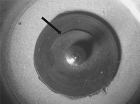
When the brake cylinder was removed and stripped, it was found that a small piece of rubber had broken away from the lip seal which isolated the hydraulic circuit (Fig. 7.1). The small chip was roughly ellipsoidal in shape and had broken away through the lip of the seal where hydraulic pressure from the brake fluid pushed the edge of the lip into contact with the sides of the brake cylinder. The seal appeared to be under-size, judging by the gaps at both top and bottom in the recess within which it lay. It was also interesting to observe that there were also gaps between the edges of the chip and the fracture surface in the bulk of the seal (left-hand picture of the figure). Inspection of the opposing fracture surfaces showed numerous striations characteristic of a fatigue failure (Fig. 7.2).
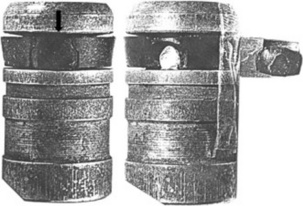

The piston had a diameter of 19 mm and sat within the cylinder of bore 19.06 mm, so the seal had a gap of 0.06 mm to fill when in position.
7.2.1 Scanning electron microscope (SEM) of fracture surface
The sample needed more detailed examination in a scanning microscope. It was cut vertically along the side opposite to the fracture so as to separate it from the aluminium die-cast piston of outer diameter 19 mm and length 48 mm. The seal sat in a recess of diameter 12.15 mm in the end of the piston. The diameter of the seal shrank by about 1 mm when removed, showing that the seal was under tensile strain when in situ, in addition to that already noted on the mismatch between the chip and the seal (Fig. 7.1). So the original strain in the unbroken intact seal was likely to have been greater owing to relaxation of the seal by its fracture and by removal from the piston.
It was coated with a thin layer of gold to enhance contrast and reduce the chances of a build-up in charge on the non-conducting surface of the rubber. The nearly complete fracture surface from one side of the fracture in the seal is shown in Fig. 7.3. It shows progressive growth of a brittle crack from the outer corner of the seal up through the body until it met the channel to the lip and grew further to the free surfaces so as to form a separate chip. The direction of crack growth can be judged by the flap formed at the top of the sample by the crack branching just before it met the outer free edge. The other half of the fracture surface showed a similar pattern of the striations from the corresponding outer corner of the seal.

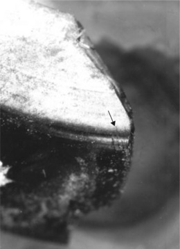
So what had initiated the two separate cracks? Deep cuts were found at the lower outer corner of the seal (Fig. 7.4) and there were matching scratches found on the outside of the piston on the land adjacent to the seal recess (Fig. 7.5). Inspection of the interior of the cylinder in which the piston worked also showed traces of similar scratches (as well as a tide mark from the resting position of the rubber seal). However, there was no trace of any particles left in, or on any of the samples. It seemed clear that contamination by sharp abrasive particles had caused significant damage to both the piston and the seal it held.

7.2.2 Elastomer analysis
The material of the seal itself was analyzed by exposing the rubber to several different organic solvents, and the swelling measured and compared with known standards (4). Since different rubbers swell to different extents in organic fluids, the particular swelling properties are diagnostic of a specific elastomer. One way of identifying different cross-linked rubbers is by comparing the swelling in three solvents: petroleum ether, benzene and aniline. A small sample of regular section (such as strip) is exposed to the solvent until swelling ceases (usually several hours), and the swelling calculated from the change in dimensions. The closest match to the brake seal values was found to be SBR rubber, a general purpose elastomer widely used in car tyres, for example.
Although such a swelling test would now be difficult, since benzene is barred from laboratories as a known carcinogen, swelling tests with other more benign reagents are still useful as diagnostic analytical tool. However, such identification tests have been displaced by IR spectroscopy using ATR (attenuated total reflection) where a sample is pressed against a selenium crystal and the spectrum obtained by multiple reflection of the beam.
Using SBR in brake seals is unusual because it has poor resistance to oils and might explain why the seal appears to have shrunk in its recess (Fig. 7.1). For example, SBR is usually plasticized with extender oils, and these can be leached from the material by brake fluid. If that had happened, then the volume would shrink, as seems to have occurred. With shrinkage comes an increase in tension or hoop stress in the circumference of the seal, also seen both in the fracture and when removing the seal from the piston. Finally, SBR has poor resistance to fatigue, and much lower than natural rubber, for example (4).
7.2.3 Explanation of accident
The direct cause of the failure of the brake seal was abrasive cuts in the outer corner, probably caused by sharp particles which contaminated the fluid. They initiated two fatigue cracks, which grew steadily with use of the brakes on the van. Each application of the brakes by the driver will have imposed an extra hydrostatic stress on the seal. When the brake pedal is pushed down, a lever pushes against the piston, which in turn pushes against the closed hydraulic system. The pressure developed in the fluid acts against the seal lip, pushing it against the walls of the cylinder, but also putting the entire seal under pressure. The hoop stress thus increases throughout the seal, and will be concentrated further at stress concentrations, especially deep cuts (effectively proto-cracks).
It is possible that the cuts were formed when the piston and seal were first installed, so growth occurred from first use of the brakes. The net stress at the roots of the two cracks involved was a product of fitment and the start of shrinkage produced by extraction of the extender oil. Growth will have been slow at first, and dependent on the degree of braking used by the driver.
A critical point was reached when the cracks reached the base of the lip channel. Slow leakage of brake fluid will have started at this point, the rate of leakage being very slow, since the crack opening will have been very small (and the viscosity of the brake fluid being very high). However, that rate will have increased as the cracks grew into the lip of the seal. The van mileage of 10 000 clearly represents high usage but the nature of that driving was unknown: motorway driving will have involved much smaller brake use than urban driving, for example. When the van was serviced, the brake reservoir probably needed topping up, but clearly the state of the seal was not examined. At the same time as fluid leaked out, air probably entered the system, making the brakes feel ‘spongy’. Air is highly compressible, so pedal pressure will compress the air first and then the brakes, reducing the efficiency of the system.
The next critical point was reached when the two cracks met and formed the chip, and brake fluid will have leaked copiously at this point, with total loss of braking to the vehicle from the open cracks (Fig. 7.1). It could well have occurred when maximum pedal force was applied by the driver in an emergency.
The root cause of the failure was a poorly designed brake seal, which was probably contaminated at fitment by sharp particles; the particles cut the edge of the seal and started two fatigue cracks which grew to completion. Great care is needed during all vehicle maintenance to ensure the correct size and type of seal is chosen by the mechanic. In any case, the driver should have been alerted by sponginess in his brakes, and asked for the brakes to be bled and thoroughly examined for any defects. The replacement seal was quite different in design, with no lip at all, suggesting that the original may have been a simple mistake by the mechanic. Whatever the cause, there was no epidemic of brake failures, so the failure must be put down to human error and poor maintenance.
7.3 The Challenger disaster
That seals are frequently critical parts of many devices and machines was brought home to one of us (PRL) during routine domestic maintenance. He had been puzzled by the failure of a shower head attached to the hot and cold water supply in his bathroom. Demands from other users, especially his daughter, prompted an investigation. When the joint between the water supply and the head was disassembled (with great difficulty owing to build-up of calcium carbonate from the hard water), he found that an O-ring had jammed inside the valve, and was blocking the pipe. The previous owner had fitted an oversize ring, which then extruded under pressure and blocked the valve. The solution was simple: to remove and replace with the correct size ring. But there may be other problems with O-rings, especially their behaviour at low temperatures when fitted to rocket casings exposed to external temperatures.
And that is just what happened when the Challenger shuttle exploded shortly after take-off from Cape Canaveral on 28 January 1986 killing all seven crew aboard. It was not so much the shuttle itself, but rather one of rockets used to boost it into space that exploded, and NASA had been warned that there might be a problem. Film of the disaster showed that just before the final explosion, a jet of flame issued from one of these joints on one side of one of the two booster rockets. It had failed to contain the burning contents, and the gap grew as the joint eroded away, ending with an explosion which threw the Challenger into the sea below (Fig. 7.6).

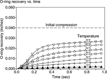
The rocket concerned was made from several steel cylinders which were united at their ends by special joints. A key part of the seal between the two cylinders was a set of two Viton fluoroelastomer O-rings of diameter 0.28 inches (5 mm) set into the inner side of the joint (Fig. 7.7). The joint was further protected from the effects of the hot propellant by insulation and a seal of zinc chromate putty. The elastomer of the O-rings is resistant to high temperatures, but that resistance drops rapidly as the temperature falls below ambient. And there had been failures of the rings in previous tests, which gave warning of this, the weakest part of the structure. The problem can be appreciated by considering the effect of internal pressurization as the propellant ignites and starts to burn during lift-off (5). The pressure forces the steel cylinders to expand well away from the joints, so bending the joint in the opposite direction (Fig. 7.8). It opens a momentary gap on the inner side, and the rubber of the O-rings must fill that gap in the fraction of a second to maintain the integrity of the seal.


As was pointed out by Richard Feynman at the subsequent official enquiry, just immersing a sample of the rubber in ice water was sufficient to reduce its resilience so that an O-ring could not react quickly enough when stressed (6). This is the crucial property needed in a rocket casing O-ring, because it must maintain the seal when the joint is vibrated by the forces exerted on the outer casing by combustion processes within the rocket. The response time of the elastomer decreased very rapidly as the temperature fell (Fig. 7.9), and freezing conditions had occurred overnight at the launch site. Indeed, there was some evidence that water had penetrated the field joint, further compromising its integrity. Needless to say the entire joint has been redesigned to incorporate extra O-rings, and rigorous tests have ensured that joints have behaved correctly during launches of the shuttle.
The disaster also revealed shocking lapses in management of the project. Engineers at Thiokol Corporation (manufacturers of the rockets) had warned NASA of the possible problem before the launch, and advised against a launch after the cold weather had been reported. However, NASA over-rode their advice and proceeded. Their negligence had a severe effect on the entire US space programme at the time and invigorated development of unmanned missions. The development of the shuttle, however, itself introduced further problems with the crash of the Columbia on 1 February 2003, when it disintegrated over Texas during re-entry into the Earth’s atmosphere, with the loss of all seven crew members (7). That disaster involved failure of polymer components, too, because it was afterwards found that a lump of polyurethane insulation on the exterior of one of the rockets came free during launch and impacted the wing of the shuttle. The impact created severe damage to the carbon fibre composite wing, which went unnoticed by the crew during their successful research in space. However, the damage was critical and the wing disintegrated during reentry. It was a failure of testing, because impact tests had been conducted using small lumps of insulation, but nowhere near the size of the large lump which actually caused the accident. As with the Challenger disaster, the events could be seen, albeit at very low resolution, on the videotape of the launch, but only after the event.
7.4 Failed elastomeric seals in a semi-conductor factory
The first notice we had of a failure in a pneumatic line came when a company representative visited us with a failed diaphragm seal. The rubber diaphragm seal in an air line had cracked and the company who had supplied it wanted diagnosis and advice on prevention of a recurrence of the problem. The seal worked in the air line at a semi-conductor factory in Japan, and closed a chamber supporting the air bearing of the main stage holding the chip (Fig. 7.10). A new rubber seal is shown from above and below in Fig. 7.11, and it is a critical component because the air bearing is dependent on the integrity of the seal. The air bearing ensures that the stage is absolutely motionless to enable accurate etching of the chip surface when making the chip circuitry. Since they typically are of the order of fractions of a micron in resolution, any vibrations or movements can wreck the quality of the chip. The seal was small, measuring only 10 mm in diameter, but sitting at the centre of a steel disc of diameter nearly 40 mm. The seal was 2 mm thick and the membrane 0.5 mm thick.


7.4.1 Failed diaphragm seal
The failed seal is shown in Fig. 7.12. The damage included erosion of the edge and fine cracking of no apparent preferred orientation next to the hole that accepts a steel axle when in position on the etching machine. It was made of NBR, or nitrile butadiene rubber, which is a copolymer of acrylo-nitrile and butadiene monomers:

Its composition varies between 15 and 30% acrylonitrile, the latter groups providing oil resistance to the butadiene elastomer. The homopolymer polyacrylonitrile is a fibre forming polymer known as ‘acrylic’ as well as forming a thermoplastic material in SAN or styrene-acrylonitrile. The butadiene content gives the material elasticity but is also most vulnerable to oxidation via the double bonds in the chain. Carbon black filler provides some limited protection but the material is vulnerable to degradation. The damage looked like oxidative attack and erosion, perhaps during manufacture, and the company were advised to check the conditions under which the seals were made. The state of the new seals supplied for purposes of comparison also showed manufacturing defects such as weld lines, probably produced by poor temperature control of the steel tools used during compression moulding the devices (Fig. 7.11). The same picture also shows excessive flash rubber near the central hole, as seen on the lower surface of the seal at left in the figure.
7.4.2 More failed seals
But it was not the end of the story. A few weeks later, the same company came back with another problem. The seals were cracking in a different way, and this time, chip production had been lost since the air bearings had lost pressurization (Fig. 7.13). Several seals were affected, so production on etching machines was lost. The attack was highly localized with a single circumferential crack with a very rough fracture surface (Fig. 7.14). It turned out that it was not the only rubber part involved. O-rings used to seal other parts of the machines were also failing (Fig. 7.15). Cursory inspection with a magnifier showed characteristic brittle cracks running across the diameter, one of which had run to completion. The ring shown had a diameter of 2.5 mm and a circumference of 70 cm, and fitted a large seal between chambers in the same pneumatic system.


It was clear that a detailed investigation would be needed to pinpoint exactly the nature of the cracking in the diaphragm seal in view of the loss of chip production. The first step was to examine the seals using ESEM, a method of high enough resolution to reveal the characteristic crack features which might point to the cause of the problem. It was also a method ideally suited to examining such a small component, the size of which would challenge the skills of an optical microscopist.
The very first low magnification pictures did indeed reveal that the crack had grown along a sharp inner corner of the seal (Fig. 7.16), and a sub-critical crack was also present at the corresponding inner corner close to the axis of the product (Fig. 7.17). Both corners represented stress concentrators, and were the most likely to be attacked if the diaphragm was subjected to only small pressures. The membrane between the two corners was only 0.5 mm in thickness, so only a very small degree of cracking could cause total loss of function. The main fracture surface was rough and showed no inner structure (such as striations) and was very similar to that previously seen in the optical microscope (Fig. 7.14). The inner sub-critical crack appeared to show a tendency to branch into the membrane, perhaps caused by breakage of the membrane at the outer corner, putting a small bending moment on the membrane.


One advantage of ESEM is the facility to perform X-ray analysis, and comparison of the elemental composition of the crack and an intact surface showed that the crack had a higher oxygen content than unaffected rubber (Fig. 7.18). Such evidence pointed to ozone rather than oxygen attack, a well-known failure mode of many elastomers (all those containing double bonds).

7.4.3 Ozonolysis
Ozone gas is an allotrope of oxygen, and one of its most active forms because the gas attacks organic materials by way of their double bonds, which it cleaves very quickly:
In this generic example, ozonolysis produces an aldehyde and a carboxylic acid group at each of the new chain ends, so accounting for the increase in oxygen content of the crack surfaces. But the most important effect is to break the chain:
In this case, the chain is broken twice, and since the strength of polymers is critically dependent on chain molecular weight between cross-links, the strength drops and cracks develop (8-11).
In surfaces attacked by ozone, one would therefore expect to see higher levels of atomic oxygen from the aldehyde and carboxylic acid chain ends left after ozone attack (12, 13). In fact, in an elastomer like nitrile rubber, there is no atomic oxygen present at all in the pure polymer, but various process aids such as stearic acid and its salts are used in commercial materials. Since such acids or esters do contain oxygen, it will be found in the ESEM spectrum, so the extra oxygen produced by ozonolysis will enhance the relative amount found, as observed (Fig. 7.18). That salts were present can be judged by the trace amounts of several metals found in the seals, such as calcium, magnesium, zinc and aluminium.
7.4.4 Independent analyses
The semi-conductor factory was situated near the east coast of Japan, and gas analyses were conducted by the company on the air supply system itself. It was achieved by conventional chemical means, and provided a clear picture of the state of the air in the pneumatic system. The semi-conductor line comprised, at least in principle, four branches, each of which had four machines (Fig. 7.19). But only eight machines were being used, the other positions being empty pedestals. The diagram shows that seven of the eight machines had been affected, the largest number of seal failures having occurred on the machines present on the first two branches, while the apparently unaffected machine was at the end of its branch, at the furthest end of the air supply. It suggested that whatever was causing the damage was being exhausted by attack. This is just what happens during ozone attack, as shown by the equations above, that ozone is absorbed by the rubber, and will be depleted further along in the system. Failures tend to decrease along each branch as the gas is absorbed.

The two points where analyses were taken are shown in Fig. 7.19, with samples from the first branch. The sequence of failures is shown in Fig. 7.20, with the first being obtained in January 2001 and building up progressively in many different rubber components as the months passed. Thus although by the middle of the year, the failures had appeared to cease, they suddenly started again in earnest by early 2002. The failures had occurred over a wide range of different seals (as shown by the symbols) and were also occurring at a lower level in the apparently unaffected machines, which are identified by their numeric code in the table.

The results of analysis are shown in the table (Table 7.1). It shows the concentrations of ozone and nitrogen dioxide (NO2) at the level of parts per billion (PPB) and also expressed in nanogrammes percubic metre of the air in the system (ng/m3). The table compares the concentrations in two quite separate lines in late 2003 when the crisis was at its height, the lower part of the table showing that the gases were effectively either absent or at minimal levels in the Canon line compared with the ASML line. The levels of ozone were at a maximum of 2.7 PPB down to 0.9 PPB and varied between these two values over the period in which measurements were taken. The levels of NO2 appeared to parallel those of ozone, although the association was not strong.

So these results when taken together confirmed that ozone was the cause of the problem, but what could be the source of the gas in such an enclosed system? And secondly, why had the problem only started recently?
7.4.5 Sources of ozone
The investigation now turned to a more detailed examination of the pneumatic system itself and possible sources of the gas. In general, ozone is produced in several different ways, including (14):
The association between electrical discharge and ozone is strong, since it is known that ozone is produced during thunder storms when lightning occurs (15). The passage of large high-energy sparks through the air causes a cascade of reactions between oxygen and nitrogen, including the creation of nitrogen dioxide and eventually nitric acid when it reacts with water. But the same extremely high temperatures also create ozone, and are present even in small sparks often present near electrical machinery. And visible or audible sparks are not the only source of the gas because silent discharge of static electricity, for example, can also create the gas. Thus high concentrations can be found near xerographic photocopying machines, and indeed wherever discharges can occur either as a part of a process, or accidentally by leakage of electricity.
The final source of the gas is by photochemical interaction between the energetic UV component of sunlight and the atmosphere, especially when volatile organic components (VOCs) are present (16). The most common VOCs are those produced by vehicle engines, both diesel and petrol powered, including traces of those fuels and their combustion products in exhaust fumes. It leads to local pollution and, when bright sunlight shines on the mixture, to the formation of ozone and nitrogen oxides (NOx). The problem thus occurs most frequently in or near city centres, and many cities around the world suffer such gaseous pollution. Examples include The Los Angeles basin in the USA and Mexico City in the Americas, but it is also a problem faced by many other developed cities like London and Paris as well as cities in the developing world such as New Delhi, Shanghaiand Beijing (17). And such polluted air can travel some way before it is removed either by interaction with unsaturated organics or washed from the atmosphere by rain, for example.
7.4.6 Chasing the problem
So one line of attack on the problem examined the local atmospheric conditions near the factory in Japan, while another lay in examining equipment at or near the air intake: the compressor and associated filters (Fig. 7.21). The compressor itself was apparently a conventional design of rotary pump using oil, so the filters fitted to the output gas were designed to trap any oil droplets that accidentally entered the compressed air supply. This was also why the elastomeric seals were made from nitrile rubber, a material well known for its resistance to oil. None of them would react with ozone, however, so the compressor could be the source of the problem, once external pollution had been eliminated. Despite an extensive review of the atmospheric pollution in the mainly rural environment, there was no convincing evidence to show that the gases were present in air sucked into the system from the outside. Indeed, such was confirmed by analysis of the air intake using the chemical methods used for the line itself.

The composition of the gases present in the system at various times in late 2003 (Table 7.1) suggested an electrical source, since high levels of NO2 and O3 seemed to occur together. A local and nearby source was the most likely explanation, either close to the air intake or within the compressor itself. The electrical motor driving the compressor could not be the source, since the workings were totally independent of the gas line, so another explanation was sought.
On detailed examination, it was found that the compressor had itself been changed on the line recently, from a conventional rotary type to a new design which used counter-rotating helical rotors to create the air pressure. The space between the rotors gradually decreased so that the ‘nip’ between the two rotors slowly diminished, and so the air pressure rose (Fig. 7.22). The rotors themselves were plastic-covered so as to ensure a smooth air flow, as well as protecting the polished metal surfaces. Now when non-conducting polymers are used in such a way, the chances of static electrification arises. Many plastics when rubbed physically can produce high local charges, which cannot leak away easily through the bulk, since the materials are insulating by their very nature (18). Such triboelectrification (as it is called) is commonly encountered in dry atmospheres, where leakage through the air is also hindered. The phenomenon can, for example, cause sparks to be generated when a driver steps from a car owing to triboelectrification by tyre contact with the road with the charge building up on the metal car frame acting as a Faraday cage. Even removing a nylon shirt can generate small but very powerful sparks.

It was therefore the likely source of the problem in producing tiny amounts of both ozone and nitrogen dioxide in the air supply, the gases attacking and slowly cracking the crucial diaphragm seals. The solutions to the problem were several. They included changing the elastomer of the seals to an ozone-resistant material like Viton or EDM, or installing ozone absorbing filters after the compressor (especially those containing activated carbon, a very effective absorber). A recommendation to remove the stress concentrating corners by rounding off the tool was also made as a sensible precautionary measure to reduce the possibility of cracking (Fig. 7.10).
Such filters were introduced and the seal corners radiused, so eliminating the problem at source. We were sent samples from another lithography line shortly afterwards, where similar cracks were found. Pro-active maintenance had given the manufacturers fair warning of the problem. However, the cracks had not grown to completion and another series of failures was prevented before they could cause production problems.
7.4.7 Conclusions
So what were the lessons of the incident? In the first place, the cracking had a severe impact on the normal operations of the semi-conductor factory. Each time a seal cracked, chips were destroyed during their production, and the line had to be halted while new seals were installed, so causing consequential losses in production, which were estimated to be costing the company $1.5 million per week, such is the level of investment in the lithography machines. The costs of prevention were trivial by comparison.
The problem might have been circumvented by using a more resistant rubber, but the problems of new compressors were clearly totally unexpected. And it is surprising to learn that tiny concentrations of ozone can have such far-reaching effects on items that nobody assumes can fail. The reason why ozonolysis can be so devastating is the almost quantitative reaction with double bonds, and indeed, has been used widely in analysis of organic compounds for structure determination because if the products are analyzed and identified, it is then possible to predict the starting structure. The reaction can also be turned around to another useful function: detecting small levels of ozone in a gas by simply suspending rubber bands and counting the number of cracks and their shape as they are formed.
So despite the fact that most seriously stressed elastomeric products are nowadays well protected against ozone attack (and oxygen, too), there may always be safety- or function-critical components waiting to fail because no one considered ozone attack at all likely.
Ironically enough, another Japanese company had alerted the industry to the potential problem of ozone attack in 2001 (19), but few were apparently following or reading the relevant literature. The report was made by SMC of Japan, one of the largest manufacturers of pneumatic equipment in the world, who posted it on their website and so made it available to everyone at the time. The document provides examples of cracked seals of all kinds, and describes the problem of the presence of only trace amounts in a pneumatic air supply system. Sources of the gas are discussed thoroughly, and the specific problem of scroll compressors mentioned as a particular problem. They manufacture a range of seals where the problem is suspected, using ozone-resistant elastomers.
The importance of reviewing available literature is one of the themes in many of the case studies discussed in this book: a new problem may just be a recurrence of one that has happened before, then buried and forgotten until the next outbreak. But the availability of relevant information has changed out of all recognition with the world wide web. Vast amounts of data can be accessed both on commercial websites as well as in the academic literature with the use of appropriate key words. Much information is also of course available in conventional text books, although specific failure cases are often difficult to find, perhaps owing to a natural reluctance to reveal embarrassing results. Text books are also frequently out-of-date, and often do not cover as many areas of technology as would be desired. The SMC decision to post details of their experiences (clearly based on their own failures) is heartening, and one hopes that other companies working in other areas of technology will follow suit.
7.5 Failures in TPE radiator washers
Washers are another type of seal where function and performance are critical to the integrity of the system in which they operate. Central heating systems (CHS), for example, are almost universally used today in most domestic and public buildings, replacing less efficient open fires for providing reasonable warmth throughout the winter months as well as a convenient source of hot water for baths and kitchens. The hot water heated in a boiler is distributed to metal radiators located in every room, to provide space heating, such water being circulated in a closed system topped up when necessary by a cistern. The same supply is also sent through a copper reservoir to heat water for direct use by the consumer.
Such systems must be sealed effectively against leakage through the many joints needed on the extensive copper pipework, including seals on the radiators, for example. If such seals leak, then consequential damage to property can be extensive if not detected in time. Various materials have been used by plumbers, including winding fibre around the pipe end, which jams into any gap in the joint. PTFE tape has also been used in a similar way. Rubber washers made from conventional cross-linked materials are also widely used on taps. But such seals do suffer significant problems, fibre and tape often leaking slowly due to small gaps present on formation by crushing the material into the joint. Conventional rubber washers deteriorate with time, especially when exposed for long periods to high water temperatures, by oxidation and cracking, leading to leakage.
In an attempt to address these problems, a plumbing supplies company in the West Midlands experimented with thermoplastic elastomers or TPEs, a relatively new class of rubbers that have become available over the last two decades. Their use in catheters was described in a previous chapter, for example. As that case study showed, however, their physical and chemical properties must be thoroughly explored when being introduced into the market. The present case reinforces that very basic message.
7.5.1 New washers
One of the big advantages of TPEs lies in their ease of manufacture using injection moulding rather than transfer or compression moulding for conventional washers. Very large quantities could be made quickly using multiple cavity tools, cutting costs. Waste polymer can also be recycled, while conventional rubber waste must be scrapped. So the company proceeded to trial washers made using polyester TPEs, a block copolymer of polyester and polyether (Fig. 3.2). The former blocks crystallize to reinforce the elastomeric network of flexible polyether chains, so providing stability to any products. The trials showed that such washers worked well in both cold and hot water taps, so the company proceeded to adopt them for use in central heating systems.
7.5.2 Leaks in CHS systems
However, leaks were detected by several users after a few months, especially local authorities who had new CHS systems recently installed in schools and old people’s homes. A private school, Benenden, in Kent, also reported failures of washers and leaks, damaging nearby furniture and fittings such as carpets. Figure 7.23 shows the upper vent plug on one such radiator. The radiator came from Stratford old people’s home. Failures were being reported across such a wide range of installations that a thorough investigation was needed, and the loss adjusters instructed forensic engineers. Their report concluded that the washers had been damaged by plumbers over-tightening the joints, or alternatively, the joints were not tightened enough. Although plumbers can make mistakes, the failures suggested widespread incompetence by many different plumbers, an unusual and noteworthy situation. The insurers (via solicitors) approached us for an independent assessment of the problem as the matter had proceeded to a court action.

Our first task involved direct examination of failed joints, and it quickly became obvious that the first investigators were mistaken. Failed washers taken from the leaking radiator from Stratford were clearly cracked across their sections (Fig. 7.24). Indeed, when another washer from the first investigators was examined, it, too, showed severe cracking, cracks which were present when originally examined, as a reprint of the photograph from their report showed. The arrows in Fig. 7.25 mark the cracks in the washer as received and the reprint with an identical set of defects at right. The first investigators had completely ignored direct evidence of cracking, presumably in an attempt to reject the large claims for damages from the aggrieved consumers. Such biased reports are actually quite common, but increase costs dramatically by demanding re-investigation especially when litigation has commenced.


7.5.3 Simulation experiments
In fact, other failed samples showed a range of other damage, including extrusion of washer polymer around the joint (Fig. 7.26), for example. Perhaps it was this evidence that allowed the first investigators to accuse plumbers of over-tightening the plugs. Other failed plugs showed traces of white paint on joints, leading them to allegations of under-tightening because paint could only have penetrated the joint if a gap was already present (Fig. 7.27). But they had ignored alternative explanations, and specifically that the material had itself deteriorated. Another investigation by independent consultants at RAPRA used experiments on brand new washers to show that the polymer had indeed changed with time and temperature of exposure. Table 7.2 shows the results of several experiments designed to test the material for withstanding compression, just as it would when used in a radiator joint. Exposure of washers in plugs for 3 weeks at 85 °C (the temperature of the hot water in some CHS systems) showed a large reduction in the torque needed to unscrew the joint from 27 to 7 Nm.
Table 7.2
Exposure experiments for Hytrel washers (RAPRA)
| Experiment | Torque test | Hardness |
| Nm | Vh | |
| New washers | – | 3.9 4.3 4.1 |
| Plug and vent | 27 Nm to fit | 5.8 from vent |
| fitment | Mean of 7 Nm to undo after 3 week exposure at 85 °C | 6.8 from plug |
| Washer stacks (5 thick) | Compressed by 1.79 mm in total, original thickness of each washer 2.28 mm 2 Nm to release after 3-week exposure at 85 °C | 6.2 5.1 5.7 |


A stack of new washers showed a similar effect and, in both experiments, the hardness of the polymer had increased sharply (20).
7.5.4 Direct examination
These results were confirmed by quite independent estimates of the thermal properties of the polymer. Comparison of failed and new washers showed a substantial increase in the heat of fusion from 30.7 to 43.3 J/g of polymer, an increase of over 40% (Fig. 7.28). The result could only be explained by crystallization of the main hard blocks, the polyester segments in the chain network. That would explain the marked increase in Vickers hardness observed independently. There was virtually no change in melting point and little change could be seen by FTIR spectroscopy.

Optical microscopy of at least one fracture surface showed traces of striations (Fig. 7.29), a possible result of thermal stresses on the washers as the CHS system cycled between hot and cold conditions. But what could have caused the brittle cracking? It is true that crystallization will lead to stress in the washers as the material contracts, but cracking seemed an unusual response when, ordinarily, the polymer is tough and ductile. The cracks could not have been caused by a weld line because several cracks were seen on single washers (Fig. 7.25). Further explanation was needed.

7.5.5 Hydrolysis
When polyester TPEs were originally developed by DuPont in the USA (21), they were aware of the problem of hydrolysis of the material at high temperatures. They advised product designers to match conditions of use very carefully to the degradation of specific grades. They issued a technical advisory leaflet showing how the tensile strength half-life (defined as the time needed for the tensile strength of the product to reach half the value found in new products) varied with temperature of exposure (22). The graph they supplied for one grade of Hytrel showed the relation between temperature and tensile half-life, being a linear relation when plotted using log-reciprocal ordinates (Fig. 7.30). One of us (PRL) was involved in the original development of the material in 1968, when he showed that thermal degradation had inhibited formation of high molecular weight polymer. By redesigning the reactor, the problem was eventually overcome.
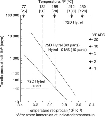
The specific grade shown (lower line) was similar to that used for the washers, and shows that at a continuous exposure temperature of 50 °C, for example, the tensile half-life is about 120 days, but drops to only 40 days when the temperature rises to 70 °C. The life time drops yet further as radiator temperatures rise further. But it might be objected that radiators are used intermittently and not continuously, so the washer life will be longer than the graph shows. There was, however, evidence from the sheltered accommodation that owing to the greater needs of senior citizens, radiators were kept at high temperatures for longer than is normal in most domestic situations. It would certainly explain why failures were first reported there. Damage was of course accumulative.
Cracks would have been started early in the lives of washers by chain cleavage through scission, a familiar mechanism studied in earlier chapters. Both polyesters and polyethers are known to be sensitive to hydrolysis, which is why they must be dried thoroughly before being subjected to the high melt temperatures involved in moulding. Hydrolysis is also enhanced by strong acids, and although radiator water itself is non-acidic, the reaction tends to be self-propagating, since acid is produced by hydrolysis. Once chains started to break, a fissure was created and hot water penetrated further provided hoop stresses were present to encourage crack growth. Only small stresses were needed, and they may have been present as a result of crystallization. Any compressive stresses present originally were reduced greatly by the process (Table 7.2), so it might be expected that crack growth occurred late in the failure sequence, maybe even as the washers were removed.
Whatever the detailed failure mechanism, the widespread installation of the polyester or Hytrel washers without testing was an unmitigated disaster, and all had to be replaced, with a large damages bill on top for those radiators which had allowed leakage to occur. The case did not proceed to trial since all the experts agreed on the basic causes, so court hearing costs were saved. The washers were eventually redesigned in EPDM elastomer, a polymer with intrinsic resistance to hydrolysis.
7.6 Failures in silicone mastics
Builder’s putty is a common everyday product, and has been supplemented by a range of other sealants for specific applications. Thus silicone mastics are used where water resistance is needed, and many other types have been developed using different polymers. The products usually consist of a polymer plus plasticizer and a filler such as calcium carbonate, or chalk. Builder’s putty itself consists of a blend of chalk and linseed oil, an unsaturated vegetable oil which slowly cross-links with time. The liquid reacts with oxygen in the air in a slow and predictable way to form a hard skin as the gas diffuses through the surface until the entire mass is hard and brittle. Brittle cracks become evident at a later stage in the process, so the glazing must be replaced because water can enter and initiate rot or rust of the frame. The glazing loses its ‘tack’ or stickiness owing to the depletion of unsaturated double bonds in the linseed oil chains, so is usually easy to remove and replace. Indeed, various grades of linseed oil are available where the reaction is speeded up, as in boiled linseed oil, and there are many other natural oils which have even higher rates of oxidation, such as tung and teak oils.
Mastics are used not just to provide a seal for windows, but in many applications where a seal against the environment is needed. And where that environment contains gases or fluids that can interact with the seal, there may be problems of seal deterioration and failure. So a mastic material must be chosen very carefully, and tests conducted to ensure that it will resist the environment it is intended to seal against.
7.6.1 Fire station training building
Fire brigades require staff to train for the many different problems which can arise during accidents, conflagrations, floods and other hazardous situations. Fires of course present some of the worst hazards, among which entering the smoke filled environment of a burning building can be considered one of the most dangerous. The London Fire Brigade erected a building at their Southwark headquarters for just such training, effectively a multi-storey shell which could be filled with a synthetic smoke, and which was equipped with a ducting system to spread the smoke into those parts being used during training. The ducting was made from pressed steel sheet sections joined conventionally by bolts, the joints being sealed with mastic to prevent leakage of smoke into those parts of the building where it was not needed.
The smoke was generated by heating a paraffin oil (23) to high temperature, and jetting a stream of nitrogen gas through the fluid to create an aerosol with oil droplets of 0.5 to 2 microns in diameter. The generator sat outside the building and smoke was ducted to various parts of the building when needed. However, the building suffered a real fire shortly after the building was completed. Smoke escaped and condensed on insulation nearby, where it caught fire, although there were no casualties. Such an embarrassing incident led to an enquiry, where the condition of some of the sealants was found to have deteriorated and allowed smoke to escape at an unexpected location. Proceedings were issued against the installers of the sealants, and we were asked to investigate in 2006.
7.6.2 Sealant analysis
The sealants were examined in situ at the building, and showed a wide variety of states. In one room, there were signs of the sealant running down the front of the ducting (Fig. 7.31), while an adjacent port in the ducting proved to be quite adequately sealed by a conventional cross-linked elastomer. Another seal elsewhere had, however, liquefied prematurely, leaving traces far from the original joint (Fig. 7.32). Samples were taken for further examination using infra-red spectroscopy and DSC, both methods that should yield useful data on the composition and chemical state of the failed samples. Smears of the oil found on most exposed surfaces were also taken for analysis, as well as a sample of the oil used for smoke generation. Several commercial mastics were purchased for comparison with the failed samples. The smears of oil proved identical with the oil used for smoke production, a not unexpected result since aerosol droplets would have been deposited everywhere during training sessions. It possessed a simple FTIR spectrum of a hydrocarbon mixture, and was easy to identify. The polymer spectra proved more complex, again as expected, but indicated that several mastics had been used, especially those based on silicone, polyethers and acrylic polymers plus added fillers. It was interesting to note that the region below about 1800 cm− 1 was especially prominent with intense absorption (the so-called ‘fingerprint’ region). Most polymers absorb strongly here, but so do many fillers such as calcium carbonate as well as oils.


7.6.3 Calorimetry
But the critical evidence came with DSC analysis. The first analysis showed no distinctive endotherms, especially given that data sheets showed that the oil boiled ‘above 280 °C’, so the temperature range was chosen to end a little above this temperature. In fact, it boiled at a much higher temperature, as a check thermogram confirmed (Fig. 7.33). The sample showed a boiling range of 390–470 °C, peaking at about 420 °C. Paraffin oils will generally boil over a range of temperatures since they are made by distillation of complex precursors. It reflects their composition of a range of oligomers of varying molecular weight.

The second sample was of a beige-coloured sealant from the fire brigade building, and it, too, showed a single peak at high temperatures (Fig. 7.34). The peak was broad as in the oil, centred at about 435 °C, somewhat higher than for the oil itself. On the other hand, oils can lose their lower boiling components, and it suggested that the failed sealant contained a significant amount of oil. The clinch came with analysis of another failed sealant of different colour and origin (Fig. 7.35). It showed a more complex thermo-gram, with three major endotherms, one of which occurred at a peak temperature of 438 °C, very similar to that of the other failed sealant. It was thus reasonably clear that the sealants had absorbed considerable amounts of the oil which had formed on their exposed surfaces by coalescence of smoke droplets, both within and outside the ducting.


7.6.4 Conclusions
The analyses showed clearly that the failed sealants had liquefied as a result of absorbing oil from the smoke over a period of time. This was shown both by DSC and indirectly by absorption in the fingerprint region of the FTIR spectra. Paraffin oil has a plasticizing effect on many polymers, and the viscosity drops as more fluid is absorbed, so explaining the dripping of the sealants from the joints. The effect was confirmed by mixing the oil with the new sealants, most showing plasticization (24).
It was also clear that some joints had been well sealed with conventional elastomers, and why mastic materials were needed at all remains mysterious. Perhaps there were some joints which could not be easily filled by strip rubber, or maybe the contractors ran out of supplies. In any case, if such materials were used, they should have been tested using the fluid to which they would inevitably be exposed in use. The High Court case settled soon afterwards.
New mastics and sealants continue to be developed, especially with synthetic oligomeric oils like polybutene. It is a low molecular weight polymer with a polyisobutylene repeat unit, the high molecular weight polymer being used in rubber products which need such properties as impermeability to gaseous diffusion, such as tyre inner tubes or linings. A typical poly-butene oil will have a molecular weight of 600 for example. Owing to the way it is made, each chain has a double bond at one end, which improves ‘tack’ but also makes the fluid liable to oxidation.
Such fluids are used in engine oils (25) and have also been used in mastic or putty, where it is mixed with butyl rubber and calcium carbonate filler. It is used for glazing purposes in buildings. However, some degradation problems have been encountered owing to reaction of a single double bond present at one end of the chain in the grades commonly available commercially. It is susceptible to oxidation and other reactions. Typically, the mastic loses tack and connection with surfaces to which it has been applied. The mastic is eroded by water falling onto the glazing joints, allowing water into buildings and causing consequential damage. It is thought that high temperatures used during manufacture causes premature oxidation of the double bonds, producing carboxylic acid groups which are water soluble.
The solution to the problem includes preventing oxidation by using a nitrogen gas blanket during manufacture and adding anti-oxidants to inhibit the degradation process occurring.
7.7 Conclusions
Sealants play a crucial role in many different machines and structures by protecting them from their environments. Cross-linked rubbers have traditionally played a central role in sealing such devices, and usually have considerable resistance to many different chemicals, especially when special additives are used in their composition. Examples include engine seals, where the main crankshaft must be sealed with a lip to prevent oil seeping away. Viton lip seals are widely used in this critical role for their resistance to oil, heat and high pressures. Seals also provide a critical role in hydraulic systems such as braking circuits, and if they fail for whatever reason, the driver can lose control of his vehicle if the seal fails and braking power is lost. Fatigue of rubber products can occur for many reasons, but is a symptom of under-design, poor choice of material, dimensions, resistance to hydraulic fluids or poor maintenance. It is deadly in its effects because the driver will be unaware of any problem until the final stages of crack growth when leakage of fluid occurs, quickly followed by total loss of fluid as the crack becomes critical and grows to completion.
Rubbers display quite different physical properties, a simple example being rebound resilience (Chapter 1). A solid polybutadiene ball will bounce high (about 75%) since the rubber is highly resilient at 20 °C, while a natural rubber ball will bounce to about 60% of the original height and a butyl ball only 10%. But the resilience varies strongly with temperature, and always drops with decreasing temperature. In the case of the Viton O-rings, the drop in resilience was critical in the Challenger disaster in January 1986, and allowed propellant gases to escape from a booster rocket during lift-off. Lower than expected air temperatures cooled the rubber to near freezing temperatures, and the rings could not react quickly enough to vibrations at the field joint. The hot gases escaped through a tiny gap, which then grew fast as the rubber burnt away. The resulting explosion threw the space shuttle into the sea and all the astronauts died. The problem was understood from previous incidents, but NASA and Thiokol management over-rode objections and catastrophe followed. The design has now been modified with more O-rings, but why wasn’t it done before the event, rather than after?
Rubber seals in pneumatic systems are vital to normal working and when failures started occurring in a semi-conductor factory in Japan in 2001, many chip-making units were affected, since they were all controlled via the same line, and fed by the same air supply. At first, attention was diverted by an oxidized NBR diaphragm seal, but it soon became apparent that ozonolysis was the root cause of the problems. ESEM examination of a cracked seal showed cracks growing from two sharp inner corners, and fracture surfaces enriched in atomic oxygen. Independent analysis of the air stream showed traces of ozone and nitrogen oxides indicative of generation by electric discharge. It is likely that a new design of compressor was the source of the gases, and filters in the system were not capable of absorbing such contamination. New filters cured the problem. Another large pneumatic maker had warned of the problem before the problem arose, but the report was not seen or acted upon. Changes in equipment can sometimes create unexpected consequences and should be thoroughly researched before introduction.
Replacing conventional seals by thermoplastic rubbers can also produce unexpected problems. New washers were made for central heating systems in Hytrel polyester elastomer, and were used successfully in hot water taps. However, when used on radiators, where they were exposed continuously to high temperatures, they hardened by crystallization and cracking followed. The seals shrank and allowed leaks to develop. The first reported leaks came from public establishments that maintained high temperatures in their properties. Technical literature available before the failures warned about the problem of hydrolysis, but was not seen by the manufacturer. Tests should have been conducted before introduction to ensure that the material could withstand such exposure. The washers are now moulded in heat- and hydrolysis-resistant elastomer.
The use of mastics to seal building components such as ducting and glazing is widespread, but those sealants must be able to resist their environment. Many new materials have been developed using thermoplastic polymers, plasticizers and fillers. Some were used to seal ducting at a fire brigade training building that was used to conduct synthetic smoke to chosen parts of the building. The smoke consisted of an aerosol of paraffin oil, and some of the sealants were plasticized by the oil, so they liquefied and the seals failed. It allowed oil to condense on insulation, causing a real fire. The sealants should have been tested before use. New sealants have been developed using polybutene, a low molecular weight oligomer, but problems have been experienced when it is used as a sealant for glazed roofs in buildings. The problem may be caused by premature oxidation.
New ways of using both conventional and new materials should always be tested by exposing those materials to the conditions expected in service. And those conditions should be the worst expected, an objective which is not always easy to achieve in practice, as the ozone problem in the semiconductor factory demonstrated. But there is a wealth of information available in the literature, increasingly provided by sources on the world wide web. Similar problems may have been found before in another application of the same material, and can give guidance to prospective future uses. Some general principles can also give clues as to possible potential pitfalls, such as the high reactivity of double bonds in chain molecules, especially to oxidative processes. Product failures, however, are not widely disseminated unless already in the public domain through recalls, court cases or alerts published in the technical press. In the absence of any such warnings, there is no better way of researching product integrity than by carefully designed direct testing.
But even when cases reach court, bias frequently occurs among some experts, who provide clients with the opinions they would like to hear rather than the truth of the matter. It certainly happened with the Hytrel washers, and lengthened the case as a result, and the costs of consulting other experts. Investigations should be independent because no one gains from a poor and misleading report, least of all those who instruct such experts. If there is a fundamental problem, it should be exposed, analyzed and publicized so that yet more problems of the same kind do not recur.
7.8 References
(1) Hickman, J.A. Polymeric Seals and Sealing Technology. RAPRA Review Reports. 8(12), 1997.
(2) Slack, Charles, Obsession, Noble. Charles Goodyear, Thomas Hancock and the race to unlock the greatest industrial secret of the nineteenth century. New York: Texere; 2002.
(3) , Rubber TechnologyMaurice Morton, ed. Van Nostrand-Rheinhold. 2nd, 1973.
(4) Naunton, W.J.S. The Applied Science of Rubber. Edward Arnold; 1961.
(5) Rogers Commission report, Report of the Presidential Commission on the Space Shuttle Challenger Accident, 1986.
(6) Richard, P., Feynman, with Ralph Leighton, What Do You Care What Other People Think? Further Adventures of a Curious Character, W W Norton & Co Ltd, 1988.
(7) Columbia Accident Investigation Board, Report of Columbia Accident Investigation Board, 2003.
(8) Rugg, J.S. Ozone Crack Depth Analysis for Rubber. Anal. Chem. 1952; 24(5):818–821.
(9) Andrews, E.H. Fracture in polymers. Oliver and Boyd; 1968.
(10) Andrews, E.H., Ozone Attack on Rubbers Chapter 12Bateman L., et al, eds. The Chemistry and Physics of Rubber-like Substances, Maclaren, 1963.
(11) Lake, G.J. Ozone Protection of Rubber. Rubber Chemistry and Technology. 1970; 43:1230.
(12) Anachkov, A., et al. Kinetics and Mechanism of the Ozone Degradation of Nitrile Rubbers in Solution. Polymer Degradation and Stability. 1987; 19:293–305.
(13) Solansky, S.S., Singh, R.P. Ozonolysis of Natural Rubber: A Critical Review. Progress in Rubber and Plastics Technology. 2001; 17:13–57.
(14) Wayne, R.P., Chemistry of Atmospheres, 2nd edn. Oxford University Press, 1991.
(15) Griffing, G. Ozone and Oxides of Nitrogen Production During Thunderstorms. J Geophysical Research. 1971; 82:943–950.
(16) Gaffney, J.S., Marley, N.A., Atmospheric Chemistry of Organic Oxidants and Their Precursors available for download at: 1999. http://www.atmos.anl.gov/ACP/Gaffney.pdf
(17) Kent, A. Air Quality Reports. available at http://www.airquality.co.uk/reports/reports.
(18) Van Krevelen, D.W., Properties of Polymers Chapter 11. Elsevier, 1994:330.
(19) Document P-E00-6A Corporation, S.M.C. available to download free at. Ozone Resistant Pneumatic Equipment. 2001 http://www.coastpneumatics.com/pdfs/smc/70AIOZONE.pdf
(20) Lewis, P.R., Brown, R.P.Failure of TPE washers in central heating systems. San Francisco: Fapsig session, ANTEC-SPE, 2002.
(21) Witsiepe, W.T. Thermoplastic polyether-polyester elastomers. In: Holden G., ed. Handbook of Thermoplastic Elastomers. Hanser-Verlag, 1996. [Chapter8.].
(22) DuPont technical brochure HYT-114, Hytrel 10 MS A Hydrolytic Stabilizer Concentrate, 1996.
(23) Shell Ondina Oil, materials handling safety data sheet, available for download at: http://www.dopsolutions.com/Literature/910-0027-001-1%20Material%20Safety%20Data%20Sheet%20-Shell%20Ondina%20Oil%20EL.pdf
(24) Brydson, J., Plastics Materials, Butterworth, 7th edn, 1999.
(25) A typical range of polybutene liquid oligomers is offered by Ineos, and their properties described briefly at: http://www.ineosoligomers.com/28-Characteristics_of_Indopol_polybutenes.htm.