
Chapter 14. Creating a Site Topology
As we mentioned in Chapter 6, there are two aspects to replication:
How data gets replicated around an existing network of links between domain controllers
How the Knowledge Consistency Checker generates and maintains the replication links between domain controllers, both intrasite and intersite
We covered the former in Chapter 6, and we’ll cover the latter here, leading to an explanation of how to properly design a representation of your organization’s network infrastructure within Active Directory.
14.1. Intrasite and Intersite Topologies
Two distinct types of replication connections exist with Active Directory sites: intrasite (within sites) and intersite (between sites). An Active Directory service known as the Knowledge Consistency Checker (KCC) is responsible for automatically generating the replication connections between intrasite DCs. The KCC will create intersite connections automatically for you as well, but only when an administrator has specified that two sites should be connected via a site link. Every aspect of the KCC and the connection objects that are created is configurable, so you can control what has been automatically created and what will be automatically created via manipulation of the various options.
Note that there is a large distinction between the KCC (the process that runs every 15 minutes and creates the replication topology) and the replication process itself. The KCC is not involved in the regular work of replicating the actual data in any way. Intrasite replication along the connections created by the KCC uses a notification process to announce that changes have occurred—each domain controller is responsible for notifying its replication partners of changes. If no changes occur at all within a six-hour period, the replication process is kicked off automatically just to make sure that nothing was missed. Intersite replication, on the other hand, does not use a notification process by default. Instead, intersite replication relies on a schedule to transfer updates, using compression to reduce the total traffic size.
The KCC
Domain controllers within sites have connections created between them by the KCC. These connections use a random GUID as the unique identifier and are represented in Active Directory as connection objects. When domain controllers between sites must be connected, the Intersite Topology Generator (ISTG) automatically creates connection objects in Active Directory between these domain controllers. Within each site, an ISTG is designated to generate the intersite topology for that particular site via the KCC process.
The ISTG depends upon the presence of site links in your Active Directory network in order to create the connections between domain controllers in different sites. Site links are an administratively defined construct that generally represents the network topology on top of which an Active Directory deployment exists. We will cover site links in detail later in this chapter. There are two reasons that the ISTG cannot automatically create links between two sites. First, the ISTG has no idea which sites you will want to connect. Second, the ISTG does not know which replication transport protocol you will want to use.
The KCC runs locally every 15 minutes on each DC. The default time period can be changed, and it can be started manually on demand if required (see the sidebar “Triggering the KCC and ISTG”). If we create two domain controllers called Server A and Server B in a new domain, the KCC will run on each server to create links. Each KCC is tasked with creating a link to define incoming replication only. The KCC on Server A will define an incoming link from Server B, and Server B’s KCC will define an incoming link from Server A. The KCC creates only one incoming link per replication partner, so Server A will never have two autogenerated incoming links from Server B, for example.
The KCC does not create one topology for all naming contexts (NCs) or one topology per NC. The Configuration and Schema NCs share one replication topology, so the KCC creates a topology for these two together. The KCC also creates another topology on a per-domain/naming context basis. Because the Schema and Configuration NCs are forest-wide in scope, the KCC needs to replicate changes to these items across site links. The KCC needs to maintain a forest-wide topology spanning all domains for these two NCs together. However, unless a domain is set up to span multiple sites, the topology for a particular domain will be made up of only intrasite connections. If the domain does span sites, the KCC needs to create a replication topology across those sites.
Automatic Intrasite Topology Generation by the KCC
For each naming context, the KCC builds a bidirectional ring of replication connections between the domain controllers in a site. Upstream and downstream connections are created between partners around a ring, but the KCC can create additional connections across the ring as well. These connections are created on the basis of a single rule: that no DC in the site can be more than three replication hops from any other DC in the same site. The KCC does this to maintain a guaranteed theoretical maximum convergence time within a site for an NC. Generally speaking, inside of a site, this convergence time is approximately one minute. If you want to modify the speed of convergence, refer to the sidebar “Modifying Replication Convergence Intervals.” For example, as you add new DCs for a domain to a site, they will just get inserted into the ring. Due to the three-hop rule, when you put in your eighth DC, the KCC must add at least one cross-ring connection. Let’s take a look at this process in more detail.
Two servers
In the case of two domain controllers, we start off with one DC, Server A. When Server B is promoted as the second DC for the domain, the dcpromo process uses Server A as its source for Active Directory information for the Domain, Schema, and Configuration naming contexts on Server B. During the promotion process, the Configuration container is replicated from Server A to Server B, and the KCC on Server B creates the relevant incoming connection object representing Server A. Server B then informs Server A that it exists, and Server A correspondingly creates the incoming connection object representing Server B. Replication now occurs for all NCs using the connection objects. While replication occurs separately for each NC, the same connection objects are used for all three at this moment.
Three servers
The dcpromo process is later started on Server C. Server C then uses a DNS lookup and picks one of the existing DCs to use as a promotion partner. For now we’ll say that it picks Server B. During the promotion process, the Configuration container is replicated from Server B to Server C, and Server C creates the relevant incoming connection object representing Server B. Server C then informs Server B that it exists, and Server B correspondingly creates the incoming connection object representing Server C. Replication now occurs for all NCs using the connection objects.
At present, you have two-way links between Server A and Server B and between Server B and Server C. There are no links between Server A and Server C, but the KCC must create a ring topology for replication purposes. So, as soon as Server B does a full replication to Server C, Server C knows about Server A from the Configuration NC. Server C’s KCC then creates an incoming connection object for Server A. Server A now finds out about Server C in one of two ways:
Server A requests updates from Server B and identifies a new DC.
Server C requests changes from Server A, and this allows Server A to identify the new DC.
Server A now creates an incoming connection object for Server C. This completes the Server A to Server B to Server C to Server A loop.
Four servers
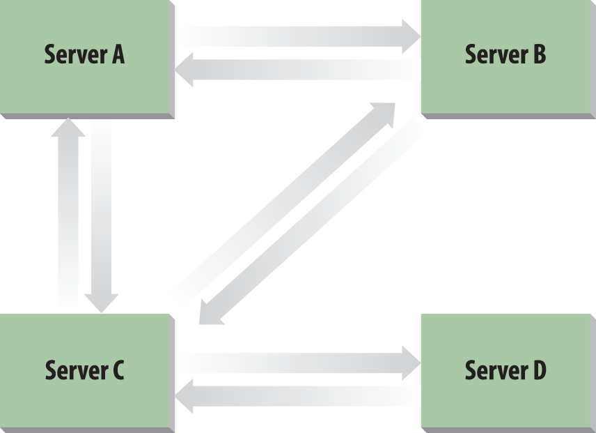
Server D comes along, and the promotion process starts. It picks Server C to connect to. Server D ends up creating the incoming connection object for Server C. Server C also creates the incoming connection object for Server D. You now have the loop from the previous section, plus a two-way connection from Server C to Server D. See Figure 14-1 for this topology.
Server D’s KCC now uses the newly replicated data from Server C to go through the existing topology. It knows that it has to continue the ring topology, and as it is already linked to Server C, Server D has to create an incoming connection object for one of Server C’s partners. It chooses Server B in this case. So, Server D’s KCC creates an incoming connection object for Server B. Server D then requests changes from Server B. The rest of the process can happen in a number of ways, so we’ll just play out one scenario.
Server B now knows about Server D. Server B’s KCC runs and realizes that it doesn’t need the link to Server C, so it deletes that connection and creates a new one directly to Server D itself. Finally, as replication takes place around the ring along the existing links, Server C notes that it has a now-defunct incoming link from Server B and removes it. You now have a simple ring, as depicted in Figure 14-2.

Eight servers
Once you hit eight servers connected together, you need more links across the ring if you are to maintain the three-hop rule. If you look at Figure 14-3, you will see this demonstrated. If the cross-ring links did not exist, some servers would be four hops away from one another. The KCC figures out which servers it wishes to link by allowing the last server to enter the ring to make the initial choice. Thus, if Server H is the newest server in the ring, it knows that Server D is four hops away and makes a connection to it. When Server D’s KCC receives the new data that Server H has linked to it, it reciprocates and creates a link to Server H.

However, this doesn’t completely solve the problem. Consider Server B and Server F: they’re still four hops away from each other. Now the KCC creates a link between these pairs to maintain the three-hop rule.
Now what?
We’ve now gone through the mechanism that the KCC uses for intrasite link generation between DCs. However, that’s not the whole story. Remember that Active Directory can have multiple domains per site, so what happens if we add contoso.com (a new domain in the same forest) to the same site, or even europe.cohovines.com (a new child domain)? The answer is the same for both, and it is based on NCs:
The Schema and Configuration NCs replicate across the enterprise, and they share a replication topology. Although they replicate separately, it is along the same links.
Each domain replicates only domain-wide, so the domain topologies for both domains stay in the same ring formation that they had previously.
Once the two domains integrate, the KCC-generated topologies for cohovines.com and the other domain stay the same. However, the KCC-generated Configuration/Schema replication topology that exists separately on both domains will form itself into its own ring, encompassing both domains according to standard KCC rules.
To summarize, when you have multiple domains in a site, each domain has its own KCC-generated topology connecting its DCs, but all the DCs in the site—no matter what domain they come from—connect in a separate topology representing Schema/Configuration replication.
Site Links: The Basic Building Blocks of Intersite Topologies
Having sites is all well and good, but you need to be able to connect them if you are ever going to replicate any data. An intersite connection of this type is known as a site link. Site links are created manually by the administrator and are used to indicate that it is possible for two or more sites to replicate with each other. Site links can connect more than two sites if the underlying physical network already connects multiple sites together; however, it is often easier to visualize and control replication connections if you limit yourself to two sites per site link.
Sites do not have to be physically connected by a network for replication to occur. Replication can occur via multiple links between any two hosts from separate sites. However, for Active Directory to be able to understand that replication should be occurring between these two sites, you have to create a site link between them.
We’ve mentioned that site links have a cost (see Chapter 6), but that’s not their only property. In fact, site links have four important properties:
- Name
An identifying name for the site link.
- Cost
An integer weighting for the site link that indicates the preference of the link relative to the other links that exist. Lower costs are more preferable; higher costs are less preferable.
- Schedule
The times that are available for replication to begin. Replication will not begin outside of the time windows specified in a schedule.
- Transports
The protocols that are used for replication along this link.
Cost
As each link has a cost, it is possible to calculate the total cost of traveling over any one route by adding up all the costs of the individual routes. If multiple routes exist between two sites, the KCC will automatically identify the lowest-cost route and use that for replication. If only a single route exists between any two sites, then the site link costs are irrelevant.
Schedule
The schedule on a link represents the time period when replication is allowed to be initiated across that link. Domain Controllers also maintain times that they are allowed to replicate. Obviously, if two DCs and a link do not have times that coincide, no replication will ever be possible.
Between the scheduled start and stop times for replication on a site link, the server is available to open so-called windows for replication to occur. As soon as any server that replicates through that link becomes available for replication, a replication window is opened between the site link and that server. As soon as two servers that need to replicate with each other have windows that coincide, replication can occur. Once a server becomes unavailable for replication, the window is removed for that server. Once the site link becomes unavailable, all windows close.
Warning
Schedules only define when replication can begin. Once replication has begun, it will not stop until it completes, regardless of the schedule defined on the site link.
Transport
Site links can currently replicate using two transport mechanisms:
Directory Service Remote Procedure Call (DS-RPC)
Inter-Site Messaging Simple Mail Transport Protocol (ISM-SMTP)
A site link using DS-RPC means that servers wishing to replicate using that site link can make direct synchronous connections using RPC across the link. As the transport protocol is synchronous, the replication across the connection is conducted and negotiated in real time between two partners. This is the normal sort of connection for a real-time link. In some scenarios, certain sites may have unpredictable availability or they may have a very unreliable or highly latent WAN connection. In these scenarios, SMTP replication can be appropriate.
The SMTP connector, as a site link using the ISM-SMTP transport is called, allows partner domain controllers to encrypt and email their updates to each other. In this scenario, Active Directory assumes that you already have an underlying SMTP-based connection mechanism between these two sites. If you don’t, you’ll have to set one up for this to work. If a connection is in place, the SMTP connector assumes that the existing underlying mail routing structure will sort out how mail is transferred. To that end, a site link using the SMTP connector ignores the scheduling tab, as it will send and receive updates automatically via the underlying system whenever the email system sends and receives them itself.
SMTP connector messages are encrypted using certificates, so to encrypt the messages you need to install special certificates on the domain controllers that will participate in SMTP replication. You can automatically request and install these certificates if you have an Enterprise Certification Authority (CA) running on Windows in your organization. Otherwise, reference Microsoft Knowledge Base article 321051 for instructions on requesting and installing certificates from a third-party CA.
Note
The SMTP replication protocol cannot be used for Domain NC replication. It can, however, be used to replicate Global Catalog, schema, and configuration information. This means that multisite domains with slow links will be required to use RPC for domain replication.
When the ISTG becomes involved
In order to generate the intersite replication topology, the ISTG actively uses site link costs to identify which routes it should be using for replication purposes. If a stable series of site links exists in an organization, and a new route is added with a lower cost, the ISTG will switch over to use the new link where appropriate and delete the old connection objects. The network of connections that the KCC creates is known as a minimum-cost spanning tree.
Site Link Bridges: The Second Building Blocks of Intersite Topologies
Site link bridges are only necessary in scenarios where you have disabled the “Bridge all site links” option in Active Directory. We discussed an example of when a site link bridge may be necessary in Chapter 6. To summarize, site link bridges are necessary when you wish to tell the KCC that it can create a direct replication connection between two domain controllers that are not directly connected according to the topology information in Active Directory.
Consider the sample topology in Figure 14-4, and assume for the purposes of this discussion that “Bridge all site links” is disabled in the sample topology and that the underlying network allows communication between Chicago and New York. Given this information, Chicago and New York cannot replicate directly with one another. Instead, Chicago must replicate with Denver, and New York must replicate with Denver as well. In the event that the Denver domain controller (DC02) goes down, there will be no replication between Chicago and New York. If you define a site link bridge that includes the Chicago-Denver and New York-Denver site links, however, Active Directory will be able to create a replication connection directly between Chicago and New York in the event that the Denver domain controller becomes unavailable.

Now that you’ve seen how site links and site link bridges work, let’s look at how to design your sites and their replication links.
14.2. Designing Sites and Links for Replication
There is only one really important point that is the overriding factor when designing a replication strategy for your network: how much traffic and over what period will you be replicating across the network? However, replication isn’t the only reason for creating sites. Sites also need to exist to group sets of machines together for ease of locating data, finding the nearest DC to authenticate with, finding the nearest DFS share mount point, locating System Center Configuration Manager distribution points, or routing email in an Exchange organization. This section looks at the steps involved in designing your sites and links for replication.
Step 1: Gather Background Data for Your Network
Before you sit down to design your site and WAN topology, you need to obtain the map of your existing network infrastructure. This map should contain all physical locations where your company has computers, along with every link between those locations. The speed and reliability of each link should be noted.
Additionally, you should write down all the subnets that correspond to the sites you have noted.
Step 2: Plan the Domain Controller Locations
Planning for placement of domain controllers is fairly easy, but determining the number of DCs to use is a different matter entirely.
Where to put domain controllers
Each workstation in a domain exists in a single site that it knows about. When a user tries to log onto the domain at a given workstation, the workstation authenticates to a DC from the local site, which it originally locates via a DNS query. If no DC is available in the local site, the workstation finds a remote site by way of the site topology and, by a process of negotiation with a DC in that site, either authenticates with that DC or is redirected to a better domain controller.
This consideration governs the placement of DCs. You should place one DC for authentication purposes per domain in all sites that meet any of the following criteria:
The site has links that are not fast enough for logon purposes to a particular domain.
The site has links that may be fast enough for logon, but you do not wish to authenticate across them for a particular domain.
An application that requires fast responses from a domain controller (such as Exchange) exists in the site.
You have overarching business requirements to ensure that authentication and directory information in that site will always be available, regardless of the WAN link status.
The first and second points also need to be considered in light of the number of users and workstations at the sites. If there are enough workstations at the site to generate logon traffic that will utilize a large percentage of the available WAN bandwidth, then you will probably be forced to place a local domain controller at the site.
How many domain controllers to have
Deciding how many DCs to place at a site is never easy. If you have a Windows server that’s already serving 500 heavy users and is close to its load limit, could it authenticate 100 additional users quickly enough at the same time? Powerful servers can authenticate hundreds or thousands of users simultaneously, but even these servers will balk if they are already heavily loaded.
There are some things that are tough to accurately assess, such as the impact of LDAP-based applications using the DCs. Often you do not know the specifics of how any given application uses the directory, so you end up taking a “wait and see” stance in terms of how many DCs will be needed and hoping that the usage levels aren’t so high that users will notice any performance problems.
Note
Exchange is an example of an application that ships with best practice guidelines for how many Global Catalog servers are required. Exchange defines these best practices in terms of a ratio of Exchange CPU cores to Global Catalog CPU cores.
The only way to definitively decide on how many domain controllers are required in a site is often to try the best practice and recommended guidelines, and then adjust the actual count to suit your reality as patterns become clear. That way, you should be able to judge for yourself how many DCs you may need for authentication and other purposes.
It is important that you define up front when planning your domain controller deployment what criteria you will use to justify an additional domain controller in a site. This usually depends on performance metrics such as average CPU utilization or disk utilization.
Placing a domain controller in more than one site
Any domain controller that you promote will belong to one site only. However, there can be instances in which you may want to configure a domain controller to cover multiple sites. For example, you might want to make sure that workstations from a number of sites all authenticate using one DC. Domain controllers perform a behavior by default called automatic site coverage, which registers the necessary DNS records for a domain controller to service multiple sites.
Automatic site coverage is important when you have sites without domain controllers, as clients in those sites will still need to authenticate and access Active Directory. In branch office scenarios, it is often ideal to modify this behavior so that domain controllers in branch offices don’t cover other sites. You can find more information on configuring this behavior in Chapter 4 of the Windows 2003 Branch Office Deployment Guide. It is no longer necessary to configure this behavior for Windows Server 2008 R2 and newer domain controllers.
Note
You can manually configure domain controllers to service
multiple sites by modifying a registry value. To do this, edit the
registry on the server that will be covering multiple sites and add
a REG_MULTI_SZ value called
SiteCoverage to the HKLMSYSTEMCurrentControlSetServicesNetlogonParameters
key. Add the names of the sites you want the server to cover to this
value.
Generally speaking, you should plan to rely on automatic site coverage; however, this manual functionality exists in case you need to make an exception.
Step 3: Design the Sites
From the network diagram, you need to draw your site structure and name each site, using a one-to-one mapping from the network diagram as your starting point. If you have 50 physical WAN locations, you have 50 sites. If only 30 of these will be used for Active Directory, you may not see a need to include the entire set of sites in Active Directory. If you do include the entire set, however, it is much easier to visualize your entire network and add clients or servers to those locations later.
Note
When drawing Active Directory topologies, sites often are represented by ovals.
Remember that a site is loosely defined as a well-connected set of subnets (“well-connected” tends to mean about 10 Mbps LAN speed). A site does not have to have a domain controller in it; it can be composed entirely of clients. If you have two buildings (or an entire campus) that is connected over 10/100 Mbps links, your entire location is a single site.
This is not a hard-and-fast rule. By the normal rules, two locations connected over a 2 Mbps link represent two distinct sites. You can, however, group networks together into single sites if you want to. You have to appreciate that there will be more replication than if you had created two sites and a site link, though, because DCs in both physical locations will maintain the intrasite replication ring topology. If you had created two sites and a site link, only the two bridgehead servers would replicate with each other.
To summarize, we would suggest that, by default, you create one site per physical location on your WAN, unless you do not feel a need to segregate replication between two physical locations.
Note
One counterexample to this general recommendation is in the case of high-speed links between datacenters. Some organizations deploy multiple physically separate datacenters that are effectively one logical location on the network. In this case, it may make sense to represent those datacenters as a single site.
Step 4: Create Site Links
Now that you have all the sites down on paper, you need to think about the links. In this step, we identify how sites are connected and to what degree we need to replicate the physical topology in Active Directory. Additionally, we identify any site links that will require nonstandard replication schedules and the frequencies at which site links replicate.
The first thing to consider is how you will name your site links. We recommend that you limit yourself to two sites per site link and adopt a naming convention that makes it easy to identify the sites involved in a site link. One strategy that works well is to place the two sites involved in both the name and description attributes, reversing the order. For example, you might make the name of the site link SiteA-SiteB and the description SiteB-SiteA. This makes it easy to sort on either field in Active Directory Sites and Services and see which site links involve a given site.
When applying costs to your site links, you should make every effort to use a standardized system for the cost values you choose across the entire deployment. There are multiple ways to implement this costing model, and there isn’t necessarily a “right” way to do it. Some organizations choose to assign link costs categorically, such that links between hub sites have a certain cost, links between hubs and spokes have another cost, and links between two spokes have a third cost. Other organizations choose to associate the site link costs with the speed of the underlying WAN connection. Remember that either way, if there is only one path to a site, the cost is irrelevant.
Note
For a discussion of using WAN speeds to populate site link cost values, see this website. This blog post also includes a spreadsheet that provides the costs of many common WAN link speeds.
The frequency is simply how often replication will occur over the site link. This value is specified in minutes and can range from 15 minutes to 1 week. You should choose this value based on the requirement for how up to date Active Directory data must be at either end of the site link, and also with respect to how much load replication will place on the underlying WAN link. If you do not have enough change volume to generate a significant amount of replication traffic, it will likely not be beneficial to you to make the frequency intervals very long.
The schedule is the final configurable option on site links. The site link schedule defines during what time windows replication is allowed to begin. “Begin” is an important word here, as once replication starts, it will not stop until it concludes, regardless of the site link schedule. Site link schedules are very helpful when working around WAN links that are saturated or unavailable during certain time periods.
Step 5: Create Site Link Bridges
If you elect to disable the “Bridge all site links” option, you will need to examine whether your topology requires site link bridges to help the ISTG generate your intersite topology. In many hub/spoke topologies, this step ends up being unnecessary, but you will need to examine yours to be sure.
14.3. Design Examples
Having considered the five steps, let’s take another look at the three examples from the previous chapter and see what they will need in terms of their site topologies.
Tailspin Toys
Tailspin Toys is an organization that employs approximately 3,000 people across North America. There are approximately 4,000 client computers and several hundred servers spread across the Tailspin Toys locations. Office workers are located in a number of cities across the United States and Canada, as well as in home offices. Manufacturing operations take place in Mexico.
Step 1: Gather background data for your network
The Tailspin Toys network is relatively modern, with fast and reliable connectivity to all of the offices in the United States and Canada. Some of the manufacturing plants have less reliable connectivity. All manufacturing sites are considered business critical and must be able to operate independently for a period of time in the event of a network outage.
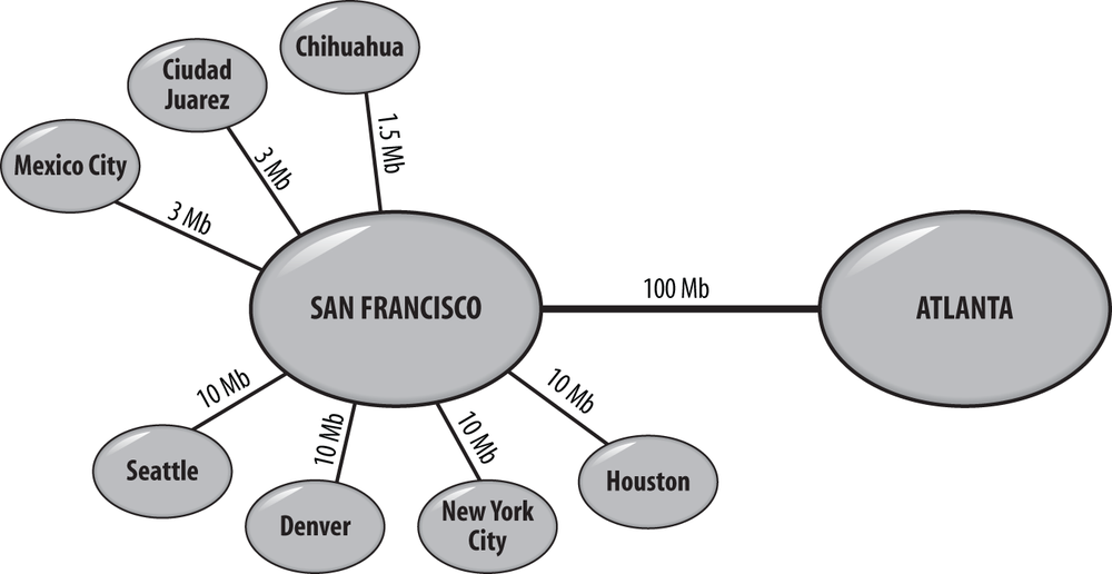
The organization’s primary datacenter is located in San Francisco. There is a disaster recovery site located in Atlanta. The network topology is shown in Figure 14-5.
Step 2: Plan the domain controller locations
Based on the network diagram in Figure 14-5 as well as historical network performance information, Tailspin Toys decides to locate writable domain controllers in its San Francisco and Atlanta datacenters to service clients in offices across the United States and applications hosted in the datacenters.
Given the critical nature of manufacturing operations, corporate policy, and WAN reliability, a read-only domain controller (RODC) is placed at each manufacturing site. The RODC is configured to cache passwords for all users, service accounts, and computers located at the site.
Step 3: Design the sites
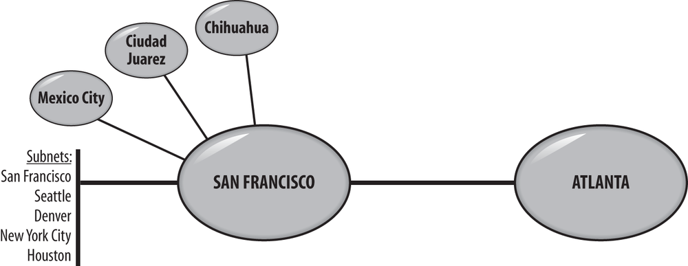
Tailspin Toys currently does not use any applications that are both site-aware and deployed into sites that do not have a domain controller. As a result, site objects and corresponding subnets are created for each location hosting domain controllers. The San Francisco site is also configured with the subnet objects for each of the branch offices in the United States.
Step 4: Create site links
Figure 14-6 shows the site link topology for the Tailspin Toys forest. Table 14-1 shows the site link configuration. A single site link is provisioned for each connection to San Francisco. Since there is only one path to each site, site link costs are not relevant. Standardized cost values are assigned to each site link. All links between datacenters are assigned a cost of 100. All links between datacenters and spoke sites are assigned a cost of 200.
Sites included | Name | Description | Cost | Frequency | Schedule |
San Francisco Atlanta | San Francisco-Atlanta | Atlanta-San Francisco | 100 | 15 minutes (change notification enabled) | Always |
San Francisco Mexico City | San Francisco-Mexico City | Mexico City-San Francisco | 200 | 180 minutes | Always |
San Francisco Ciudad Juárez | San Francisco- Ciudad Juárez | Ciudad Juárez -San Francisco | 200 | 180 minutes | Always |
San Francisco Chihuahua | San Francisco-Chihuahua | Chihuahua-San Francisco | 200 | 180 minutes | Always |
As you can see in Table 14-1, the high-speed link between the San Francisco and Atlanta datacenters also has change notification enabled. This ensures that domain controllers in both datacenters will always be virtually in sync. Since there is not a great need for data to be up to date on the RODCs in the manufacturing sites, replication is configured to occur every three hours (180 minutes) for those site links.
Contoso College
Contoso College is a higher education organization with approximately 3,500 employees, 30,000 students, and 5,000 computers. All users and computers are located at a single campus. There is a central datacenter managed by a central IT organization. In an effort to provide a centralized, sustainable, and distributed directory service, central IT is implementing an Active Directory forest that supports automatically managed user accounts and groups as well as the ability for delegated administrators to receive OUs whose resources they can manage as they wish.
Step 1: Gather background data for your network
The Contoso College campus is comprised of multiple buildings that are all connected to the central datacenter by high-speed fiber optic cables. The central datacenter is a physically secure facility with backup power.
Step 2: Plan the domain controller locations
Since the entire Contoso College campus is effectively a single well-connected local area network (LAN), writable domain controllers will be placed in the central datacenter. There will be no domain controllers located elsewhere on the network.
Step 3: Design the sites
Contoso College’s forest will be a single-site forest with all domain controllers located in the default site.
Step 4: Create site links
Since the forest will be a single site, there is no need to create any site links.
Fabrikam
Fabrikam is a global multibillion-dollar organization that has more than 250,000 employees and computers located at over 100 sites around the world. The business has its global headquarters in Chicago. There are four other major sites that link to the HQ and to which the smaller branch offices link: Asia-Pacific, North America, South America, and Europe. The small sites link to the hubs via links ranging from 64 kbps to T1 speeds; the hubs themselves connect to the HQ via a variety of higher-speed links. Some of the hubs are also interconnected.
Step 1: Gather background data for your network
Figure 14-7 shows the Fabrikam network topology at a high level. Links between datacenters are reliable although sometimes saturated. Multiple paths exist between the Europe, Asia-Pacific, and Chicago regional datacenters. WAN links to branch offices in South America and some offices in Asia are often slow, saturated, and unreliable. These sites often also contain business-critical functions such as manufacturing operations.

Fabrikam frequently opens and closes offices, and with over 100 offices, the subnet layout for the network changes frequently. To handle this, the Active Directory team receives a comma-separated values (CSV) file of subnets and their associated locations from the network team every night. An automated script processes the CSV file and ensures that Active Directory subnet information matches data from the network team.
Step 2: Plan the domain controller locations
Fabrikam plans to place writable domain controllers in each regional datacenter as well as the headquarters datacenter. The PDC emulator FSMO role holder will be placed in Chicago since Chicago is the most centrally located datacenter on the network.
Branch offices will receive a read-only domain controller if they meet any of the following criteria:
At least 100 computers are located at the site.
LDAP-integrated applications are hosted locally at the site and the WAN link is not reliable or fast enough to sustain the applications requirements.
Business-critical activities such as manufacturing operations take place at the site.
Step 3: Design the sites
Fabrikam has numerous Active Directory–aware applications deployed across the enterprise, as well as automated processes for managing subnet objects. Every physical location on the network will have a corresponding site object deployed even if there is no domain controller hosted locally.
Step 4: Create site links
The site link topology will mirror the WAN topology shown in Figure 14-7. Site links between datacenters will have change notification enabled. All other WAN links will replicate at varying frequencies, depending upon reliability and requirements.
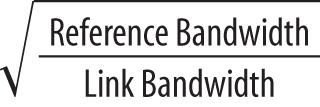
The cost attribute will be directly correlated to site link speed to account for multiple paths between some locations. Method C will be used to calculate the site link costs. Specifically, a reference bandwidth of 38400000000 bits per second (bps) will be used in the formula shown in Figure 14-8.
14.4. Additional Resources
Microsoft has produced an outstanding guide for customers setting up a branch office deployment. A branch office deployment is a deployment with a large number of WAN sites that need to host local copies of Active Directory. An example is a large retail chain that has a central office and hundreds of retail outlets that are all tied together into the same forest. If you have to deploy this kind of infrastructure, you absolutely need to review the Windows Server 2003 Active Directory Branch Office Guide; you can find it on the Microsoft website. Even though the guide was written for Windows Server 2003, it is still worth reading.
14.5. Summary
Based on this chapter, you should have a good understanding of how to go about designing the site topology for your Active Directory deployment and also how to determine if a domain controller is necessary in any given site. Site topologies are leveraged by Active Directory for replication and also by various other applications, such as DFS and Exchange Server. Clients also rely on the site topology to locate a domain controller for authentication.
The Knowledge Consistency Checker (KCC) is the process that runs automatically on each domain controller to generate the underlying replication connections. Intersite replication connections are generated on one domain controller in a site that is designated the Intersite Topology Generator (ISTG) for that site.
Planning your site topology requires a good understanding of the underlying network as you consider your requirements for sites, site links, and site link bridges. Sites represent disparate network locations where you want to segregate replication and authentication traffic. Site links represent the connectivity between sites, and site link bridges provide the KCC with hints about transitivity between site links for generating the necessary connections for replication to occur.
The next chapter deals with how to update your designs to reflect the requirements for group policy objects in your organization.