
Chapter 13. Designing the Active Directory Structure
The emphasis of this chapter is on planning the structure of your Active Directory installation. Specifically, we will look at the forest and domain tree layout as well as the organizational unit (OU) structure. While it was extremely common (and often necessary) to design a forest with numerous domains when Windows 2000 came about, that need has largely dissipated. We’ll explore how you can reduce the number of domains that you require for Active Directory while gaining administrative control over sections of the Active Directory domain namespace using organizational units. The purpose of this chapter is to help you create a domain namespace design. That includes all the domains you will need, the forest and domain-tree hierarchies, and the contents of those domains in terms of organizational units and even users, computers, and groups.
When designing a forest, remember that there are often multiple good answers to forest design for any given company. There is no “best” design for all situations. Microsoft has provided great flexibility in what can be done, which can turn around and bite you with indecision about how you should implement AD. It isn’t unusual for two engineers to have two very different designs for the same company that are both good for completely different reasons. Simply document all recommended designs and let the decision makers decide together which one will be the best for long-term operations. Overall, the best solutions are usually the simplest solutions. In most cases, you will want to choose single-forest designs over multiforest designs, single-tree designs over multitree designs, and single-domain designs over multidomain designs. The design example shown here is simply that: an example. The company in question could have designed its Active Directory infrastructure in a number of ways, and this is one of them.
There are a number of restrictions that you have to be aware of when beginning your Active Directory design. We will introduce you to them in context as we go along, but here are some important ones:
The forest, not the domain, is the security boundary for Active Directory. Anyone with high-level access rights on any writable domain controller in any domain can negatively impact or take control of any other DC or domain in the forest.
You can never remove the forest root domain without destroying the whole forest in the process. The forest root domain is the cornerstone of your forest.
Multiple domains cannot be hosted on a single DC. Imagine three child domains under a root domain located in the United States, each of which corresponds to one of three business units. Now imagine that you have a small office of 15 people in Eastern Europe or Latin America with a slow link to the US offices. These 15 users are made up of three sets of 5; each set of 5 users belongs to one of the three business units/domains. If you decide that the intersite link is too slow and you would like to install a local domain controller for these three domains at the remote site, you will need to install and support three separate domain controllers, one for each domain. While this could be virtualized, that is still three additional domain controllers to manage, update, and monitor.
Too many group policy objects (GPOs) often leads to long logon times, as the group policies are applied to sites, domains, and organizational units. This obviously has a bearing on your organizational unit structure, as a 10-deep organizational unit tree with GPOs applying at each branch will incur more GPO processing than a 5-deep organizational unit tree with GPOs at each branch. However, if the 10-deep and 5-deep OU structures both contained only two levels with GPOs, they would both incur the same GPO processing.
13.1. The Complexities of a Design
Active Directory is a complex service, and designing for it isn’t easy. Take a look at the fictitious global company called PetroCorp depicted in Figure 13-1.
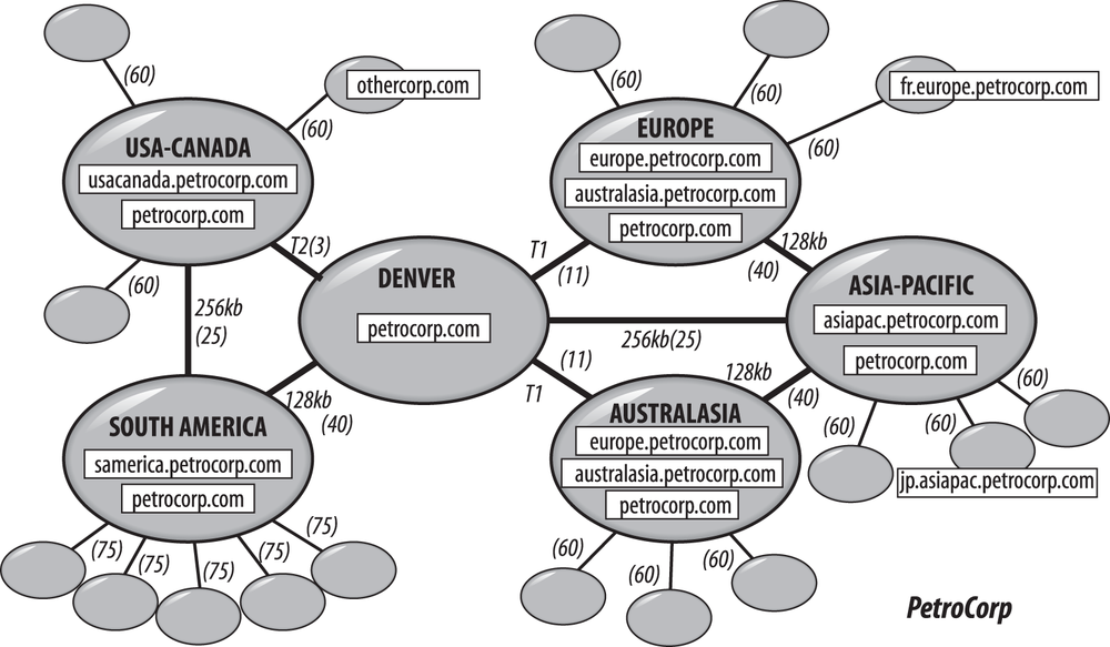
Here you can see a huge network of sites linked with various network connections across wide area networks (WANs). A variety of domains seem to exist for othercorp.com and petrocorp.com, and as each one of those square boxes represents a single domain controller, you can see that some of the servers will need to replicate data across those WAN links. For example, petrocorp.com seems to need to replicate to all the major sites, since it has domain controllers (DCs) in each of those sites.
Now take a look at Figure 13-2, which shows a much more complex hierarchy.

It’s possible to see the users and computers in all the organizational units in this view, and the structure seems to be set up so that group policy objects (represented by trapezoids) can be applied to various portions of the tree. The following is a discussion of the principles and processes that will help you create complicated designs like these to mirror the complexities in your own organization.
13.2. Where to Start
Before you sit down to make your design, you will need to obtain some important pieces of information. At a minimum, you will need:
A copy of your organizational structure, since this is effectively the document that explains how your organization’s business units fit together in the hierarchy.
A copy of the geographical layout of your company. This includes the large-scale picture in continents and countries and also the individual states, counties, or areas in which you have business units.
A copy of the network diagram(s), indicating the connection speeds between the various sites.
A copy of any diagrams and information on any systems that will need to interface to Active Directory, such as existing X.500 and LDAP directories and major applications, so that you can take them into account.
Once you’ve gathered the information, you can sit down and plan your design.
13.3. Overview of the Design Process
The namespace design process takes place in two stages:
- Design of the domain namespace
During the first stage, you deal with the namespace design itself. That means calculating the number of domains you need, designing the forest and tree structure, and defining the naming scheme for workstations, servers, and the network as a whole.
- Design of the internal domain structure
During the second stage, you need to concentrate on the internal structure of each domain that you have previously noted. Here you also need to use your business model as a template for the internal structure and then move on to consider how administration and other rights will be delegated. The internal structure can also be modified depending on how you intend to use group policy objects; this will be covered in Chapter 15.
Note
When you are finished with your design, you can implement it by setting up a test forest in a lab environment. This will enable you to get a better feel for how the design actually works and whether there is anything you have failed to consider. We can’t stress enough the importance of a test environment.
When working on the budget for your production forest, include time, money, and resources for the test environment as well. This up-front expenditure will undoubtedly save you considerable backend mistakes and uncertainty on a continual basis.
13.4. Domain Namespace Design
The first stage in your design is to work out the domain, domain tree, and forest configuration of your network. The best way to do this is to make a first pass at designing the domains and then structure them together into a single tree or a series of trees. Before we start, however, let’s take a look at our objectives for this part of the design.
Objectives
There are two objectives for the design of the domain namespace:
Designing Active Directory to represent the structure of your business
Minimizing the number of domains by making much more use of the more flexible organizational units
Represent the structure of your business
When designing your Active Directory environment, you should aim to make it both match the structure of your business, and also be managed by whatever management model your IT organization operates under. Typically, organizations fall into one of three or four common models for managing their IT infrastructure:
- Centralized administration
In this model, your entire IT infrastructure is centrally managed by one team.
- Decentralized administration
In this model, your IT infrastructure is typically managed either locally at each location or on an organizational basis, perhaps by department or division. It is difficult to deploy a common Active Directory forest in this model, as standards are often lax or nonexistent and Active Directory doesn’t lend itself particularly well to being administered by a large group from an infrastructure (e.g., domain controllers and forest-level configuration) perspective.
- Hybrid centralized/decentralized administration
In a large organization, this is likely to be the most common model. Certain components of Active Directory are managed centrally, such as the domain controllers and enterprise-wide configuration, while other components, such as objects stored in OUs, are managed by distributed IT staff.
- Outsourced administration
In this model, a third party manages your IT organization for you to some extent. The scope of outsourcing varies from organization to organization, but oftentimes architecture and engineering decisions are retained and not given to the outsourcer to handle.
When Active Directory first came to market in Windows 2000, it was common to deploy multiple domains to mimic the existing NT4 deployment or for various other reasons, and most large companies that deployed Active Directory early on still have this model today. There is nothing wrong with the early best practices, such as empty root domains or regional domains, but conventional wisdom today says that you should endeavor to have the fewest number of domains possible. That said, by no means are we recommending that you rush off to collapse domains created early on unless you can achieve cost or management savings that exceed the cost of this restructuring.
One of the most common justifications that will be made for an additional domain in the forest is a purely political requirement to separate administration. In reality, determined administrators of any domain in a forest could elevate their privileges to the Enterprise Admin level without too much work. Instead of creating a separate domain in this situation at a relatively high cost (with practically no benefit), use organizational units over which you can delegate the necessary permissions.
As you go through the process in this chapter, keep in mind that, especially in large organizations, businesses frequently reorganize. Develop a design that you feel can survive multiple reorganizations without substantial investment in changes to your Active Directory design. Our experience is that designs based more on geography, location, or support models tend to fare better as the organization evolves.
Step 1: Decide on the Number of Domains
Start by imagining that every object is to be stored in one domain. This will give you a much simpler layout for administration. It doesn’t matter what the domain is called for now; just label it as your organization’s main/sole domain.
Now expand the number of domains that you have by adding other domains that you can give specific justification for. While the number of objects and delegation of administration are not good reasons for creating new domains, there are still a couple reasons that would require more domains:
The need to isolate replication
A requirement for disparate Kerberos domain policies
If you can match either of these criteria, write down a new domain for that area.
Warning
There are good reasons to add domains to the design, but there are also good reasons to not add domains. You should weigh these against the requirements listed previously to determine which are most important.
Some reasons to not deploy an additional domain include:
- Forest complexity
Each domain requires more DCs, more policy management, and additional cost.
- Application complexity
Applications may only be able to search a single domain for information. Many Unix- and Java-based LDAP applications are generally written to have a single simple hierarchy and may not be able to be configured to work with a multidomain forest without serious work.
Isolated replication
Although we’ll discuss replication in more depth in the next chapter, you should begin to consider it from a high level at this point, as it can have a substantial impact on the domain design you settle upon. Many large organizations have elected to deploy domains in a regional fashion that matches major divisions in WAN topology. Such models often include domains such as Americas, AsiaPacific, and Europe or EMEA (EMEA is a common acronym for Europe, Middle East, and Africa). The reasoning for this is to segment replication at a high level. Environments with large domains cannot always bear the replication overhead of replicating all of the contents from an Americas domain to a remote site in Asia, for example.
Since Windows 2000, replication has improved greatly (with respect to compression, in particular), and WAN links have gotten faster in some regions. As you explore design options, you will need to consider whether or not your WAN could be impacted by the replication overhead of a large domain and if limiting this replication would be beneficial. Keep in mind that even if you segment your domains on a regional basis, there will still be some interregional replication for the Global Catalog.
Unique domain policy
In Chapter 11 and Chapter 15, we explain the basics of group policies and how to properly design them. For now, the important thing to understand is that policies are Active Directory objects that reference a number of settings that can be applied to users or computers. These settings are things like a fixed desktop, a certain core set of applications, the ability of users to perform a shutdown, and so on. If you create an organizational unit called Finance and then decide that it needs special settings, you can create a GPO and assign it to the OU. Then the computer settings and user settings in the GPO will be applied to all computers and users under the Finance OU.
We now need to look at what settings have to be applied on a domain-by-domain basis. Here’s a list of what types of settings can be set only on a domain-wide basis:
Kerberos policies
Encrypted filesystem (EFS) recovery policies
Public key encryption policies
If a special department or geographical area needs special encryption, security safeguards, certificates, and so on, you may need a separate domain for it.
Note
Domains that are not operating at the Windows Server 2008 or better functional level can only have one password policy per domain. For more information about fine-grained password policies, see Chapter 12.
Final notes
You now should have your first draft of the list of domains that you think you will need. There is one more very important point on this subject. Domains are very inflexible and unforgiving, and due to the fact that you can host only a single domain on a domain controller, each domain you add means at least one more domain controller you have to support.
Warning
For fault tolerance, you should always deploy new domains with at least two domain controllers. If you only have a single domain controller for a given domain and the domain controller fails, you will be forced to restore from a backup. This is easily avoided by deploying a second domain controller.
Depending on how many domain controllers you would have to deploy for a domain, you can greatly decrease your total cost of ownership (TCO) for Active Directory by limiting the number of domains you support. In general, we recommend that you start with a single-domain design for any new Active Directory forest unless you have a compelling technical reason not to.
Step 2: Design and Name the Tree Structure
Now that you have the domains listed, you need to consider what sort of hierarchy to put them in. It is easiest to start with one domain, the one that will become the forest root.
Choose the forest root domain
There are two ways to go about choosing the forest root domain. The first model is to deploy an empty root domain. The empty root simply contains a small number of domain controllers and accounts for the Active Directory administrators for the forest. The empty root is the most common model you’re likely to see in large environments that have had Active Directory deployed for some time.
Note
The security concerns that led many organizations to deploy an empty root have since been proven to be a nonissue. While the empty root model is perfectly valid, you should not choose to deploy a forest with an empty root solely with the goal of protecting the enterprise-wide groups (such as Enterprise Admins and Schema Admins).
The second model is to simply choose a domain that you know will be required for the lifetime of the forest as the forest root domain, which can never be removed. If you are deploying a single-domain forest, this decision is simple. If you are deploying multiple domains, you should keep in mind your namespace requirements as you design the hierarchy, such that the forest root domain is actually at the root of the tree.
If you are planning to deploy a single-domain forest—the model that we generally recommend—there is no reason to deploy an empty root simply because it is an option. Making your sole domain the forest root is perfectly acceptable.
Design the namespace naming scheme
As each domain has a DNS name to identify it, you need to consider what names you are going to choose. You can use any of the RFC 1123 standard characters:
A–Z
a–z
0–9
- (dash character)
Microsoft’s DNS server implementation supports a wider range of characters, such as the Unicode character set, but if you need compatibility with other DNS flavors, be very careful allowing these.
There are currently two schools of thought on how to pick the DNS names for your Active Directory network: root zone or subzone. The root zone method says that you name your root Active Directory domain based on the root zone for your organization. For the Coho Vines forest, this would be cohovines.com. The subzone method suggests that you pick a new subdomain from your root zone and make that the base of your Active Directory namespace. For Coho Vines, this could be ad.cohovines.com.
If you choose the root zone method and wish to have a non-Windows DNS server at your root, you will need to either enable dynamic updates or manually register a number of records in the DNS servers, as discussed in Chapter 8. If you choose the root zone method and wish to have a Windows DNS server at your root, you will need to migrate your existing entries, if you have any, to the new DNS servers. Both methods are fine, but they require configuration or migration at the root.
A less invasive procedure would be to choose a new subzone for your Active Directory network and run your network from that. With this setup, you still have two choices, but they are less disruptive to any existing structure and don’t affect the main root zone. Arguably, the easiest solution is to let two servers on your network run Windows DNS Server and manage this DNS zone. This allows you to have a root that doesn’t allow dynamic updates and a subdomain that does. In this case, your existing main root zone DNS servers would contain a DNS delegation for the subzone. The subzone would be delegated to your Active Directory DNS servers. The alternative would allow a non-Windows DNS server to manage the zone.
Another common extension of the root zone method is to choose a parallel namespace, such as cohovines.net, for your Active Directory network. This allows you to have a root-level namespace and not need to migrate existing DNS entries or manage a split-DNS model if cohovines.com is also your external namespace.
To continue with the planning process, start with the forest root: draw a triangle on the paper and assign a DNS name to the domain, writing the name inside or beside the triangle. You should choose the name very carefully, for two reasons. First, while renaming a domain is possible beginning with Windows Server 2003 Active Directory, it is a highly invasive process and is not generally recommended unless absolutely necessary. Second, you can never remove the forest root domain from Active Directory. If you need to change its name, you must destroy your entire forest and start again.
Create additional trees
Having created and named your forest root, you need to consider your other domains. If you have two distinct business units or companies, some analysts may think that they will require noncontiguous names to match the structure. This means that you will need two trees coming from a domain root. Think long and hard about this decision—multiple domain trees in a forest add complexity and often cause support and application confusion for no real benefit. Some common examples that people will use to indicate a perceived need for multiple trees are different email address suffixes, different UPN suffixes, resource separation, and security separation. However, separate trees aren’t actually required to implement any of these requirements.
If you still conclude that you need multiple trees, draw all the other tree root domains that you think you will need as separate triangles at the same horizontal level on the paper and assign them valid DNS names. These domains are all tree root domains, but they should not be confused with the forest root domain.
A real-world example of this scenario is the Microsoft brand name and the MSN brand name (Microsoft owns MSN). Both msn.com and microsoft.com could be separate trees in the same forest. They couldn’t be in the same tree without giving them a hierarchical link, i.e., msn.microsoft.com. However, the only real benefit for having an msn.com and a microsoft.com in the forest instead of an msn.microsoft.com is how it all looks on a PowerPoint presentation.
Note
If we think that Coho Vines’s Finance Department needs a separate domain, we will make a subdomain and call it finance.cohovines.com. Within Active Directory we could make finance.cohovines.com a separate tree in its own right, but since hierarchical and transitive trusts exist throughout a forest, we would gain absolutely nothing by doing this. The only differences come in choosing Finance to be a new domain (which we did) or a new forest in itself. Making it a new tree gains us absolutely nothing.
Create additional forests
So far, we’ve been considering domains that will exist in the same forest, but you may have business units that will require two entirely separate forests. How do you know if that is the case? There are a number of common scenarios for this.
If you have business units in an organization that are independent and in fact wish to be isolated from each other, then you must not combine them in a single forest. If you simply give each business unit its own domain, these business units can get the idea that they are autonomous and isolated from each other. However, in Active Directory, this level of isolation can be achieved only through separate forests. This is also the case if you need to comply with regulatory or legal isolation requirements.
The first and most common reason for this design may be political: certain business units may decide that they want to be as autonomous as possible. It may be that, politically, the Finance Department has to be completely separate, so you end up making a second forest with finance.cohovines.com as the second forest’s forest root domain. In effect, you are treating this business unit as a separate, autonomous, and noncontiguous part of the tree.
Another reason that you may need two forests involves having two businesses that must be separately maintained for regulatory or other legal reasons. Similarly, if you have a business that may be divested or sold in the future, it will be much easier to separate if this business exists in its own forest.
The third reason is one born out of necessity. Remember from Chapter 2 that certain aspects of a namespace are forest-wide in scope. If you want to isolate a separate schema or configuration partition, your only solution is to create a separate forest.
The fourth reason, which is becoming more common, is the need for a separate forest for Microsoft Exchange. Exchange is very tightly integrated into Active Directory and does not always allow for a clean separation of duties through delegation. Additionally, Exchange can have management challenges with multidomain deployments in a single forest. These two considerations can often result in a single-domain resource forest being implemented for Exchange, with trusts configured to the appropriate domains in the primary forest or to the primary forest itself.
Finally, a fifth reason is to separate specific users, servers, or applications. It is not uncommon to deploy a dedicated forest in a perimeter network and join those servers to a domain in the primary forest. A one-way trust from the primary domain(s)/forest to the perimeter network forest enables internal users to access applications in the perimeter network, but it does not allow servers in the perimeter network to access internal resources. A common extension of this model is a specific forest for external users (such as business partners or customers) that need to access an application.
If any of these reasons apply, you need to create a second forest root domain and give it a unique DNS name, as you did for the first forest root domain. In effect, you need to separate your designs and design each forest individually. The best thing to do now is to figure out how many forests you need and which domains from your list are going to be the forest root domains. Once you have determined this, you will name these root domains and then use a separate piece of paper to draw each forest. Maintain separate lists of domains for each forest. You’re now creating x designs, where x is the number of forests you have.
There is one other important point that you need to be aware of. While domains and trees in a forest maintain automatic trust relationships, it is possible to set up manual trust relationships with domains external to a forest. You can therefore set up manual trust relationships between forests. These relationships can be one-way trusts (A trusts B but B does not trust A) or two-way trusts (A trusts B and B trusts A).
Note
While there is transitive trust between all domains in a forest, it is not uncommon to create shortcut trusts in large multidomain forests. Shortcut trusts improve authentication performance in scenarios that require users in one child domain to access resources in another child domain. Without a shortcut trust, authentication traffic must walk the domain tree to get to the other child domain. Shortcut trusts create a direct path.
The first option allows other domains that are members of another domain tree in a different forest or that do not support Kerberos authentication to have limited access to a domain in the forest. Only resources in that domain will be visible; no other resources in the tree will be available for access. The second option is to create a forest trust between two forests. With a forest trust, all of the domains within each forest will transitively trust each other.
Arrange the subdomain hierarchy
You now have a forest root domain with a valid DNS name. You may have other domains that act as the roots of separate trees in the same forest; you may even have extra forest root domains representing separate forests entirely. Now you need to lay out the domain tree hierarchies. If you have a number of remaining domains listed on your sheet of paper from step 1, these are the subdomains that will form your domain-tree hierarchy.
Start with the first forest. Representing each domain with a triangle on the paper, arrange the domains in a hierarchical fashion beneath one of the domain tree roots in the forest. Name each domain appropriately, according to its position in the hierarchy. Repeat this process for all domains in this forest, then move on to the next forest (if necessary) and repeat.
For example, if we have cohovines.com as a tree root, and the North America, Europe, and Asia-Pacific regions all need separate domains, we can call them northamerica.cohovines.com, europe.cohovines.com, and asiapacific.cohovines.com. If the Asia-Pacific region needs a separate domain for Japan, we’ll arrange this domain beneath AsiaPacific, as japan.asiapacific.cohovines.com.
13.5. Design of the Internal Domain Structure
Having designed the domain namespace, you can now concentrate on the internals of each domain. The design process itself is the same for each domain, but the order is mostly up to you. The first domain that you should design is the forest root domain. After that, iterate through the tree, designing subdomains within that first tree. Once the tree is finished, go on to the next tree and start at the root as before.
When designing the internals of a domain, you need to consider both the hierarchical structure of organizational units and the users, groups, workstations, and servers that will reside within those organizational units. Let’s look at each of those in turn.
Note
Moving forward, when we refer to a hierarchy, a tree, or the directory tree, we mean the hierarchical organizational unit structure within a domain. We are not referring to the hierarchy of domain trees in a forest.
Step 3: Design the Hierarchy of Organizational Units
Earlier, when we discussed how to design domains, we spoke of how to minimize the number of domains you have. The idea is to represent your requirements for a hierarchical set of administrative permissions using organizational units instead.
OUs are the best way to structure your data because of their flexibility. They can be renamed and easily moved around within domains and placed at any point in the hierarchy without affecting their contents. These two facts make them very easy for administrators to manage.
There are four main reasons to structure your data in an effective hierarchy:
- To represent your business model to ease management
Partitioning your data into an OU structure that you will instantly recognize makes managing it much more comfortable than it would be with every user and computer in one OU.
- To delegate administration
Active Directory allows you to set up a hierarchical administration. If you have three branch locations, and the main administrator wants to make one branch completely autonomous with its own administrator but wants to continue to maintain control over the other two branches, it’s easy to set up. In a way, most of the limitations that you come up against when structuring Active Directory are limits that you set for yourself: political necessities, organizational models, and so on. Active Directory really won’t care how you structure your data.
- To apply policies to subsets of your users and computers
As group policies can be applied to each individual OU in the hierarchy, you can specify that different computers and users get different policies depending on where you place them in the tree.
For example, let’s say that you want to place interactive kiosk machines in the lobby of your office and allow people to interact with whatever applications you specify, such as company reports, maps of the building, and so on.
With Active Directory, if you apply group policies to a certain OU hierarchy, you can guarantee that any computer and user accounts that you create or move to that part of the tree will always implement the kiosk lockdown policies you have designed.
When creating organizational units, you need to ask:
How will the organizational units be used?
Who are the administrators and what sets of administrator permissions should they have?
What group policies will be applied?
The hierarchy should organize information in a manner that enables your administrative model, enables effective use of group policies, and allows you to delegate administration to various parts of the tree.
Warning
You should not nest user or computer accounts in an organizational unit structure in such a way that the group policies that apply to the accounts create a slowdown during the logon process. Microsoft recommends nesting no more than 10 organizational units deep, but in fact, to a much greater extent, it’s the application actions of group policies that you need to consider when designing your OU structure. This helps prevent slowdowns during boot (policies applied to the computer account on boot up) and logon (policies applied to the user account on logon).
Nesting OU structures excessively also has a tendency to lead to substantially increased administrative overhead due to the additional complexity of the model.
Recreating the business model
The easiest way to start a design is to consider the business and administrative models that you sat down with when creating these designs. You now need to recreate that structure in Active Directory using OUs as the building blocks. Create a complete OU structure that exactly mirrors your business model as represented by that domain. In other words, if the domain you are designing is the Finance domain, implement the finance organizational structure within that domain. You don’t create the entire organization’s business model within each organizational unit; you create only the part of the model that would actually apply to that OU. Draw this structure out on a piece of paper. Figure 13-3 shows a sample structure that matches the business’s organization directly. For simplicity, we’ve expanded only the Finance OU here.

Once you have drawn an OU structure as a template for your Active Directory hierarchy within the domain, you can begin to tailor it to your specific requirements. The easiest way to tailor the initial OU design is to consider the hierarchy that you wish to create for your delegation of administration.
Delegating full administration
First, identify any areas of your hierarchy where you need to grant administrators autonomous access over their branch of the tree. Each OU should have at least two administrators who will look after that organizational unit. These administrators will take care of the structure below the organizational unit, creating whatever OUs, users, groups, and so on that they desire. They will not, however, have administrative access to any other part of the tree.
You need to note two pieces of information about each of the organizational units that you identify:
Who will be the administrators?
Which branch of the tree will they administer?
Warning
You must ensure that delegated administrators take responsibility for their actions and can be held accountable. This cannot be stressed enough. It is entirely possible for an administrator of a low-level organizational unit to make changes that affect other people.
Delegating other rights
Having noted these two pieces of information for all organizational units that need full administrative access, you next need to identify those organizational units that require some users to have a more restricted set of permissions. You may want to set up account administrators that have the ability to create and delete user accounts, and to set passwords and account details. We’re interested in rights only in general terms at the moment, so just note the following:
What the access rights are
Which branch of the tree the access rights will be applied to
Which users or groups (in general terms) will have these access rights
It is possible to set access rights of any sort down to the individual property level on a specific object if you require. That means you can allow a user named George Washington to change the password or telephone number of a user named James Madison (and only that user) if you wish. Obviously, the more granular the access, the more complex things can get, especially since permissions are inherited down a tree by default. To make things easier, Microsoft provides a simple Delegation of Control Wizard that allows you to set these access rights in a fairly easy manner. Active Directory permissions are covered in much greater depth in Chapter 16; all we’re concerned with at this stage in the design is delegation of control at the organizational unit level. From experience, we can tell you that assigning access rights at the organizational unit level is always much simpler to manage than tracking permissions to individual objects and properties.
Note
Perhaps the most important thing to remember when designing your organizational unit structure is to make it consistent and repeatable. If you are creating an OU structure by location, develop a script to create that standard structure (and any applicable permissions delegations) for each of your locations. Managing OU structures that are independently designed and managed will quickly become extremely difficult, if not impossible, to do efficiently.
Step 4: Design the Workstation and Server Naming Conventions
You now have one or more forests of domain trees, as well as an OU structure. You can now consider the naming convention for the servers and workstations.
Note
While we are considering the naming convention here, the exact placement of machines in Active Directory is covered in Chapter 15, where we discuss designing GPOs. That is because GPOs can impact clients based on machine location.
Each client workstation or server in an Active Directory network must have a computer account somewhere in the forest to let users log on via that client. When a machine is added to a domain in a forest, the computer account is created in Active Directory, and a trust relationship is established between the client and the domain so that the client is recognized as a valid member of the domain.
Where a client is placed in the forest determines part of the name. Member servers are usually placed in the domain that hosts most of the users that use the server, and DCs are located by their very nature in the individual domains that they host. Clients can be placed anywhere, but they are usually placed in the domain that the primary users of that client will normally log onto.
All hosts are named <computer>.<domain>. For example, a server called SRV01 in the cohovines.com domain would usually be called srv01.cohovines.com; a server called SRV02 in the Europe domain would usually be called srv02.europe.cohovines.com.
Note
It isn’t normally discussed, but the DNS domain name of the machines in a given domain does not strictly need to match the Active Directory domain name.
This is one example of a disjoint namespace, and it is a supported configuration by Microsoft. This type of configuration is sometimes found in larger Enterprise-class organizations that have complex distributed DNS configurations. You may find, for example, a server with the name srv01.detroit.michigan.us.cohovines.com, which is a member of the AD domain northamerica.cohovines.com.
Deploying Active Directory does not force you to change the names of any existing hosts that you have. However, if you are planning to consolidate a number of separate domains, you need to ensure that all hostnames are unique within the domains they exist in, or throughout the entire company if WINS is being used with full mesh replication.
If you don’t already require a consistent naming scheme for your clients and servers, now is the time to create one. Fully qualified domain names must be unique across the entire forest; this is achieved by appending the domain component onto the computer name. That leaves you to worry about the prefix, meaning that computer names have to be unique only domain-wide.
To maintain backward compatibility, names cannot be longer than 15 characters. This is because Active Directory still has some legacy support for NetBIOS names, and the hostname that you choose will be incorporated as the NetBIOS name on the client. NetBIOS names are limited to 15 characters.
You need to work out a forest-wide naming convention, determining how you will name the clients and servers within the 15-character limit. The convention is up to you, but we supply some samples later in this chapter when we look at sample designs.
Step 5: Plan for Users and Groups
Before starting this section, we must make clear the distinction between groups and OUs. OUs are containers for objects that allow the objects to be represented in a hierarchical structure within a domain. Placing objects in such a hierarchy allows delegation of administration to those organizational units on a selective basis, as well as application of group policies. We’ve seen all this already.
Groups, on the other hand, have only users or computers (or other groups) as members and can be used in assigning permissions or rights to the members collectively. Let’s say that we have 50 users contained in an organizational unit called Finance, and the users are also members of a group called Finance Users. When we want to grant these 50 users read permissions to a share or restricted access to certain parts of a domain’s hierarchy, we assign the permissions to the Finance Users group. The fact that the users are in the Finance OU makes no difference when you wish to assign permissions to objects contained inside the OU. However, if we wish to delegate someone to have permission to manage those 50 accounts, we place the administrative delegation onto the OU. Here, we’ll be talking about how to effectively plan for user accounts and the groups to which those users belong.
Naming and placing users
When you are planning for user accounts, the only thing you
really have to worry about is the username or user identifier that the
client logs on with. Each username (the sAMAccountName property of a user object)
must be unique throughout each domain. If you have decided to delegate
administration within your organization, and you allow delegated
administrators to create user accounts, you need to create a naming
convention that each administrator will adhere to so that unique
usernames are generated for all users throughout your forest.
Warning
If you choose to allow delegated administrators the ability to create user accounts, consider the security implications carefully. When user accounts are created in a distributed fashion, there is generally no audit trail, well-established ownership chain, or account lifecycle applied to that user account. We strongly recommend that you look to centralize user creation through a request process or via an automated toolset to establish and maintain these types of security controls.
Another name that you assign to all Active Directory users is
the user principal name (the userPrincipalName attribute of the user
object). This property looks like an RFC 2822 email address, i.e.,
[email protected]. In reality, this property
is not the email address but is a unique identifier for the user
across the entire forest. The value must be unique as it uniquely
identifies a user across an entire forest. So, while having a user
with a sAMAccountName value of
George.Washington in cohovines.com and in executives.cohovines.com is perfectly
valid, the UPNs for each user account must be unique.
Often, UPNs are created by simply appending an @ symbol and the domain onto the end of the username. This ensures uniqueness because the username is unique in the domain, and appending the domain forces a unique forest-wide UPN. This makes [email protected] and [email protected] the UPNs for the two user accounts in the preceding example.
However, while it is conventional to construct the UPNs in this
way, you can in fact make the UPN of a user anything you wish as long
as it follows the format specified in RFC 2822. We could, for example,
append @cohovines.com to all our
users, eliminating the need to rely on domains at all. If we do this,
though, we should ensure that all of our usernames (sAMAccountName) are unique forest-wide. In
the previous example, we wouldn’t be able to have two users with the
username George.Washington. For such a scheme to
work, a central database or allocating authority needs to be set up to
uniquely generate and allocate names. If this database or authority
can generate unique usernames via a reliable algorithm, you can make
use of a much simpler UPN.
Note
Just because we chose @cohovines.com as the suffix does not mean we are limited to a forest or domain name. We could just as easily have chosen @contoso.com, which has no relation to the domains or the forest. The UPN simply has to be unique for every user in the forest.
Just as the suffix doesn’t have to match the forest or domain
name, the username portion doesn’t have to match the sAMAccountName. In fact, you can create a
user without specifying a sAMAccountName. This will autogenerate a
sAMAccountName that looks
something like $KJK000-H4GJL6AQOV1I, which really isn’t a
friendly logon name. However, you could then set the UPN to be
[email protected] and that could
be used to log on.
UPNs are very important. Imagine a user sitting down at a client
anywhere in a forest and being presented with the logon dialog box.
Here, the user can type in her username (sAMAccountName), password, and domain, and
be authenticated to the forest. However, it is perfectly valid to
authenticate with the UPN. If the user, presented with the same logon
dialog box, instead types a UPN in the username field, she will no
longer need to specify a domain.
In other words, a UPN and a password are all that is needed to authenticate to Active Directory. This makes sense since the UPN is unique forest-wide; apart from a password, nothing else should be needed. You now should be able to see that even with a very large and complex set of domains in a forest, you can use a simplified UPN form that does not contain a domain component and then simply instruct users to log on with a UPN and a password. This means that users never need to care about what domain they are in.
Many organizations choose to use their users’ email addresses as UPNs. The benefit to this strategy is twofold. The first benefit is that users can be instructed to log in with their email addresses and thus are required to remember one less piece of information. The second benefit is that email addresses are unique identifiers, so the UPNs will be too.
Your choice of where you place the user accounts in each domain’s hierarchy is really affected only by who is to administer the accounts and what GPOs will be applied on the OUs the accounts are in. Other than that, it makes little difference.
Naming and placing groups
Groups need unique names, too, so a naming scheme for groups should also be laid out in the design. Where you put groups is less important. In effect, groups can go almost anywhere in the hierarchy. The GPOs that determine your placement of users, for example, do not apply to groups.
Much like users, groups also have a sAMAccountName field that must be unique
within the domain. If you are delegating administration such that
delegated administrators can create groups, we recommend that you
devise a naming convention that establishes the department or
organization that owns the group in the name. For example, you might
prefix all group names with a two- or three-letter code that refers to
the group’s owner.
If possible, we highly recommend that you consider an external tool for managing group objects if you are going to delegate the ability to create and manage groups. This will allow you to establish group purpose, ownership, audit trails, and lifecycles for groups. This helps limit the sprawl of groups in the directory that have no known purpose or owner. Microsoft Forefront Identity Manager (FIM) is one example of a tool that can help meet this recommendation.
13.6. Other Design Considerations
In many cases, you may need to revise your designs a number of times. Certainly GPOs will make a difference as to how you structure your user and computer objects, so we do not expect that one pass through the design process will be enough.
Once you have a basic design, there is nothing stopping you from putting that design to one side and working on identifying a “perfect” design for your Active Directory network—one that you would like to implement in your organization, ignoring all Active Directory–imposed design constraints. You then can work out how difficult it would be to move to that perfect design from the practical one that you worked out using the preceding steps. You can look at the feasibility of moving from one to the other and then rationalize and adjust your final design to take into account the factors you have listed. You can then use this as an iteration tool so that your final design is much closer to the ideal.
Apart from GPOs, which we cover in Chapter 11 and Chapter 15, there are other aspects of Active Directory design that we have not and will not be covering. For example, you are quite likely to want printers advertised in Active Directory so that they can be accessed easily using a simple search of Active Directory. You might also want to use the Distributed Filesystem (DFS), which allows you to organize disjointed and distributed shares into a single contiguous hierarchy. When you reference a share held by the DFS, the DFS uses the Active Directory site topology to automatically redirect your request to the closest share replica. There is also the matter of designing your own objects and attributes that you want to include. If you’re thinking about this, there are two points that you should consider:
As a general rule, Active Directory should hold only static or relatively static data. At the very least, the lifetime of the data has to be greater than the time it takes to replicate to all DCs throughout the organization. When considering which objects to add, rule out objects with very short life spans. Dynamic data—that is, data with a relatively short life span—is more suited for storage in an application partition or an AD LDS instance, or possibly through the use of the dynamic objects feature.
Any object that you include will have attributes that are held in the Global Catalog. For every type of object that you seek to store in Active Directory, check the schema definition for that object to find out what attributes will be stored in the Global Catalog.
13.7. Design Examples
Having covered the design of the namespace and OU structure, some real-world example designs are in order. We have created a number of fictitious organizations that will serve as good models for demonstrations of the design process. The organizations themselves are not fully detailed here, although there is enough information to enable you to make a reasonable attempt at a design. In the chapters that follow, we will expand the relevant information on each company as required for different parts of the design.
We used a number of criteria to create these organizations:
The samples were set up to represent various organizations and structures.
While each organization has a sizeable number of users and machines, the design principles will scale down to smaller organizations well.
In these example organizations, we are not interested in how many domain controllers each company has or where those servers are. These facts come into play in the next chapter on the site topology. We are interested in users, groups, machines, domains, and the business and administration models that are used.
Tailspin Toys
Tailspin Toys is an organization that employs approximately 3,000 people across North America. There are approximately 4,000 client computers and several hundred servers spread across the Tailspin Toys locations. Office workers are located in a number of cities across the United States and Canada, as well as in home offices. Manufacturing operations take place in Mexico. The IT Department located in the San Francisco headquarters office manages IT assets across the entire organization.
Step 1: Decide on the number of domains
Given the small size of the organization, and connectivity requirements, Tailspin Toys elects to deploy a single-domain Active Directory forest. There are no requirements identified where a separation of replication would be necessary. Likewise, there are no concerns that require any resources to be separated into a separate forest.
Step 2: Design and name the tree structure
This domain/forest will be called tailspintoys.com with a NetBIOS name of Tailspin. Given the simple design, there is no need to worry about tree structures or naming beyond the name of the root domain.
Step 3: Design the hierarchy of organizational units
Tailspin Toys manages almost all of the objects in Active Directory centrally. Since there is limited need for complex permissions delegations, Tailspin Toys focused on Group Policy when designing its OU structure. After reviewing the organization’s needs, a location- and object-based OU structure was developed. This allows policies to be targeted to physical locations as well as specific types of objects (e.g., desktop computers versus laptops). Figure 13-4 shows the top-level OU structure for Tailspin Toys.

Due to the business-critical nature of machines that support manufacturing activities, a separate Manufacturing OU structure was established for shop-floor computers to isolate them from management of end user machines.
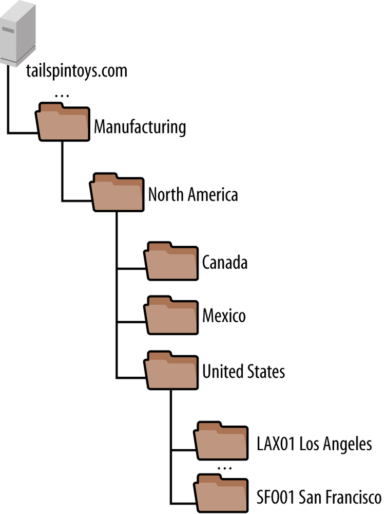
Figure 13-5 shows the OU structure under the Locations OU for the San Francisco office, as well as the parent structure. Organizing the machines hierarchically by geography allows the IT Department to apply group policies targeting users globally, regionally, or at a per-location level. The IT Department has also assigned a location code to each site to identify the site on the network. For simplicity, location codes are a combination of the three-letter airport code for the city as well as a two-digit number, in case there are multiple offices in a given city.

To keep management straightforward, a similar structure was developed for the Manufacturing OU. Since the Manufacturing OU will only contain machines used to support shop-floor activities, a consolidated version of the structure in Figure 13-5 was developed, as shown in Figure 13-6. Manufacturing machines are simply placed in the site’s OU.
Once the OU structure was finalized, a permissions delegation plan was developed. Based on Tailspin Toys’s centralized IT organizational model, there are only two sets of permissions that need to be delegated in Active Directory:
Password reset and account unlock for helpdesk analysts
Join computers to the domain for desktop technicians
Both of these tasks were easily delegated using the Delegation of Control Wizard in Active Directory Users and Computers.
Step 4: Design the workstation and server naming conventions
Since Tailspin Toys places its workstations in OUs based on the physical location of the machine, the type of machine (e.g., desktop or laptop), and the function (client computer, kiosk, or manufacturing machine), it decided to incorporate all of these data points in its naming convention. Additionally, based on input from desktop technicians in the field, the location (e.g., office number or cubicle) of the machine at an individual site is incorporated as well.
Tailspin’s naming convention is documented in Figure 13-7. The naming convention documents each possible character within the 15-character maximum limitation Active Directory imposes.
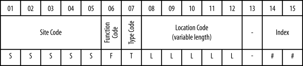
The fields are:
- Site Code
This is the five-character code assigned to each physical location. Tailspin uses these codes across all of IT, including network devices, servers, desktops, and the OU structure in Figure 13-5. The first three letters are the airport code for the nearest major airport, followed by a two-digit number identifying the specific location within a given city.
- Function Code
This letter identifies whether the machine is a client computer (C), a kiosk machine (K), or a manufacturing machine (M).
- Type Code
This letter identifies whether the machine is a PC desktop (D), PC laptop (L), Macintosh desktop (M), or Macintosh laptop (P).
- Location Code
This field allows for up to five characters that can be assigned by the local desktop technician. Desktop technicians typically encode the office location, cubicle, shop floor column number, or similar information in this field.
- Index
This is a numeric field, beginning with 01, used to disambiguate multiple machines in a given location.
Based on the correlation of the naming convention to the OU structure, a script is developed to automatically move any machines in the default Computers container to the appropriate OU. The script is scheduled to run every five minutes. This alleviates the need for IT to manually move computers in the directory.
The server naming convention illustrated in Figure 13-8 is straightforward and similar to the desktop naming convention.
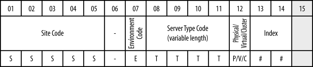
The fields are as follows:
- Site Code
This is the five-character code assigned to each physical location. Tailspin uses these codes across all of IT, including network devices, servers, desktops, and the OU structure in Figure 13-5. The first three letters are the airport code for the nearest major airport, followed by a two-digit number identifying the specific location within a given city.
- Environment Code
This letter identifies whether the server is in a production (P), test (T), or development (D) environment.
- Server Type Code
This three- to four-character field generically identifies the server type. A list of server type codes used by Tailspin Toys is documented in Table 13-1.
Warning
We have successfully used naming conventions very similar to the one documented here on numerous occasions. Do not define a server type code for every single permutation of server you can imagine. If you don’t have a need to differentiate different types of servers on the network by name, then stick with a generic type code.
We often use the application server type code when there is not a specific type code defined for a new server that is being introduced.
- Physical/Virtual/Cluster Indicator
This letter identifies whether the server is running on physical hardware (P) or in a virtualized environment (V), or if the name represents a cluster virtual name (C).
- Index
This is a numeric field, beginning with 01, used to disambiguate multiple servers in a given site of the same type.
Step 5: Plan for users and groups
Given the relatively small size of Tailspin Toys, a simple user naming convention comprised of the first initial of the user’s first name followed by the user’s last name is devised. For example, George Washington’s username would be gwashington. In the event of a conflict, a two-digit sequential number is appended to the end of the username to guarantee its uniqueness.
Since all groups will be centrally managed by the IT Department,
names are assigned on an ad hoc basis that best corresponds to the
purpose of the group. A policy is in place that requires the purpose
of the group as well as two functional owners for the group to be
listed in the notes attribute of
each group. The group’s functional owners are responsible for
approving additions of users to groups as well as reporting on what
the group is used for.
Contoso College
Contoso College is a higher education organization with approximately 3,500 employees, 30,000 students, and 5,000 computers. All users and computers are located at a single campus. Administration of IT resources is decentralized, with individual departments maintaining large-scale autonomy over the computers and resources in their areas. In an effort to provide a centralized, sustainable, and distributed directory service, central IT is implementing an Active Directory forest that supports automatically managed user accounts and groups as well as the ability for delegated administrators to receive OUs whose resources they can manage as they wish.
Step 1: Decide on the number of domains
Given Contoso’s plans to include students in the central Active Directory forest, there is a great deal of debate surrounding whether or not student accounts should be placed in a separate child domain or even in a separate forest. A separate student account forest is quickly ruled out, given the need for a central directory for applications to interact with, as well as the need for straightforward management. After reviewing the facts, including the reality that child domains do not create security boundaries, Contoso College decides to move forward with a single-domain forest that will contain all of the user accounts.
Step 2: Design and name the tree structure
Contoso already has an existing DNS infrastructure running on Unix BIND servers. Since the Windows administration team will manage Active Directory, and the Unix BIND environment is not configured to support dynamic updates, Active Directory will be deployed in a subzone of Contoso’s root domain (contoso-college.edu). The subzone will be delegated to the Active Directory domain controllers and hosted in an Active Directory–integrated DNS zone. In order to provide a generic name for the domain, the DNS name of net.contoso-college.edu is chosen. The NetBIOS name of NET will be used.
Step 3: Design the hierarchy of organizational units
Contoso needs to satisfy a number of sometimes competing demands while planning the OU structure. The first is for a domain that is manageable by central IT resources while also being flexible enough to meet the needs of delegated administrators in various departments at the college. In order to meet these needs, Contoso develops the top-level OU structure shown in Figure 13-9.

Here is a description of each top-level OU in Figure 13-9:
- Shared Resources
This OU contains objects that relate to the support of the forest and the network as a whole. These resources include administrative accounts, centrally managed groups, and centrally managed servers (excluding domain controllers).
- People
Since user objects will be managed by an automated identity management solution, it makes the most sense for those objects to be in a centrally managed OU. Contoso decides not to split user accounts by user type (e.g., employee or student) or location, since many users at the college have multiple roles and sometimes multiple jobs. It is not uncommon for an employee to be taking a class and thus be considered a student as well, for example.
- Delegated OUs
Under this OU, each OU that is requested by a department administrator will be created. OUs are nested under the Delegated OUs OU in case there is a need to apply a group policy or security delegation to all of the objects without affecting shared resources, domain controllers, and so forth. We will look at this structure in more depth later in this section.
The structure for each delegated OU is a blend of a fixed structure that is common across the environment with the flexibility for delegated administrators to create OUs in certain locations. Figure 13-10 shows the fixed structure that is created under each delegated OU.

Within each delegated OU, there are a number of child OUs:
- Groups
Any group object that delegated administrators create is placed in this OU. Additionally, a number of groups that are created with the OU structure and delegated permissions are placed in this OU. Delegated administrators can then manage rights to their OU structures by simply nesting users in the correct groups.
For the Groups OU, a group called <Department Name> - Group Managers is created and delegated the ability to create, delete, and manage all of the groups in the department’s Groups OU.
- Users
User accounts that correspond to students and employees are placed in the top-level People OU shown in Figure 13-9. Delegated administrators may create accounts for guests that need temporary access as well as service accounts for applications running on servers managed by the OU owner. Contoso’s security policy states that the OU owner is responsible for managing the lifecycle of these accounts and is responsible for any actions taken on the network by these users.
Two groups are created with permissions delegated over the OUs under the Users OU. A <Department Name> - Guest Managers group has the ability to create, delete, and manage user objects in the Guests OU. Likewise, the <Department Name> - Service Account Managers group has the ability to create, delete, and manage user accounts in the Service Accounts OU.
- Computers
The Computers OU has a number of child OUs. It is intended to hold all of the client computers managed by the OU owner. A group called <Department Name> - Allow Domain Join is created that is granted rights to join computers to the domain. This group also has rights on the default Computers container in the domain to reset computer account passwords and change computer account names.
The Desktops, Laptops, and Kiosks OUs are governed by a group called <Department Name> - Computer Managers. This group has the ability to manage computer objects in these OUs as well as move computers between OUs. Members of the group can also create child OUs under the Desktops, Laptops, and Kiosks OUs.
The Labs OU is specially designated for computer labs that typically contain student use computers. Computer labs often require special Group Policy configurations, so they are separated to ensure those policies are not applied to normal client computers. A group called <Department Name> - Lab Computer Managers has rights to manage computer objects under the Labs hierarchy as well as create child OUs.
- Servers
The Servers OU contains servers managed by the department. Contoso’s security policy states that OU owners are responsible for the security of any servers that are managed by the department.
Step 4: Design the workstation and server naming conventions
Due to the distributed nature of Contoso College, there is no well-defined workstation or server naming convention in use across the organization. Departments are required to register a prefix of two to five characters with the central IT organization when they receive a delegated OU. All workstation and server names must be prefixed with this code. Computer accounts are automatically moved to the correct OU based on the prefix on the computer object’s name.
Step 5: Plan for users and groups
Contoso College assigns a unique username to every user when they are entered into the college-wide enterprise resource planning (ERP) system. This username is reflected in Active Directory by the identity management system when the user’s account is provisioned. If a user wants to change her username, she must request this change via the Human Resources or Student Affairs Department. If the change is approved, it will be entered into the ERP system and then automatically reflected in Active Directory.
In the case of manually created accounts such as guests, Contoso’s security policy states that guest account usernames must be prefixed with g-. Additionally, these accounts must have an expiration date defined in Active Directory. Central IT automatically disables guest accounts that do not have an expiration date defined on a nightly basis.
Service accounts must be prefixed with sa- and the description field must explain the purpose of the account.
Groups may be named however the creator desires; however, the name must be prefixed with the two- to five-character code that is registered with IT when an OU is requested. This ensures that group names will not conflict.
Fabrikam
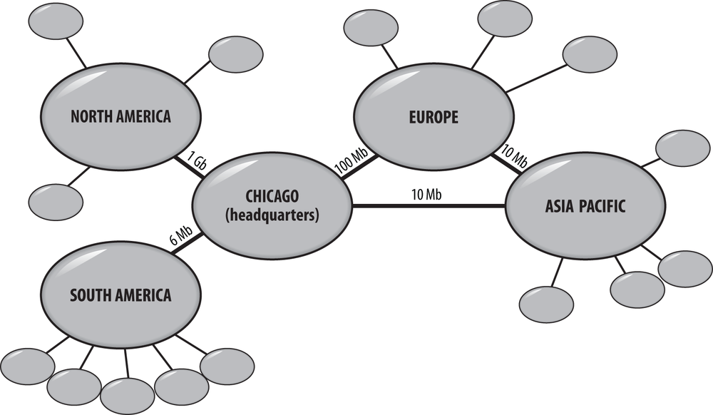
Fabrikam is a global multibillion-dollar organization that has more than 250,000 employees and computers located at over 100 sites around the world. The business has its global headquarters in Chicago. There are four other major sites that link to the HQ and to which the smaller branch offices link: Asia-Pacific, North America, South America, and Europe. The small sites link to the hubs via links ranging from 64 kbps to T1 speeds; the hubs themselves connect to the HQ via a variety of higher-speed links. Some of the hubs are also interconnected.
Fabrikam’s management structure is regionalized, with each geographical unit running itself as an independent business as part of the global organization. The top level of the management structure is located at headquarters, which sits above the four hubs. Even though Chicago could be considered within the North America region, the organization is not structured that way. In fact, IT personnel in Chicago oversee the hubs in terms of selecting the administrators and determinig how the network is to be structured. Corporate IT policy dictates that branches that have more than 500 people have their own local administrator, backup support, and helpdesk staff. Branches with fewer than 500 people have to be managed by the administrators of the hub to which they connect (see Figure 13-11).
Other considerations include the following:
Fabrikam recently acquired Trey Research, a Canadian company that has a strong brand name that Fabrikam would like to maintain. Trey Research is solely based in a new branch in Canada.
The links between the South American branch offices and the hub are very unreliable.
The Asia-Pacific hub site link to Europe is often severely congested.
Step 1: Decide on number of domains
Traditionally, if Fabrikam were designing its Active Directory installation in the Windows 2000 time frame, it would likely have opted to deploy an empty root domain with a series of child domains organized by region (e.g., domains for North America, Europe, South America, and the Asia-Pacific region). Considering the size of the directory and the network connectivity challenges that Fabrikam faces in South America and Asia, it is not out of the question that segregating replication by deploying child domains in some regions may be an appropriate and necessary solution.
Considering the relative cost and complexity of deploying a multidomain forest, as well as the lack of complete performance data and impact analysis around the network, Fabrikam decides to move forward with a single-domain forest. When considering the impact of replication, Fabrikam recognized that the benefits of a multidomain forest would be somewhat limited in the branch offices with domain controllers, as they would still require local Global Catalog presences. In the event that it becomes apparent that performance in South America or Asia is adversely impacted by using a single global domain, Fabrikam will deploy a child domain in that region and migrate users, computers, and other resources into the child domain.
Trey Research is an independent subsidiary of Fabrikam that Fabrikam intends to maintain as a separate company. Trey Research has contracts with Fabrikam competitors, and management feels there is a potential that Trey Research may be divested in the future. As a result, Trey Research will continue to maintain a separate forest with a two-way trust to the Fabrikam forest.
Step 2: Design and name the tree structure
Fabrikam has an existing DNS infrastructure, and the cost of moving to a split-brain DNS model for the fabrikam.com zone is prohibitive. Currently, Fabrikam owns the fabrikam.net domain name, but the namespace is not being used for anything. Consequently, Fabrikam decides to deploy its forest root domain as fabrikam.net with a NetBIOS name of FABRIKAM.
Once the forest is operational, a two-way forest trust is established with the treyresearch.com domain.
Step 3: Design the hierarchy of organizational units
Given Fabrikam’s semi-decentralized model of IT administration, a good number of permissions will need to be delegated to technicians at branch offices that manage IT resources locally. All of the IT personnel across the company are ultimately accountable to the headquarters IT staff in Chicago, so control will not be delegated such that local personnel have carte blanche access to their respective locations.
Instead, a standardized structure will be put in place for each location. Local personnel will have access to perform tasks relevant to their jobs, and IT personnel at the headquarters office will have access across all locations in the company.
Figure 13-12 shows the top-level structure for the Fabrikam domain.

Here is a description of each top-level OU:
- Enterprise Support
This OU contains objects that relate to the support of the forest and the network as a whole. These resources primarily include administrative accounts and service accounts.
- Sites
This OU is the parent for OUs that represent each Fabrikam office. We’ll look at the structure for this OU shortly.
- Groups
Fabrikam elects to manage all groups through a central, web-based group management tool. Consequently, groups are all placed in a single OU that has no delegated access.
- Servers
Fabrikam’s IT security policy states that all servers of a specific function must have the same policy and settings applied to them. Servers are organized into child OUs by the type of service or application running on the server so that a group policy can be applied to all servers of that type.
The Sites OU is shown in Figure 13-13. Each location-specific OU is organized by region, country, and then site. This allows administrators to delegate control at each level of the hierarchy (for example, to grant helpdesk analysts in Singapore the ability to reset user passwords for all users in Asia), as well as to apply group policies at any level of the hierarchy.
Note
Before you start building all of this in a GUI like Active Directory Users and Computers, pull the Active Directory Cookbook by Laura E. Hunter and Robbie Allen (O’Reilly) off the bookshelf and put together a script to build the OU structures and permissions. Since the structures will all be identical, the best mechanism to maintain consistency over time is to script the process. Administrators don’t want to be data-entry clerks, so building a structure like this is a perfect task for a script.

Step 4: Design the workstation and server naming conventions
Fabrikam is using a desktop management solution to keep track of all its desktops and laptops. Machines also move around the company fairly frequently, and employees often do not stay employed with the organization for long periods of time. Consequently, Fabrikam doesn’t want to encode information about the location of the computer or the employee using the machine in the name. At the same time, Fabrikam needs to ensure computer names are unique on the network and have a way of correlating a given machine to its record in the desktop management database.
To achieve this, Fabrikam decides to name each machine based on its manufacturer’s serial number. Since Fabrikam uses multiple suppliers for desktops and laptops, it decides to prefix the machine’s serial number with a two-character code for the machine’s manufacturer, as shown in Table 13-2. This naming convention is easy for technicians to implement, never requires a change in the machine’s name, and guarantees correlation of the machine name with the asset management database.
Code | Manufacturer |
AP | Apple |
DL | Dell |
HP | Hewlett-Packard (HP) |
IB | IBM |
LN | Lenovo |
For servers, Fabrikam maintains information about each server and what its role is in a configuration management database (CMDB). Since all of this information is tracked in the CMDB, Fabrikam decides to name servers based on a location code for the site hosting the server followed by a sequential four-digit number that uniquely identifies the server at that location. For example, a server at the SEA01 site might be named SEA01-0096.
Step 5: Plan for users and groups
User accounts will be provisioned automatically from the central human resources (HR) database maintained at the Chicago headquarters. Due to the sheer number of employees and the potential for duplicates, the provisioning system constructs a unique username for each user that is comprised of portions of the user’s first name, middle initial, and last name.
Groups are named arbitrarily by the user that creates the group through the central group management system.
13.8. Recognizing Nirvana’s Problems
Arguably, there are a number of “best” ways to design, depending on whom you talk to. We propose an iterative approach with Active Directory, and this is probably going to happen anyway due to the nature of the many competing factors that come into play. On your first pass through this chapter, you’ll get a draft design in hand for the namespace. In Chapter 14, you’ll get a draft site and replication design. Then you’ll come up against the issue that your namespace design may need changing based on the new draft site and replication design, specifically with regard to the issues of domain replication and server placement that we have just covered. After you’ve revised the namespace design, you can sit down and look at the GPO design (referring to Chapter 11 and Chapter 15) in a broad sense, as this will have an impact on the OU structure that you have previously drafted in your namespace design.
While this is the way to design, you will come up against parts of your organization that do not fit in with the design that you’re making. The point is to realize that your job is to identify a very good solution for your organization and then decide how to adapt that solution to the real world that your company inhabits. One domain may be ideal but may not be practicable in terms of cost or human resources. You have to go through stages of modifying the design to arrive at a compromise solution that you’re happy with.
Finally, we want to stress that the case studies in this book are only examples! There are multiple ways each of these cases could have been designed. We chose designs that we felt would work given the limited information available about each sample organization as well as the amount of space available to us in this book.
Do not assume that the designs you saw in this section are indications of how you should design your directory. We think they are excellent starting points, but you need to take your requirements and develop a design that fits best for your organization.
13.9. Summary
In this chapter, we presented five steps toward effective namespace design:
Decide on the number of domains.
Design and name the tree structure.
Design the hierarchy of organizational units.
Design the workstation and server naming conventions.
Plan for users and groups.
Following these steps allows you to solve the two main objectives of this chapter:
Come up with an Active Directory namespace design to represent the structure of your business.
Minimize the number of domains by making much more use of the more flexible organizational units.
Although we’ve shown you how to start to design your Active Directory installation, there is still a long way to go. Designing the namespace of domains, trees, and forests and the internal OU structure according to the guidelines given here means that you should have a baseline structural template that represents your business model and requirements within the preceding restrictions. Hopefully this design makes sense in terms of your organization and will be straightforward to manage.
The rest of the design still needs to be completed, though. You need to look at the low-level network links between sites and how they will affect your replication decisions. You then need to tackle the subject of how to revise the initial namespace design based on group policy objects, security delegation and auditing, schema changes, and so on. Next, we’ll move on to designing the physical site topology that the DCs use when communicating with one another.