10
Network Management and Orchestration
Luis M. Contreras1, Víctor López1, Ricard Vilalta2, Ramon Casellas2, Raúl Muñoz2, Wei Jiang3, Hans Schotten3, Jose Alcaraz‐Calero4, Qi Wang4, Balázs Sonkoly5 and László Toka5
1 Telefónica Global CTO Unit, Spain
2 Centre Tecnològic de Telecomunicacions de Catalunya (CTTC), Spain
3 German Research Center for Artificial Intelligence (DFKI), Germany
4 University of the West of Scotland, United Kingdom
5 Budapest University of Technology and Economics, Hungary
10.1 Introduction
This chapter provides an insight into network management and orchestration in the 5th generation (5G), in particular highlighting how software‐defined networking (SDN) and network function virtualization (NFV) will enable increased agility, scalability, and faster time‐to‐market of 5G communication networks.
SDN proposes the decoupling of both the control plane (CP) and user plane (UP), which are commonly integrated nowadays in the network elements (NEs), by logically centralizing the control while leaving the NEs to forward traffic and apply policies according to instructions received from the control side. This permits the network to become programmable in a way that facilitates more flexibility than traditional networks. On the other hand, NFV enables the dynamic instantiation of network functions (NFs) on top of commodity hardware, permitting the separation of the current vertical approach. This vertical approach consists of deploying integrated functional software and hardware for a given NF. Although they have emerged as separate innovative initiatives in the industry, both SDN and NFV are complementary, with the prevalent view in the industry that ‘SDN enables NFV’.
Traditional telecommunications networks have been built relying on a diversity of monolithic hardware devices designed and manufactured by distinct vendors. This approach requires complex and static planning and provisioning from the perspective of the service and the network. This static and complex approach on how the network services have been conceived and deployed over the last decades has triggered a continuous process of re‐architecting the network, tailoring topologies and capacity for the design and introduction of any new service in the network.
Current telecom networks require a rapid adaptation to forthcoming 5G services and demands, and if there is not an evolution of the conventional management and operation frameworks, it would create difficulties to deploy the services fast enough. The carrier networks are usually multi‐technology, multi‐vendor and multi‐layer, which translates into complex procedures for service delivery due to the different adaptations needed for the multiplicity of dimensions. In addition to that, the carrier networks are structured across regional, national and global infrastructures, motivating the need of managing and controlling a large number of physical NEs distributed over a multitude of locations. Furthermore, it is worth noting that the delivery of services implies the involvement of more than one single network domain (e.g., the access to contents not generated by the telecom operator), meaning that the interaction with other administrative domains is also critical.
Having networks built in the classical manner makes it tremendously difficult to cope with customized service creation and rapid delivery in very short times, as is expected to be required in 5G networks. A fundamental requirement identified by network operators’ associations, such as Next Generation Mobile Networks (NGMN) [1], for 5G systems is to support flexible and configurable network architectures, adaptable to use cases that involve a wide range of service requirements. It is here where both network programmability and virtualization, leveraging on SDN and NFV, can solve (or at least mitigate) the complexity of the network management and orchestration needs for 5G.
The progressive introduction of both SDN and NFV into operational networks will introduce the necessary dynamicity, automation and multi‐domain approach (with the different meanings of technology, network area or administration) to make the deployment of 5G services feasible. The target is to define management and orchestration mechanisms that allow for deploying logical architectures, consisting of virtual functions connected by virtual links, dynamically instantiated on top of programmable infrastructures. Undoubtedly, these new trends will change the telecom industry in many dimensions, including the operational, organizational and business ones [2] that should be carefully taken into account during the process of adoption of these new technologies.
The chapter is structured as follows. Section 10.2 introduces the main concepts of management and orchestration associated to SDN and NFV, with a review of the corresponding architecture frameworks. Section 10.3 profiles the main enablers for achieving the management and orchestration goals of 5G, through open and extensible interfaces, on one hand, and service and device models, on the other. Section 10.4 addresses the complexity derived from multi‐domain and multi‐technology scenarios. Section 10.5 describes the applicability of SDN to some of the scenarios foreseen in 5G, like the collapsed fronthaul and backhaul (known as Xhaul) and the transport networks. In Section 10.6, the main ideas of the role of NFV in 5G are stated. Section 10.7 provides insights about the autonomic network management capabilities in 5G. Finally, Section 10.8 summarizes the chapter.
10.2 Network Management and Orchestration Through SDN and NFV
The management and orchestration plane has an essential role in the assurance of an efficient utilization of the infrastructure while fulfilling performance and functional requirements of heterogeneous services. Forthcoming 5G networks will rely on a coordinated allocation of cloud (compute, storage and related connectivity) and networking resources. By resource, it can be considered any manageable element with a set of attributes (e.g., in terms of capacity, connectivity, and identifiers), which pertains to either a physical or virtual network (e.g., packet and optical), or to a data center (e.g., compute or storage).
For an effective control and orchestration of resources in both SDN and NFV environments, it is highly necessary to have proper levels of abstraction. The abstraction allows representing an entity in terms of selected characteristics, common to similar resources to be managed and controlled in the same manner, then hiding or summarizing characteristics irrelevant to the selection criteria. Through the abstraction of the resources, it is possible to generalize and to simplify the management of such resources breaking the initial barriers due to differences in the manufacturer, in particular aspects of the technology, or the physical realization of the resource itself.
The orchestration permits an automated arrangement and coordination of complex networking systems, resources and services. For such process, it is needed an inherent intelligence and implicitly autonomic control of all systems, resources and services.
In the case of NFV, orchestration is not formally defined, while, from the definition of the NFV orchestrator (NFVO), it can be assumed that this includes the coordination of the management of network service (NS) lifecycles, virtual network function (VNF) lifecycles, and NFV infrastructure (NFVI) resources, to ensure an optimized allocation of the necessary resources and connectivity. Similarly, for SDN, orchestration can be assumed to correspond to the coordination of a number of interrelated programmable resources, often distributed across a number of subordinate SDN platforms, for instance, per technology.
At the time of delivering a service, it will be needed to apply different levels of orchestration. On one hand, the resources that will be necessary to support a given service should be properly allocated and configured according to the needs of the service to be supported. This is known as resource orchestration. A resource orchestrator only deals with resource level abstraction and is not required to understand the service logic delivered by NFs, nor the topology that defines the relation among the NFs that are part of the service.
On the other hand, the service orchestration applies to the logic of the service as requested by the customer, identifying the functions needed to fulfill the customer request as well as the form in which these functions interrelate to provide the complete service. The service orchestrator will trigger the instantiation of the NFs in the underlying infrastructure in a dynamic way.
By the right combination of service and resource orchestration, the end‐to‐end (E2E) management and orchestration functionalities will be responsible for a flexible mapping of services to topologies of NFs, based on a dynamic allocation of resources to NFs and the reconfiguration of NFs according to changing service demands.
The next sub‐sections generally introduce SDN and NFV frameworks in more detail.
10.2.1 Software‐Defined Networking
While networks are based on distributed CP solutions, there is a huge interest around SDN orchestration mechanisms that enable not only the separation of UP and CP, but also the automation of the management and service deployment process. Current SDN approaches are mainly focused on single‐domain and single‐vendor scenarios (e.g., data centers). However, there is a need of SDN architectures for heterogeneous networks with different technologies (e.g., IP, MPLS, Ethernet, and optical), which are extended to cover multi‐domain scenarios.
The SDN architecture, as defined by the Open Networking Foundation (ONF) in [3], is composed of an application layer, a control layer, and an infrastructure layer, as depicted in Figure 10‐1. User or provider‐controlled applications communicate with the SDN controller via an Application‐Controller Plane Interface (A‐CPI), also known as northbound interface (NBI). The controller is in charge of orchestrating the access of the applications to the physical infrastructure (i.e., the NEs), using a Data‐Controller Plane Interface (D‐CPI), also known as southbound interface (SBI).

Figure 10‐1. Abstract view of basic SDN components.
Figure 10‐2 presents a more descriptive view of a typical SDN architecture, where a management plane is also included, to carry out tasks such as registration, authentication, service discovery, equipment inventory, fault isolation, etc. In addition, Figure 10‐3 shows the situation where the infrastructure owner gives away control of part of its infrastructure to a number of external entities. This is relevant to scenarios where a network provider gives controlled access to equipment (or a slice of equipment through virtualization mechanisms) to some other service providers.

Figure 10‐2. Abstract SDN architecture overview.
ONF also describes the possibilities of implementing hierarchical controllers, primarily for scalability, modularity or security reasons. Such hierarchical control structure introduces a new interface, the Intermediate‐Controller Plane Interface (I‐CPI), as shown in Figure 10‐3. This hierarchical structure allows for recursiveness and to assure scalability, while maintaining the control of each domain in separate controllers.

Figure 10‐3. Recursive hierarchical SDN architecture.
In terms of functionalities, there are four main capabilities in this kind of interfaces enabling the flexible control and orchestration of different resources. Such capabilities are: (1) network topology extraction and composition, (2) connectivity service management, (3) path computation, and (4) network virtualization.
The need of network topology extraction and composition is to export the topological information with unique identifiers. Such network identifiers (such as IPv4 addresses or datapath‐IDs) are required for the other functionalities. To compose the topology, it is required to export the nodes and the links in a given domain, which can be physical or virtual, as well as some parameters like the link utilization or even information about physical characteristics of the link if the operator requires the deployment of very detailed services.
The second functionality is to manage connectivity services. The operations on these services are the setup, tear down, and the modification of connections. Such services can be as basic as a point‐to‐point connection between two locations. Nonetheless, there are scenarios where the orchestration requires more sophistication like (a) exclusion or inclusion of nodes and links, (b) definition of the protection level, (c) definition of traffic‐engineering (TE) parameters, like delay or bandwidth, or (d) definition of disjointness from another connection.
The third function is the path computation, which is fundamental as it provides the capability of properly defining an E2E service. For instance, when different controllers in a multi‐domain environment are considered (e.g., in situations where multiple network segments are under a single administration, such as backhaul, metro and core networks), this permits to interact with individual controllers in each domain that are only able to share abstracted information that is local to their domain. The orchestrator with its global end‐to‐end view can improve end‐to‐end connections that individual controllers cannot configure. Without a path computation interface, the orchestrator is limited to carrying out a crank‐back process that would not find proper results. This can be exploited as well when multiple technologies are considered, following a multi‐layer decision approach.
Lastly, a network virtualization service allows to expose a subset of the network resources to different tenants. This advances in the direction of network slicing, where resources and capabilities of the underlying physical transport network can be offered to different users or tenants to appear as dedicated in its global network slice composition, as detailed in Chapter 8.
The ONF architecture presented here illustrates the general enablers for the objective of network programming. However, several other organizations are working on the standardization of NBIs and SBIs. In terms of maturity, there is not yet a complete solution for each model, but multiple candidate technologies for some interfaces. This is commented later on in this chapter.
10.2.2 Network Function Virtualization
European Telecommunications Standards Institute (ETSI) NFV is the most relevant standardization initiative arisen in the NF virtualization arena. It was incepted at the end of 2012 by a group of top telecommunication operators, and has rapidly grown up to incorporating other operators, network vendors, information and communications technology (ICT) vendors, and service providers. To date, the ETSI NFV industry specification group (ISG) can count on over 270 member companies. It represents a significant case of collaboration among heterogeneous and complementary kinds of expertise, in order to seek a common foundation for the multi‐facet challenges related to NFV towards a solution as open and scalable as possible.
The ETSI NFV roadmap initially foresaw two major phases: The first one was completed at the end of 2014, where a number of specification documents were issued [4], covering functional specification, data models, proof‐of‐concept (PoC) description, etc. The second phase released a new version of the ETSI NFV specification documents. A third phase is ongoing at the time of writing, progressing the work on architectural and evolutionary aspects. The work of the ISG is further articulated into dedicated working groups (WGs). In phase 1, three WGs have been created, dealing with NFVI, Management and Orchestration (MANO), and Software Architectures (SWA). In phase 2, two additional WGs were spawned, dealing with Interfaces and Architecture (IFA) and Evolution and Ecosystem (EVE).
The currently acting specification of the ETSI NFV architecture was finalized in December 2014 [5], and its high‐level picture is shown in Figure 10‐4.

Figure 10‐4. ETSI NFV architecture [5].
The ETSI NFV specification defines the functional characteristics of each module, their respective interfaces, and the underlying data model. The data model is basically made up by static and dynamic descriptors for both virtual network functions (VNFs) and network services (NSs). The latter are defined as compositions of individual VNFs, interconnected by a specified network forwarding graph, and wrapped inside a service.
The ETSI NFV framework specifies the architectural characteristics common to all the VNFs. It does, though, not rule out which specific network functions can or should be virtualized, leaving this decision up to the NF provider (apart from the use cases advised for the proofs of concept).
The ETSI NFV architecture supports multi‐point‐of‐presence (PoP) configurations, where a PoP is defined as the physical location where a NF is instantiated. A PoP can be mapped to a data center or a data center segmentation isolated from the rest of world.
A summary description of the modules in the ETSI NFV architecture is given in Table 10‐1.
Table 10‐1. Components of the ETSI NFV framework.
| Virtualized network function (VNF) | Virtualized instance of an NF traditionally implemented on a physical network appliance. |
| Element management (EM) | Component performing the typical network management functions (Fault, Configuration, Accounting, Performance and Security ‐ FCAPS) requested by the running VNFs. |
| NFV infrastructure (NFVI) | Totality of hardware/software components building up the environment in which VNFs are deployed, managed and executed. Can span across several locations (physical places where NFVI‐PoPs are operated). Include the network providing connectivity between such locations. |
| Virtualized infrastructure manager (VIM) | Provides the functionalities to control and manage the interaction of a VNF with hardware resources under its authority, as well as their virtualization. Typical examples are cloud platforms (e.g., OpenStack) and SDN controllers (e.g., OpenDaylight). |
| Resources | Physical resources (e.g., computing, storage, and network). Virtualization layer. |
| NFV orchestrator (NFVO) | Component in charge of orchestration and management of NFVI and software resources, and provisioning of network services on the NFVI. |
| VNF manager | Component responsible for VNF lifecycle management (e.g., instantiation, update, query, scaling, and termination). Can be 1‐1 or 1‐multi with VNFs. |
As it can be observed in Figure 10‐4, the ETSI NFV framework assumes the existence of an outside operations support system (OSS) or business support system (BSS) layer in charge of the basic equipment and service management.
It is worth to mention that starting 2016, ETSI has launched the Open Source Mano (OSM) initiative [6]. OSM intends to develop an open‐source NFV Management and Orchestration (MANO) software stack aligned with ETSI NFV specifications. This kind of open‐source software initiative can facilitate the implementation of NFV architectures aligned to ETSI NFV specifications, increasing and ensuring the interoperability among NFV implementations.
10.3 Enablers of Management and Orchestration
The management and orchestration capabilities offered by SDN and NFV should be sustained by some enablers from the resource and service perspective. On one hand, there is a need for open and standard interfaces that could permit at the same time aspects like: (1) a uniform and homogeneous access to the resources and services; and (2) an easy integration with supporting systems like OSS and BSS. On the other hand, a set of information and data models that could help to easily and flexible define, configure, manage and operate services and network elements in a consistent and abstract way.
10.3.1 Open and Standardized Interfaces
Through the existence of controllers allowing the programmability of the network, the operational goal is to facilitate the creation and definition of new services to be configured in the network and automatically, via OSS or directly by means of the interaction with tailored applications. The SDN controller will in this context take care of performing all the tasks needed to set up the configuration in the network (i.e., calculate the route from source to destination, check the resource availability, set up the configuration to apply in the equipment, etc.). For example, the inventory system can be better synchronized with the network, so that the provisioning can be done based on the real status of the network, avoiding any misalignment between the planning process and the deployment process.
One of the expected benefits of SDN is to speed‐up the process to integrate a new vendor, or a new OSS system or application in the network. To do so, it is necessary to have standard NBI interfaces towards the OSS systems (e.g., network planning tools, inventory data bases, and configuration tools), and standard SBI interfaces towards the network element that depend only on the technology (e.g., microwave wireless transport, Metro‐Ethernet/IP, or optical) and not on the vendor.
Nowadays, even for a single transport technology, the particularities per vendor implementation force a constant customization of the service constructs. This affects not only the provisioning phase, but also the operation and maintenance of the services. Activation tools (as part of current OSS and BSS) are in some cases present, being in charge of the automated configuration of network services. However, the configuration is provided by vendor‐dependent interfaces, and when a service needs to be extended by configuring different network segments, the configuration process needs to be done in each network separately, and usually by means of specific or dedicated systems. For the same reason, integrating a new vendor or new equipment (or a new release of an existing vendor or equipment) is time‐consuming, and needs upgrades of the interfaces and changes in the OSS tools already deployed. It delays the introduction of new technologies, de facto blocking the transformation process towards 5G with the agility and flexibility needed by the operator. All of this renders the adoption of open and extensible interfaces, for both NBI and SBI, necessary.
Currently, there is no real progress about the definition of NBIs from the orchestrator perspective that could facilitate the smooth integration referred to before with respect to OSS and BSS. All the available NBIs are platform‐dependent; in consequence, there is not a common or general approach in the industry by now. However, for the SBI there is some consensus.
For the programmability and management of the network, both NETCONF and YANG, as introduced in the following, are being recognized as future‐proof options.
NETCONF [7] provides a number of powerful capabilities for a uniform configuration and management of network elements. It is transport protocol independent, meaning that it does not impose restrictions for getting access towards the devices. With NETCONF, it is possible to have a separation of the configuration data from the operational data in such a way that the administrator can set some variables from features like statistics, alarms, notifications, etc. In addition to that, thanks to the support of transactional operations, it is possible to ensure the completion of configuration tasks even on a network basis. Since NETCONF supports an automated ordering of operations, the sequential actions on the network can be defined, facilitating straightforward rollback operations if needed. NETCONF is then foreseen as the manner of managing and orchestrating multi‐vendor infrastructures. However, NETCONF only defines the mechanisms to access and configure the network elements, but not the configuration information to be applied.
In this sense, YANG [8], as a data modeling language, complements NETCONF by defining the way in which the information applicable to a node can be read and written. It provides well‐defined abstractions of the network resources that can be configured or manipulated by a network administrator, including both devices and services. The YANG language simplifies the configuration management as it supports capabilities like the validation of the input data, and data model elements are grouped and can be used in a transaction, etc. Nowadays, there is an intensive work in the definition of general and standard YANG models especially in the Internet Engineering Task Force (IETF), but not only. Figure 10‐5 presents the evolution in the number of YANG models being proposed.

Figure 10‐5. Development of YANG modules in IETF [10].
Similar to NETCONF, the RESTCONF protocol [9] provides a programmatic interface for create, read, update and delete (CRUD) operations accessing data defined in YANG based on Hypertext Transfer Protocol (HTTP) transactions, allowing Web‐based applications to access the configuration data, state data, data‐model‐specific remote procedure call (RPC) operations, and event notifications within a networking device, in a modular and extensible manner. The purpose is then similar to the one described for NETCONF.
Regarding the orchestration of services and the management of VNF lifecycles, Topology and Orchestration Specification for Cloud Applications (TOSCA) emerges as the more solid option. ETSI NFV ISG is considering it as a description language, and recently started the specification of TOSCA‐based descriptors [11], not yet being released at the time of writing. Nevertheless, a TOSCA template [12] is available, which is specifically designed to support describing both NS descriptors (NSDs) and VNF descriptors (VNFDs).
TOSCA is a service‐oriented description language to describe a topology of cloud‐based web services, their components, relationships, and the processes that manage them, all by the usage of templates. TOSCA covers the complete spectrum of service configurations, like resource requirements and VNF lifecycle management, including the definition of workflows and FCAPS management of VNFs. By this way, an orchestration engine can invoke the implementation of a given behavior when instantiating a service template.
A topology template defines the structure of a service as a set of node templates and relationships that together define the topology model as a (not necessarily connected) directed graph. Node and relationship templates specify the properties and the operations (via interfaces) available to manipulate components. The orchestrator will interpret the relationship template to derive the order in which the components of the service should be instantiated. TOSCA templates could also be used for later lifecycle management operations like scaling or software update.
From the point of view of communication method, TOSCA uses a simple REST application programming interface (API).
NETCONF/YANG and TOSCA can complement each other. Basically, the lifecycle management of the VNFs can be performed by means of TOSCA, while the VNFs can be dynamically configured at runtime by means of NETCONF/YANG. This interplay is facilitated by architectural propositions like the integrated SDN control for tenant‐oriented and infrastructure‐oriented actions in the framework of NFV, as described in [13]. Figure 10‐6 shows the positioning of the two different levels of SDN control.

Figure 10‐6. Infrastructure and tenant SDN controllers in the NFV architecture.
The SDN controller in the tenant domain can configure on‐demand of NETCONF/YANG the functionality of the VNFs deployed by using TOSCA.
Furthermore, this architecture facilitates the integration of control and orchestration actions with a SDN controller at the infrastructure level for coordinating actions allowing cross‐layer coordination. Both controllers manage and control their underlying resources via programmable southbound interfaces, each of them providing a different, but complementary, level of abstraction. This concept is leveraged from [14].
10.3.2 Modeling of Services and Devices
The same need for standardization as highlighted before would be also necessary for services and devices. By expressing a service to be deployed in a standard manner, it is possible to make it independent or agnostic of the actual underlying technology in which it is engineered. This provides more degrees of freedom for the decisions about how to implement a given service, and also allows for portability of such service across platforms.
Via those models, a unique entity can process all the service requests, later on triggering actions in the network for service delivery and deployment. Such an entity can be seen as a service orchestrator, which can maintain a common view across all the services deployed, instead of the legacy approach of siloed services, which renders a combined planning difficult. With such service orchestrator, dependencies can be detected in advance, allowing to improve the design by means of a coordinated usage of resources.
Similarly, the definition of common models for the same type of device simplifies the management, operation and control of the nodes in the network. A common representation of node capabilities and parametrization produce homogeneous environments removing the particularities that motivate onerous integration efforts as happens today to handle per‐vendor specificities.
A generic reference about service models can be found in [15] and [16].
10.4 Orchestration in Multi‐Domain and Multi‐Technology Scenarios
10.4.1 Multi‐Domain Scenarios
When talking about multi‐domain, different meanings can be associated to the term domain. For instance, this can refer to different technologies, like packet, optical, microwave, etc., or different network segments. Finally, multi‐domain can be understood as a multi‐operator environment, with the interaction of different players for the E2E provision of a service. We use the term multi‐domain for multi‐operator environments and multiple administrative scenarios in this section. The importance of analyzing such scenarios was firstly raised in [17].
5G is expected to operate in highly heterogeneous environments using multiple types of access technologies, leveraging multi‐layer capabilities, supporting multiple kinds of devices, and serving different types of users. The great challenge is to port these ideas to the multi‐domain case, where the infrastructure (considered as network, computing, and storage resources), or even some of the necessary network functions, are provided by different players, each of them constituting a separate administrative domain.
Multi‐operator orchestration requires the implementation of an E2E orchestration plane able to deal with the interaction of multiple administrative domains (i.e., different service and/or infrastructure providers) at different levels, providing both resource orchestration and service orchestration. An example would be the case of service providers offering their NFVI PoPs to host service functions of other providers, or even offering VNFs to be consumed by other service providers. However, existing interconnection approaches are insufficient to address the complexity of deploying full services across administrative domains. For instance, evolved interconnection services demanding, e.g., computing capabilities for the deployment of network building blocks as VNFs, or even inserting VNFs in the UP, cannot be satisfied with existing solutions for multi‐domain environments.
An inter‐provider environment imposes additional needs to be offered and served between providers like service‐level agreement (SLA) negotiation and enforcement, service mapping mechanisms (in order to assign proper sliced resources to the service instance), reporting of assigned resource and service metrics, and allocation of proper control and management interfaces, to mention a few.
From the architecture perspective, an orchestration approach assuming a hierarchical top‐level orchestrator playing the role of broker, with total visibility of the all providers' networks, and with the capability of orchestrating services across domains is certainly impractical, due to issues like scalability, trustiness between providers, responsibilities, etc. Instead, a peer‐to‐peer architecture seems to be more adequate for this kind of scenarios, as it already exists nowadays in the form of the pure interconnection for IP transit and peering.
From the point of view of SDN architecture, a primary approach to such a peer‐to‐peer relationship is provided by ONF in [18], which introduces an initial idea about the interaction of peer controllers, as reflected in Figure 10‐7. Here, basically, each of the controllers may act as client to invoke services from the other as server, whereby A‐CPI is the Application‐Controller Plane Interface, and D‐CPI the Data‐Controller Plane Interface. The relationship among controllers is then proposed to be equivalent to a hierarchical provider/customer relationship.

Figure 10‐7. Peer controllers in the ONF architecture.
For more complex orchestration scenarios, involving the provision of NFV‐related services across providers, some other initiatives are in progress. To this respect, ETSI has produced a report on the description of architectural options for multi‐domain [19], taking as basis for the analysis some use cases like NFVI‐as‐a‐Service.
The Metro Ethernet Forum (MEF) Lifecycle Service Orchestration (LSO) is another initiative in the standardization arena, with a reference architecture defined in [20]. The MEF LSO architecture oversees the E2E orchestration of services where all the network domains require coordinated management and control. A shared information model for connectivity services is under definition, including the service attributes defined in MEF service specifications. Specifically, two inter‐provider reference points are being proposed:
- LSO Sonata, which facilitates the interconnection of the BSS functions of different providers, addressing the business interactions between those providers. This includes aspects such as ordering, billing, trouble ticketing, etc.;
- LSO Interlude, which instead facilitates the interconnection of the OSS functions of different providers. Interlude supports control‐related management interactions between two service providers and is responsible for the creation and configuration of connectivity services as permitted by service policies. It also covers notifications and queries on the operational state of services and their performance.
Co‐operation between providers then takes place at the higher level, based on exchanging information, functions and control. These interfaces serve for the business‐to‐business and operations‐to‐operations relations between providers.
In addition, the 5G PPP 5G‐Exchange (5GEx) project [21] has developed a multi‐domain orchestration framework enabling the trading of NFs and resources in a multi‐provider environment, and targeting a Slice‐as‐a‐Service (SaaS) approach. The envisioned 5G service model is an evolution of the ETSI NFV model, proposing extensions to it. The original NFV paradigm foresees that resources used inside a service (for instance, for different VNF components) can be distributed over distinct PoPs (i.e., physical infrastructure units, typically data centres). However, the PoPs are supposed to be under a unique administration. Furthermore, the level of control is quite limited outside the perimeter of the data centers as for instance in wide area networks (WANs). The project addressed these limitations, aiming at functionally overcoming them (i.e., enabling the integration of multiple administrative domains) and at least assessing the non‐functional enablers needed to make actual business out of the technology.
5GEx has built on top of the concept of logical exchange for a global and automatic orchestration of multi‐domain 5G services. A number of interfaces implement such kind of exchange for the CP perspective. This ecosystem allows the resources such as networking, connectivity, computing and storage in one provider’s authority to be traded among federated providers using this exchange concept, thus enabling service provisioning on a global basis.
Figure 10‐8 presents a high‐level overview of the 5GEx architecture. Different providers participate in this ecosystem, each of them representing a distinct administrative domain interworking through multi‐domain orchestrators (MdOs) for the provision of services in a multi‐provider environment. This architecture extends the ETSI MANO NFV management and orchestration framework for facilitating the orchestration of services across multiple administrative domains. Each MdO handles the orchestration of resources and services from different providers, coordinating resource and/or service orchestration at multi‐provider level, and orchestrating resources and/or services using domain orchestrators belonging to each of the multiple administrative domains.

Figure 10‐8. 5GEx reference architectural framework [21].
The domain orchestrators are responsible of performing virtualization service orchestration and/or resource orchestration exploiting the abstractions exposed by the underlying resource domains that cover a variety of technologies hosting the actual resources.
There are three main interworking interfaces and APIs identified in the 5GEx architecture framework. The MdO exposes service specification APIs that allow business customers to specify their requirements for a service on business‐to‐customer (B2C) interface I1. The MdO interacts with other MdOs via business‐to‐business (B2B) interface I2 to request and orchestrate resources and services across administrative domains. Finally, the MdO interacts with domain orchestrators via interface I3 APIs to orchestrate resources and services within the same administrative domains.
Figure 10‐9 presents the functional detail of the proposed architecture, showing different components identified as necessary for multi‐domain service provision. In this case, all the providers are considered to contain the same components and modules, although in Figure 10‐9 the complete view is only shown for the provider on the left for simplicity.

Figure 10‐9. Functional architecture of 5GEx [21].
We briefly describe some of the components in the figure, particular to 5GEx.
- The inter‐provider NFVO is the NFVO implements multi‐provider service decomposition, responsible of performing the end‐to‐end network service orchestration. The network services operator (NSO) and resource orchestration (RO) capabilities are contained here;
- The topology abstraction module performs topology abstraction, elaborating the information stored in the resource repository and topology distribution modules;
- The topology distribution module exchanges topology information with its peer MdOs;
- The resource repository that keeps an abstracted view of the resources at the disposal of each one of the domains reachable by the MdO;
- The SLA manager is responsible for reporting on the performance of its own partial service graph (its piece of the multi‐domain service);
- The policy database which contains policy information;
- The resource monitoring module dynamically instantiates monitoring probes on the resources of each technological domain involved in the implementation of a given service instance;
- The service catalog in charge of exposing available services to customers and to other MdOs from other providers;
- The MD‐PCE (multi‐domain path computation element) devoted to make the necessary path computations and to set up the connection between domains.
From the interfaces perspective, the functional split considered is related to service management (‐S functionality), VNF lifecycle management (‐F), catalogs (‐C), resource topology (‐RT), resource control (‐RC) and monitoring (‐Mon). Table 10‐2 summarizes the functional needs for the mentioned interfaces as well as potential candidate solutions for their implementation. At the time of writing, the identification and specification of these interfaces is currently being defined and will be fully described in future deliverables of the project.
Table 10‐2. Functional split of 5GEx interfaces and candidate solutions [21].
| Functional split | I1 (Customer to provider) | I2 (Inter‐provider) | I3 (Intra‐provider) | Candidate solutions | |
| ‐S | Service management | ● | ● | ● | TOSCA, YANG |
| ‐F | VNF lifecycle management | ● | ● | TOSCA | |
| ‐C | Catalogs | ● | ● | ● | Network service descriptors, TMForum |
| ‐RT | Resource topology | ● | ● | ● | BGP‐LS |
| ‐RC | Resource control | ● | ● | NETCONF, PCEP | |
| ‐Mon | Monitoring | ● | ● | ● | Lattice, time series data |
Figure 10‐9 shows the interconnection of MdOs for three different domains. As mentioned, the left MdO is shown with full details, while the other two are skipped for simplicity. The 5GEx interfaces are presented with the corresponding functional split. The interfaces have to be considered as symmetric, since the consumer‐provider role is situational in an exchange.
The left MdO is the entry point for the service request coming from the customer, through the I1 interface. Using I1‐C, I1‐S and I1‐F, the customer (e.g., an infotainment company) will be able to request VNF instantiation and configuration, apart from expressing the way in which they are interconnected by means of a service graph.
The service will be decomposed by the NFVO of the provider A. If the service cannot be honoured by the sole use of its own resources, the NFVO will make use of resources offered by other providers in the exchange. The availability of resources from other parties is collected via I2‐RT, and the availability of services offered by such parties is obtained through I2‐C. Once the decision about using resources from other providers is taken, the left MdO will make use of I2‐S and I2‐RC for requesting and controlling the necessary resources and services. The same MdO will make use of the I3 interface for governing the own resources accordingly, in a similar manner.
In order to accomplish the negotiated SLA between the parties (i.e., both the customer and the entry provider, and the providers participating in the E2E service provision), convenient monitoring capabilities are deployed, using I1‐Mon, I2‐Mon and I3‐Mon for the respective capabilities.
As a reference of the different roles in the exchange, note that the provider B in Figure 10‐9 (i.e., the one in the middle) participates on the E2E service only for providing UP connectivity between providers A and C.
10.4.2 Multi‐Technology Scenarios
Nowadays, the automatic establishment of E2E connections is complex in a network composed of heterogeneous technological domains (that is, domains constituted by specific technologies like IP, optics, microwave, etc.). The complete process not only requires long time and high operational costs for configuration (including manual interventions), but also the adaptation to each particular technology implementation. The capability to operate and manage the network automatically and E2E is the main requirement for multi‐technology scenarios. This facilitates as well the multi‐vendor interworking, which is another dimension of the multi‐technology issue, as already described in Section 10.2.1 in the context of the relevance of SDN. The target is to move towards a service‐driven configuration management scheme that facilitates and improves the completion of configuration tasks by using global configuration procedures.
Typically, the transport network is referred to as a wide area network (WAN) in the ETSI NFV model, regardless of the complexity and diversity of the underlying infrastructure. The idea of the ETSI model is that the service orchestrator can easily interact with control capabilities that could permit the configuration and manipulations of the WAN resources to create E2E services without considering the transport domains’ heterogeneity. However, this is yet far from existing capabilities and solutions.
Network operators have built their production networks based on multi‐layer architectures. However, the different technologies in current transport networks are rarely jointly operated and optimized, i.e., the implications of a planning and configuration decision for different layers at the same time are typically not considered. Instead, they are usually conceived as isolated silos from a deployment and operation point of view.
This can be even more burdening across multiple domains as described before. A service deployed across domains will require actions in different networks using different technologies, inherently multiplying the intricate complexity of the E2E network provision and configuration.
A logically centralized orchestration element can have a complete and comprehensive network view independently of the technologies employed in each technological domain, and propose optimal solutions to improve the overall resource utilization. Such orchestrator, by maintaining a multi‐layer view of the controlled network, can determine which resources are available to serve any connectivity request in an optimal manner, considering not only partial information (per technology domain), but the entire network resources, in a comprehensive manner. Aspects like global utilization, protection, congestion avoidance or energy saving can be optimized with such an approach. For getting the information per technology and building the multi‐layer view (i.e., underlying topology, per‐layer capabilities, border ports, etc.), the orchestrator could rely on lower‐level controllers, for instance one per layer. In [22], an overview of the benefits obtained through a multi‐layer approach is provided.
Network programmability, as enabled by SDN and already touched with relation to the radio access network (RAN) in Section 6.8, permits new ways of resource optimization by implementing sophisticated traffic engineering algorithms that go beyond the capabilities of contemporary distributed shortest path routing. Multi‐layer coordination can help to rationalize the usage of technologically diverse resources. This new way of planning and operating networks requires a comprehensive view of the network resources and planning tools capable for handling this multi‐layer problem.
10.5 Software‐Defined Networking for 5G
5G will impose the need of a flexible network to support the diverse requirements of the distinct services and customers (i.e., verticals) on top of the providers’ networks. This section introduces two particular scenarios for fronthaul, backhaul and core transport networks as examples of network segments out of the RAN also impacted by the advent of 5G. Note that SDN approaches for the RAN are covered in detail in Section 6.8.
10.5.1 Xhaul Software‐Defined Networking
10.5.1.1 Introduction
The integration of fronthaul and backhaul technologies, also known as Xhaul and covered in more detail in Section 7.6.1, will enable the use of heterogeneous transport and technological platforms, leveraging novel and traditional technologies to increase the capacity or coverage of the future 5G networks.
The design of the Xhaul segment is driven by the detailed extracted requirements obtained from practical use cases with a clear economical target. A large number of use cases are proposed in literature, as covered in Chapter 2.
From the SDN perspective, the diversity and heterogeneity of the relevant technologies involved in the Xhaul segment means that using a single controller may not be applicable. This might be due to the need for controlling heterogeneous emerging technologies such as millimeter‐wave (mmWave), while controlling a photonic mesh network. Thus, a hierarchical approach is typically proposed in order to tackle with this technological heterogeneity [23][24].
10.5.1.2 Possible Hierarchical SDN Controller Approaches for Xhaul
A possible solution to manage and control such diversity of heterogeneous technologies is to focus on a deployment model in which a SDN controller is deployed for a given technology domain (considering it as a child controller), while the whole system is orchestrated by a parent controller, relying on the main concept of network abstraction [25].
The proposed SDN architecture by ONF foresees the introduction of different levels of hierarchy, allowing for network resource abstraction and control. A level is understood as a stratum of hierarchical SDN abstraction. In the past, the need of hierarchical SDN orchestration has been justified by two purposes: a) Scaling and modularity: each successively higher level has the potential for greater abstraction and broader scope (e.g., RAN, transport, and data center network abstraction); and b) Security: each level may exist in a different trust domain, where the level interface might be used as a standard reference point for inter‐domain security enforcement. The benefits of hierarchical SDN orchestration become clear in the scope of the described Xhaul with technology heterogeneity.
The Applications‐Based Network Operations (ABNO) framework has been standardized by the IETF, based on standard protocols and components to efficiently provide a solution to the network orchestration of different CP technologies. An ABNO‐based network orchestrator has been validated for E2E multi‐layer and multi‐domain provisioning across heterogeneous control domains employing dynamic domain abstraction based on virtual node aggregation [26].
Figure 10‐10 shows the proposed hierarchical architecture for a future Xhaul network. It takes into account the different network segments and network technologies which are expected to be present. In the RAN segment, we observe several SDN‐enabled controllers for wireless networks, which tackle their complexities. In a transport network, the aggregation segments and core network are taken into account. SDN‐enabled Multiprotocol Label Switching ‐ Transport Profile (MPLS‐TP) can be used in the aggregation network, while a core network might use an optical SDN controller, such as an active stateful path computation element (AS‐PCE) on top of an optical network. Finally, several SDN‐enabled controllers are responsible for intra‐data center networks, which typically run at layer‐2.

Figure 10‐10. Proposed hierarchical ABNO architecture including hierarchical levels topological view and detail of hABNO architecture.
Within the hierarchy, an SDN orchestrator may consider itself as the direct control entity of an information model instance that represents a suitably abstracted underlying network. It follows that, with the exception of network domain SDN controllers (which are directly related to NEs), a given SDN orchestrator might provide an abstracted network view and be present at any hierarchy level and act as parent or child SDN orchestrator. At any level of the recursive hierarchy, a resource is understood to be subject to only one controlling entity.
In the proposed architecture, several child ABNOs (cABNO) are proposed. Each cABNO is responsible for a single network segment. A recursive hierarchy could be based on technological, SDN controller type, geographical/administrative domains or network segment basis (each corresponding to a certain hierarchical level). Further, parent ABNO (pABNO) are introduced, responsible for the provisioning of E2E connections through different network segments.
For both the pABNO and the cABNO, the internal system architecture is similar, based on a set of components that are displayed in Figure 10‐10 and detailed in [26]. The network orchestration controller is the component responsible for handling the workflow of all the processes involved (e.g., the provisioning of E2E connectivity services). It also exposes a NBI to offer its services to applications. For the cABNO, the NBI of the network orchestrator controller is extended to offer a REST‐based interface for topology recovery and connection provisioning based on the Control Orchestration Protocol [27], which has evolved in ONF T‐API and IETF TE models.
Figure 10‐10 also provides the different topological views at different hierarchical levels (top hierarchical level for the pABNO, and lower hierarchical level for the different segments). The provided topological views correspond with the proposed experimental validation, where a pABNO and cABNO‐T and cABNO‐DC are deployed. The cABNO‐T is responsible for SDN orchestration of two SDN aggregation domains and an SDN core network domain. The cABNO‐DC is responsible for two intra‐DC network domains.
The hierarchical SDN approach benefits single operator scenarios, where multi‐layer, multi‐vendor, and multi‐technology SDN controllers are needed. For multi‐operator scenarios, where centralized elements may be impractical, a peering model as presented in Section 10.4.1 may be the preferred option [21].
10.5.1.3 Integration with NFV Architecture
The wide adoption of NFV requires virtual computing and storage resources deployed throughout the network. Traditionally, virtual computing and storage resources have been deployed in large data centers (DCs) in the core network. Core DCs offer high computational capacity with moderate response time, meeting the requirements of centralized services with low‐delay demands. However, it is also required to offer edge computing (i.e., micro‐DCs and small‐DCs) in different sites of the mobile network (e.g., at base stations, cell aggregation points, radio network controllers, or central offices) leveraging on low latency and high bandwidth. For example, ETSI is defining the multi‐access edge computing (MEC), see Section 5.2.5, to offer applications such as video analytics, location services, mission‐critical applications, augmented reality, optimized local content distribution, and data caching.
Typically, a single NFVI domain for the mobile Xhaul network is considered. The NFVI is distributed and interconnected by the Xhaul network. The VIM is commonly implemented using a cloud controller based on, e.g., OpenStack. It interfaces with the NFV reference implementations (i.e., OPNFV and OSM) using the OpenStack API. OpenStack enables to segregate the resources into availability zones for different tenants and to instantiate the creation, migration or deletion of virtual machines (VMs) and containers (CTs), related to compute services, storage of disk images (image services), and the management of the VM/CT’s network interfaces and network connectivity (networking services). For example, the OpenStack compute service (named Nova) manages pools of compute nodes with many choices available for hypervisor technology (e.g., KVM, VMWare, Xen) or container technology. The OpenStack networking service (named Neutron) manages networks and IP addresses, providing flat networks or VLANs to separate traffic between hosts. Further, the Neutron service enables to configure a virtual switch such as an Open vSwitch (OVS) within a compute node (e.g., creation of new ports connecting new VMs/CTs, configuration of forwarding rules) through an SDN controller. It would allow to have a single VIM acting as global orchestrator of compute, storage and network resources. However, the current definition of the Neutron plugin does not support all the specific functionalities that would be required to control transport switches (packet or optical) external to the data center. To overcome this limitation, the ETSI NFV MANO framework has also defined the WAN infrastructure manager (WIM), as a particular VIM. In this scenario, the VIM (i.e., OpenStack cloud controller) is responsible for controlling and managing the NFVI‐PoP’s resources (i.e., DCs resources), whilst the WIM is used to establish connectivity between NFVI‐PoP’s. The WIM can be performed by a single SDN controller (e.g., OpenDaylight, ONOS, Ryu), or by an SDN orchestrator in a multi‐layer (wireless, packet, optical) network with dedicated SDN controllers per technology, as explained in the previous section and further described in [28].
Additionally, each DC can be managed independently through its own cloud controller acting as a VIM. Moreover, a single cloud controller directly controlling thousands of compute nodes spread in multiple DCs does not scale. Thus, it is required to deploy a cloud orchestrator enabling to deploy federated cloud services for multiple tenants across distributed DC infrastructures. The considered cloud orchestrator may act as a parent VIM and interface with the NFVO, within a hierarchical VIM architecture. However, the cloud orchestrator should support the OpenStack API, since it has become the de‐facto interface between the VIM and the reference NFVO implementations. There are two OpenStack projects aiming at developing a hierarchical OpenStack architecture. These would enable to develop a cloud orchestrator based on OpenStack (e.g., Trio2o and Tricircle) and use the OpenStack API as both the southbound interface (SBI) with the OpenStack controllers as well as the northbound interface (NBI) with the NFVO implementations. Alternatively, the NFVO should perform the orchestration of the NFV infrastructure resources (i.e., DC resources) across the multiple VIMs by directly interfacing with the multiple VIMs, instead of the cloud orchestrator.
10.5.1.4 Supporting Network Slicing over the Xhaul Infrastructure
Network slicing has emerged as a key requirement for 5G networks, although the concept itself is still not (yet) fully developed. Macroscopically and from a high‐level perspective, the word slicing is understood to involve the partitioning of a single, shared infrastructure into multiple logical networks (slices), along with the capability of instantiating them on demand, in order to support functions that constitute operational and user‐oriented services. In this setting, important characteristics of slicing are that it not only involves network resources but also computing and storage, and that such slices are expected to be customized and optimized for a service (set) or vertical industry making use of such slice [29]. Network slicing is covered in detail in Chapter 8.
In this section, we focus on the specifics related to network management and SDN/NFV control aspects of network management. Research, development and standardization work is consequently needed, not only to define information and data models for a network slice, but also mechanisms to dynamically manage such constructs, providing multiple, highly flexible, and dedicated E2E slices (considering virtual network, cloud and function resources), while enabling different models of control, management and orchestration systems, covering all stages of slice life‐cycle management. This includes the ability to deploy slices on top of the underlying infrastructure, including, where appropriate, the ability to partition network elements. The existing mechanisms to carry out this resource partitioning are multiple, and there is no formal or standard mechanism to do so.
As mentioned in Chapter 8, and from the point of view of business models, network slicing allows, e.g., mobile network operators (MNOs) to open their physical transport network infrastructure to the concurrent deployment of multiple logical and self‐contained slices. In this line, slices can be created and operated by the 5G network operator or enable new business models, such as “Slice‐as‐a‐Service” (SlaaS). As a basic, canonical example, the ETSI NFV framework, conceived around the idea and deployment model where dedicated network appliances (such as routers and firewalls) are replaced with software (i.e., guests) running on hosts, can be the basis for a slicing framework, at least for a well‐scoped definition of slices. From a functional architecture perspective, the ETSI NFV framework needs to be extended to support slicing natively, by means of, e.g., a slice manager (Xhaul slice control and orchestration system) or entity that performs the book‐keeping of slices and maps them to slice owners and associates them to dedicated, per‐slice control and management planes.
Part of the function of such control and orchestration system is thus to ensure access rights, assign resource quotas and provide efficient means for the resource partitioning and isolation. Those functions are nonetheless assumed to be part of the network slicing lifecycle management. Support of multi‐tenancy has a strong impact on the SDN and MANO functions and components. For example, at the SDN controller level, multi‐tenancy requirements are related to the delivery of uniform, abstract and UP‐independent views of its own logical elements, while hiding the visibility of other coexisting virtual networks, including the logical partitioning of physical resources to allocate logical and isolated network elements and the configuration of traffic forwarding compliant with per‐tenant traffic separation, isolation and differentiation. At the VIM and VNF MANO level, similar considerations on virtual resource allocation and isolation are extended to computing elements and a suitable modeling of the tenant and its capabilities [30].
Related to the Slice‐as‐a‐Service, it is commonly accepted that the tenants may need to have certain control of their sliced virtual infrastructure and resources. It is part of the actual service control model to define the degree of control over the slice [30].
In a first model, the control that each tenant (i.e., owner or operator of the allocated network slice) exerts over the allocated infrastructure is limited, scoped to a set of defined operations. For example, the tenant can retrieve, e.g., a limited or aggregated view of the virtual infrastructure topology and resource state and perform some operations, using a limited set of interfaces, allowing a limited form of control, and different from controlling or operating a physical infrastructure. For example, the actual configuration and monitoring of individual flows at the nodes may not be allowed, and only high‐level operations and definitions of policies may be possible.
Alternatively, each allocated slice can be operated as a physical one, that is, each tenant is free to deploy its choice of the infrastructure operating system and control. A virtual network operator (VNO) is able to manage and optimize the resource usage of its own virtual resources. This means that each tenant can manage its own virtual resources, implemented by deploying a per‐tenant controller or per‐tenant management. This approach results in a control hierarchy and recursive models, requiring adapted protocols that can be reused across the controllers’ NBIs and SBIs.
10.5.2 Core Transport Networks
The evolution towards fully operational 5G networks imposes a number of challenges that are usually perceived as impacting only the access networks, although this is not actually the case. Network functions, as integral parts of the services offered to the end‐users, have to be composed in a flexible manner to satisfy variable and stringent demands, including not only dynamic instantiation but also deployment and activation. In addition to that, and as a complement of it, the whole network should be programmable to accomplish such expected flexibility, allowing for interconnecting the network functions across several NFVI‐PoPs and scaling the connections according to the traffic demand. The versatile consumption of resources and the distinct nature of the functions running on them can produce very variable traffic patterns on the networks, changing both the overlay service topology and the corresponding traffic demand. The location of the services is not tightly bound to a small number of nodes any more, but to distributed resources that are topologically and temporally changing. The network utilization then becomes time‐varying and less predictable. In order to adapt the network to the emergence of 5G services, the provision of capacity on demand through automatic elastic connectivity services in a scalable and cost‐efficient way is required. The backbone or core transport networks then become a key component for E2E 5G systems.
The transformation objectives of the core transport networks have been traditionally focused towards more affordable and cost‐effective technologies, being able to cope with the huge increase in traffic experienced in the latest years, at a reduced cost per bit. 5G networks, however, present innovative requirements to be faced by the transport networks, like the need to accommodate a large number of simultaneous devices, provide transport and service resources in a flexible and dynamic manner, and reduce the provisioning time to make such flexibility functional. Specifically, 5G transport networks will have to support high traffic volumes and ultra‐low latency services. The variety in service requirements and the necessity to create network slices on demand will also require an unprecedented flexibility in the transport networks, which will need to dynamically create connections between sites, network functions or even users, providing resource sharing and isolation. Key aspects on the concept of network slicing are [31]: (i) resource manageability and control, (ii) virtualization through abstraction of the underlying resources, (iii) orchestration of disparate systems, and (iv) isolation of the offered compound assets in the form of slice. 5G transport shares all those goals. Moreover, the flexibility required by 5G transport, such as the dynamic creation and reconfiguration of network slices, makes some of the requirements even more stringent.
The programmability of the transport networks will be performed through open, extensible APIs and standard interfaces that permit agile E2E service creation in a rapid and reliable way. The goal is to evolve towards E2E automated, dynamically reconfigurable and vendor‐agnostic solutions based on service and device abstractions, with standard APIs able to interoperate with each other, and facilitating a smooth integration with the OSS and BSS deployed by network operators.
From a complementary angle, transport networks will also have a very relevant role in the optimization of RAN resources by enabling flexible fronthaul and backhaul systems, maximizing the benefits provided by distributed and virtualized RAN environments, tailored to the needs of a variety of vertical customers. The support of different functional splits in the radio part, the packetized transport of such signals, and the dynamic location of the processing units will render a full programmability and dynamicity in the transport part necessary.
Network management and orchestration mechanisms at transport level are needed in order to create the programmable environment required for 5G networks. The purpose is to integrate this programmable transport infrastructure with the overall 5G orchestration system, creating, managing and operating slices for different customers.
10.6 Network Function Virtualization in 5G Environments
Virtualization is the technique which significantly reshaped the IT and the networking ecosystem in recent years. On one hand, cloud computing and related services such as Infrastructure‐as‐a‐Service (IaaS), Platform‐as‐a‐Service (PaaS), and Software‐as‐a‐Service (SaaS) are the results of a successful story (and ongoing stories) from the IT field. On the other hand, networking is in the middle of a momentous revolution and important transition. The appearance of virtualization techniques for networks fundamentally redefines how telecommunications enterprises will soon operate. In the visions of 5G, the often‐heard service‐level keywords are cost‐effectiveness and improved service offering with fast creation, fast reconfiguration and a larger geographical reach of customers. This paradigm shift is technologically triggered by NFV, i.e., the implementation of telco functions on virtual machines that can be run on general purpose computers instead of running them on expensive dedicated hardware as in the traditional way; and also by SDN, i.e., configuring network appliances with easily manageable, often centrally run controller software applications. Combined with the already mature cloud technologies, 5G services can be best implemented in service function chains (SFCs) in which basic functions are run separately, possibly in remote data centers, while network control ensures the connectivity among those, and of course among the end users, by steering traffic based on, e.g., network service headers (NSHs).
In order to enable carrier‐grade network services and dynamic SFCs with strict QoS requirements, a novel UP is needed that supports high performance operations (comparable to traditional hardware‐based solutions), controllable bandwidth, and delay characteristics between physical or logical ports and interfaces. Therefore, the flexible and fine‐granular programming of the general purpose forwarding and processing elements is crucial. SDN is the key enabler of CP softwarization and targets a programmable UP split from the control part. Besides the activities addressing carrier‐grade SDN CP platforms, such as OpenDaylight or Open Network Operating System (ONOS), significant efforts have been focused on UP solutions. For example, Intel's Data Plane Development Kit (DPDK) is a software toolkit which enables enhanced packet processing performance and high throughput on general purpose commodity servers. It is supported by the de‐facto standard of software switches, i.e., Open vSwitch (OVS).
Many tools are already available for network service providers and network operators. There are open‐source solutions for the orchestration of IT resources, e.g., OpenStack as a fully‐fledged cloud operating system, and the building blocks, e.g., OVS and DPDK, to make the underlying networking UP programmable and efficient. However, as virtual machines (VMs) and containers (CTs) use the same hardware resources (CPU, memory) as the components responsible for networking, a low‐level resource orchestrator is also needed (besides resource orchestrators running at higher abstraction and aggregation levels), which is capable of jointly handling the requests, and of calculating, configuring and enforcing appropriate resource allocation.
In this envisioned SFC‐based 5G ecosystem, multiple novel types of actors appear, as also discussed in Section 2.6: infrastructure providers that offer compute and/or network resources for service deployment, application developers who sell the code and/or the management service of VNFs from which the SFC can be built, and the customers that are, at the end of the day, the application providers to end users. The first type of actors are mostly the traditional Telcos and Internet service providers (ISPs), while the second and third types are often merged today in the form of over‐the‐top (OTT) solution providers.
Future 5G services, such as coordinated remote driving, remote surgery or other Tactile Internet related applications with round‐trip latency requirements on the order of few ms, pose extreme requirements on the network, and call for the joint control of IT and network resources. Moreover, typical network services, realized by SFCs, span not only over multiple domains, but over multiple operators as well, as cost‐effectiveness by resource sharing is envisioned, and a wide geographical reach of customers in the 5G ecosystem. As one of the most important use cases, the Factory of the Future will make an intensive usage of 5G technologies for supporting the digitization in the way conceived by the idea of Industry 4.0. A high number of connected devices, collaborative robots, augmented reality, and the integration of manufacturing, supply chain and logistics, altogether open an opportunity window to operators for monetizing the provision of virtualized infrastructures and capabilities.
The multi‐provider orchestration and management of network services involves many aspects, from the resource discovery and business negotiations between operators, to the computation and monitoring of assured quality network connections among their domains, and the efficient embedding of services into the available resource set. Novel features and technical enablers are necessary for NFVO in a flexible multi‐provider setup. A multi‐provider NFVO handles abstract sets of compute and network resources and provisions the necessary subset to the customer in order to deploy its service within. In addition to that, it provides an integrated view of infrastructure resources to the customer, also encapsulating managed VNF capability, and ensures that the demanded service requirements are fulfilled.
With well‐defined interfaces and orchestration‐management mechanisms, operators can act not only as NFVI providers, but also as integrators of VNF‐as‐a‐Service (VNFaaS) offerings from third parties. As such, operators can also act as virtualization platform providers that open interfaces for third party components, such as VNF managers (VNFMs).
10.7 Autonomic Network Management in 5G
10.7.1 Motivation
To meet the diverse and stringent KPI requirements specified in ITU‐R IMT‐2020, the 5G system will necessarily become more complex [32], which can be mainly characterized by the following technical features: 1) a heterogeneous network consisting of marco cells, small cells, relays, and device‐to‐device (D2D) links; 2) new spectrum paradigms, e.g., dynamic spectrum access, licensed‐assisted access, and higher frequency at mmWave bands, as elaborated in Chapter 3; 3) cutting‐edge air‐interface technologies, such as massive antenna arrays and advanced multi‐carrier transmission, as detailed in Chapter 11; and 4) a novel E2E architecture for flexible and quick service provision in a cost‐ and energy‐efficient manner, as introduced in Chapter 5.
The system's complexity imposes a high pressure on today's manual and semi‐automatic network management that is already costly, vulnerable, and time‐consuming. However, mobile networks’ troubleshooting (related to systems failures, cyber‐attacks, and performance degradations, etc.) still cannot avoid manually reconfiguring software, repairing hardware or installing new equipment. A mobile operator has to keep an operational group with a large number of network administrators, leading to a high operational expenditure (OPEX) that is currently three times that of capital expenditure (CAPEX) and keeps rising [33]. Additionally, troubleshooting cannot be performed without an interruption of the network operation, which deteriorates the end user's quality‐of‐experience (QoE) [34]. Without the introduction of new management paradigms, such large‐scale and heterogeneous 5G networks simply become unmanageable and cannot maintain service availability.
Recently, the research community has started to explore artificial intelligence [35] in order to minimize human's intervention in managing networks to lower the OPEX and improve the system’s performance. IETF has initiated a research group called Intelligence‐Defined Networks to specifically study the application of machine learning technologies in networking. Moreover, the 5G PPP projects SELFNET [36] and CogNet [37] have focused on designing and implementing intelligent management for 5G mobile networks. For example, the SELFNET project has been set up to design, prototypically implement, and evaluate an autonomic management framework for 5G mobile networks. Taking advantage of new technologies, in particular SDN [38], NFV [39], self‐organized networks (SON) [40], multi‐access edge computing (MEC) and artificial intelligence, the framework proposed by the SELFNET project can provide the capabilities of self‐healing against network failures, self‐protection against distributed cyber‐attacks, and self‐optimization to improve network performance and end users' QoE [41]. Although the current SON techniques have a self‐managing function, it is limited to static network resources. It does not fully suit 5G scenarios, such as network slicing [42] and multi‐tenancy [43], where dynamic resource utilization and agile service provision are enabled by SDN and NFV technologies. Currently, existing SON can only reactively respond to detected network events, while the intelligent framework is capable of proactively performing preventive actions for predicted problems. The automatic processing in SON is usually limited to simple approaches like triggering, and some operations are still carried out manually. In addition, the self‐x management mainly focuses on the RAN. An extension beyond the RAN segment to provide a self‐organizing function over the E2E network is required. By reactively and more importantly proactively detecting and diagnosing differently network problems, which are currently manually addressed by network administrators, the SELFNET framework could assist network operators to simplify management and maintenance tasks, which in turn can significantly lower OPEX, improve user experience, and shorten time‐to‐market of new services.
In this section, a reference architecture for the autonomic management framework [36] will be introduced, including the functional blocks, their capabilities and interactions; the autonomic control loop starting from the SDN/NFV sensor and terminating at the actuators will be provided, as well as a brief exemplary loop so as to illustrate how the autonomic system may mitigate a network problem. Furthermore, several classical artificial intelligence algorithms that can be applied to implement the network intelligence are briefly shown.
10.7.2 Architecture of Autonomic Management
In addition to the software‐defined and virtualized network infrastructure [44], the autonomic management framework mainly consists of: 1) SDN/NFV sensors that can collect the network metrics; 2) monitoring modules that can derive the symptoms from the collected metrics; 3) network intelligence that is in charge of diagnosing network problems and making tactical decisions; and 4) SDN/NFV actuators and an orchestrator that perform corrective and preventive actions. As shown in Figure 10‐11, the potential architecture for autonomic management can be split into several layers, which are explained as follows:
- Infrastructure layer: All NFs managed autonomously by the framework rely on physical and virtualized resources in this layer. It encompasses physical and virtualization sublayers. The former provides an access to physical resources (networking, computing, storage, etc.), while the latter instantiates virtual infrastructures on top of the physical sublayer. It represents the NFVI as defined by the ETSI NFV terminology;
- Data network layer: This implies an architectural evolution towards the SDN paradigm by decoupling the CP from the UP. In this framework, the data layer represents a simple data‐forwarding, which can be either a non‐virtualized or virtualized NF;
- SON control layer: This layer includes two internal sublayers: SDN controllers and SON CP sublayer. SDN/NFV sensors and actuators, which are capable of collecting data from the entire system and enforcing actions, respectively, are also contained. The SON control layer and data network layer have associated CPs and UPs of the network that are decoupled in the SDN paradigm;
- SON autonomic layer: To realize the network intelligence, this layer consists of three modules, i.e., monitor, aggregator and analyzer, autonomic manager, and orchestrator. The monitor and analyzer extract metrics related to network behavior, aggregate the collected metrics into health of network (HoN) metrics, and use these to infer the network status. The autonomic manager is in charge of diagnosing the root cause of any existing or potential network problems, and deciding which countermeasure should be conducted. Following the tactical decisions from the autonomic manager, the orchestrator coordinates the physical and virtualized resources, and manages the SDN/NFV actuators to execute the decided actions;
- NFV orchestration and management layer: This layer is responsible for orchestrating and managing VNFs via the VNF manager, as well as virtualized resources through VIM. It conforms to the NFV MANO specified by ETSI [5];
- SON access layer: This is the external interface that is exposed by the framework. Despite the fact that internal components may have specific interfaces for the particular scope of their functions, these components contribute to a general SON API, managed by the SELFNET API broker that exposes all aspects of the autonomic framework to external systems, such as BSS or OSS and administration graphical user interfaces (GUIs). The latter enable network administrators to interact with and configure the SELFNET framework and also observe the complete status of the network.

Figure 10‐11. Possible architecture for autonomic management [36].
10.7.3 Autonomic Control Loop
One of the main challenging aspects of the autonomic management is the implementation of network intelligence. Apart from the underlying software‐defined and virtualized network infrastructure, a closed control loop referred to as autonomic control loop, starting from the sensors and terminating at the actuators, is needed to control the processing flow. When the monitor detects or predicts a network problem, an autonomic control loop is initiated. The autonomic manager diagnoses the cause of the problem, decides on a tactic, and plans an action. Once the orchestrator receives an action request from the action enforcer (AE), it coordinates the physical and virtualized resources to enforce this action.
The autonomic manager can be regarded as the brain of the autonomic management framework and plays a vital role in the provision of network intelligence. Taking advantage of cutting‐edge techniques in the field of artificial intelligence, it provides the capabilities of self‐healing, self‐protection and self‐optimization by means of reactively and proactively dealing with detected and predicted network problems. As illustrated in Figure 10‐12, the autonomic manager consists of the following functional blocks:
- A diagnoser is in charge of diagnosing the root cause of network problems. The monitor can derive a symptom for each detected or predicted network problem from the collected sensor data. The diagnoser processes the reported symptom to make clear its reason, and notifies the decision‐maker;
- A decision‐maker (DM) can decide a set of corrective or preventive tactics to deal with the network problems based on incoming diagnostic information. A tactic is a high‐level description of a countermeasure, which needs to be transferred into an implementable action;
- An action enforcer (AE) is responsible for providing a consistent and coherent set of scheduled actions to be enforced in the network infrastructure. For this purpose, this module recognizes and validates these tactics by applying conflict detection and resolution in order to provide implementable actions to be enforced.

Figure 10‐12. Autonomic management control loop.
Within this control loop, the metrics collected by the sensors are processed by the monitor module first. Subsequent modules extract the required information from the previous module and provide the next‐level results to the next module. The information model associated with the autonomic control loop is explained as follows:
- Sensor data: A range of differentiated data sources can be expected to be identified in the upcoming 5G infrastructure. All monitoring information retrieved from physical devices, UP, SDN controller, SDN/NFV sensors, VIM etc., are uniformly referred to as sensor data. The monitor is the corresponding module that is in charge of collecting sensor data from underlying infrastructures;
- Monitor data: The monitor regularly collects the sensor data and reports the necessary information to the aggregator. Some of the data is periodically collected, which stands for either normal or abnormal network behaviors;
- Aggregated data bundle (ADB): The monitor data related to a network problem may be retrieved from a set of sensors, rather than a single one. For example, in the case of a distributed denial of service (DDoS) attack, the source and destinations are distributed. The raw information contained in monitor data should be processed to produce aggregated and correlated information, which is called aggregated data bundle;
- Symptom: A high‐level health‐of‐network metric that may be derived from a set of correlated alarms, events, KPIs, etc., that can be evaluated to indicate the characteristics of an existing or emerging network problem, together with the additional contextual information such as metadata, is defined as a symptom;
- Performance: The report of achieved performance by an executed action is two‐fold: i) if an action degrades performance rather than solving a problem, a roll‐back mechanism will be triggered to recover the network status to the initial point before the action was performed; ii) the achieved performance, which can be regarded as the benefit or reward of action. If a large extent of operational data can be recorded, the network intelligence can be trained based on machine learning techniques;
- Cause: It is a description of what the reason of a network problem is or why a network problem happens or will happen. Once the diagnoser receives a symptom, it diagnoses the cause of this symptom;
- Tactic: After the cause of a network problem is clarified, a countermeasure that can be applied to tackle this problem needs to be decided by the decision‐maker. A tactic is a high‐level description of a countermeasure, which is required to be transferred into an implementable action;
- Action: This is an implementable version of a countermeasure with a description of how to enforce this, taking into account available physical and virtualized resources. The action provided by the AE contains more implementation details, e.g., the actuator's type, the target deployment location, and configuration information.
To close this section, let us use the following example to show the autonomic control loop and illustrate its main mechanisms. The storyline is depicted as follows: A summer concert is taking place in the city centre, where a large number of spectators gather in a small area. Some of the spectators start to share real‐time videos in their social media. When the number of video users increases, especially if some of them transfer videos in ultra‐high definition, the network suffers from traffic congestion and the perceived QoE deteriorates. The monitoring modules first detect this network's anomaly by means of collecting, aggregating, and analysing the sensor data. A symptom called video QoE decreasing is reported to the diagnoser. After the diagnosis, it is found that the cause of the video QoE decreasing is the increased number of video users in the zone. Then, the possible tactics, for instance, load‐balancing, video coding optimizing, and admission control, are determined by the decision‐maker. The AE transfers these tactics into implementable actions and notifies the orchestrator. Taking into account available resources, the action of load balancing is finally selected and executed by the orchestrator. An actuator acting as a load balancer is instantiated, configured and deployed in the local network surrounding this concert. Afterwards, the congested network is successfully recovered and the perceived QoE of end users is improved.
10.7.4 Enabling Algorithms
We will give a brief introduction about enabling intelligence algorithms. The motivation is to provide a view for the readers how to apply artificial intelligence to implement the network intelligence. Hence, only several classical algorithms are given. For further artificial intelligence technologies, such as neural networks [45], reinforcement learning [46], transfer learning [47], and deep learning [48], the reader is referred to the stated references.
10.7.4.1 Feature Selection
In practice, a large number of features (i.e., network metrics) can be extracted from the 5G infrastructure. Each feature generally needs to be periodically recorded, resulting in a huge volume of data. When the management system tackles a specific problem, e.g., traffic congestion, it is inefficient (if not infeasible) to process all data. That is because generally only a relatively small subset of all‐available features is informative, while others are either irrelevant or redundant. As a data‐driven approach, the network intelligence should be built on relevant features, while discarding others, so that irrelevant and redundant features do not degrade the performance on both training speed and predictive accuracy.
Feature selection (FS) is hence one of the most important intelligence techniques and an indispensable component in machine learning and data mining. It can reduce the dimensionality of data by selecting only a subset of features to build the learning machine. A number of classical FS algorithms, such as Relief‐F [49] and Fisher [50], can be directly applied to calculate the relevance of the collected features.
10.7.4.2 Classification
In the terminology of machine learning, classification is an instance of supervised learning. It is applied to identify which class a new observation belongs to on the basis of a training dataset. An example would be assigning an incoming email into SPAM or non‐SPAM classes in terms of the observed features of the email (e.g., source IP address, text length, and title content). The following is a brief introduction of classification algorithms that can be used in the network intelligence:
- A decision tree (DT) [51] is a classical supervised learning method used for classifying. Decision rules are inferred from a training dataset and a tree‐shaped diagram is built. Each node of the decision tree relies on a feature to separate the data, and each branch represents a possible decision. DT is simple, interpretable and fast, whereas it is hard to apply in a complex and non‐linear case;
- A discriminant analysis is a classification method which assumes that different classes generate data based on different Gaussian distributions. A linear discriminant (LD) analysis [52] is to find a linear combination of features that maximize the ratio of inter‐class variance to the intra‐class variance in any particular dataset so as to guarantee maximal separation;
- A support vector machine (SVM) [53] utilizes a so‐called hyperplane to separate all data points of one class from another. The number of features does not affect the computational complexity of SVM, so that it can perform well in the case of high‐dimensional and continuous features. However, it is a binary classifier, and a multi‐class problem can be solved only by transferring this into multiple binary problems;
- Another algorithm called k Nearest Neighbor (kNN) is applied for data classification following the hypothesis that close proximity in terms of inter‐data distance has a similarity. The class of an unclassified observation can be decided by observing the classes of its nearest neighbors. It is among the simplest algorithms with a good predictive accuracy. But it needs high memory usage, is vulnerable to noisy data and is not easy to interpret.
10.8 Summary
This chapter has shown that the management and orchestration plane is instrumental to enable the efficient utilization of the infrastructure, while meeting the performance and functional requirements of heterogeneous services. The requirements for the forthcoming 5G networks trigger the work on a complex ecosystem where compute, storage and connectivity must be coordinated in real‐time.
SDN decouples the control and user planes of the NEs to enable a central network control that can make smart decisions, while the NEs are focused on the forwarding and application of policies. Such separation enables the network to become more flexibly programmable than current networks. The programmability of SDN is required by the NFV paradigm. NFV facilitates the dynamic instantiation of VNFs on top of commodity hardware, which lets the operator separate the NFs from the hardware. Autonomics will evolve the networking technologies with the necessary support for handling its heterogeneous complexity and provide the necessary service availability and resiliency. These technologies are key enablers of the new management and orchestration technologies.
In the case of multi‐operator orchestration scenarios, it is essential not only to define, but also to implement an E2E orchestration plane able to deal with the interaction of multiple administrative domains. The use of open and standard interfaces as well as the modeling of services and devices are the only way to have an ecosystem to facilitate the deployment of new paradigms in network operators. Similarly, it is the use case of multi‐technology, where the scenario is a real network with legacy systems that are providing services to the end‐customers.
References
- 1 NGMN, White Paper, “5G White Paper”, Feb. 2015
- 2 L.M. Contreras, P. Doolan, H. Lønsethagen and D.R. López, “Operation, organization and business challenges for network operators in the context of SDN and NFV”, in Elsevier Computer Networks, Vol. 92, pp. 211–217, 2015
- 3 ONF SDN Architecture, Issue 1, June 2014, see www.opennetworking.org
- 4 ETSI NFV, see http://www.etsi.org/technologies‐clusters/technologies/nfv
- 5 ETSI GS NFV MAN 001, “Networks Functions Virtualization (NFV); Management and Orchestration”, V1.1.1, Dec. 2014
- 6 ETSI, White Paper, “Open Source MANO”, Release 2, April 2017
- 7 R. Enns, M. Bjorklund, J. Schoenwaelder and A. Bierman, “Network Configuration Protocol (NETCONF)”, RFC 6241, IETF, June 2011
- 8 M. Bjorklund, “YANG ‐ A Data Modeling Language for the Network Configuration Protocol (NETCONF)”, RFC 6020, IETF, Oct. 2010
- 9 A. Bierman, M. Bjorklund and K. Watsen, “RESTCONF Protocol”, RFC 8040, Jan. 2017
- 10 http://claise.be/IETFYANGPageCompilation.png
- 11 Draft ETSI GS NFV‐SOL 001, “Network Functions Virtualisation (NFV) Release 2; Protocols and Data Models; NFV descriptors based on TOSCA specification”, V0.4.0, Dec. 2017
- 12 OASIS, “TOSCA Simple Profile for Network Functions Virtualization (NFV)”, v1.0, March 2016
- 13 ETSI GS NFV‐EVE 005, “Network Functions Virtualisation (NFV); Ecosystem; Report on SDN Usage in NFV Architectural Framework”, v1.1.1, Dec. 2015
- 14 L.M. Contreras, C.J. Bernardos, D.R. López, M. Boucadair and P. Iovanna, “Cooperating Layered Architecture for SDN”, draft‐irtf‐sdnrg‐layered‐sdn‐01 (work in progress), Oct. 2016
- 15 Q. Wu, W. Liu and A. Farrel, “Service Models Explained”, May 2017
- 16 D. Bogdanovich, B. Claise and C. Moberg, “YANG Module Classification”, May 2017
- 17 ONF Report TR‐534, “Framework and Architecture for the Application of SDN to Carrier Networks”, July 2016
- 18 ONF Report TR‐521, “SDN Architecture – Issue 1.1”, Jan. 2016
- 19 Draft ETSI GR NFV IFA 028, “Network Function Virtualisation (NFV); Management and Orchestration; Architecture options to support the offering of NFV MANO services across multiple administrative domains”, V0.9.0, Dec. 2017
- 20 MEF, Service Operations Specification MEF 55, “Lifecycle Service Orchestration (LSF) Reference Architecture and Framework”, March 2016
- 21 5G PPP 5G‐Exchange project, see http://www.5gex.eu
- 22 V. Lopez, D. Konidis, D. Siracusa, C. Rozic, I. Tomkos and J.P. Fernandez‐Palacios, “On the Benefits of Multilayer Optimization and Application Awareness”, Journal of Lightwave Technology, vol. 35, no. 6, March 2017
- 23 5G PPP 5G‐Xhaul project, see http://www.5g‐xhaul‐project.eu/
- 24 5G PPP 5G‐Crosshaul project, see http://5g‐crosshaul.eu/
- 25 M. Fiorani et al., “Abstraction models for optical 5G transport network”, Journal of Optical Communications and Networking, vol. 8, no. 9, pp. 656–665, Sep. 2016
- 26 R. Vilalta et al., “Hierarchical SDN Orchestration for Multi‐technology Multi‐domain Networks with Hierarchical ABNO”, European Conference on Optical Communication (ECOC 2015), Dec. 2015
- 27 A. Mayoral et al., “The Need of a Transport API in 5G for Global Orchestration of Cloud and Networks through a Virtualised Infrastructure Manager and Planner”, JOCN Special Issue OFC 2016, 2016
- 28 R. Casellas, R. Muñoz, R. Vilalta and R. Martínez, “Orchestration of IT/Cloud and Networks: From Inter‐DC Interconnection to SDN/NFV 5G Services”, Optical Network Design and Modeling (ONDM 2016), May 2016
- 29 NGMN, White Paper, “Description of Network Slicing Concept”, v1.0, Jan. 2016
- 30 Xi Li, et al., “5G‐Crosshaul Network Slicing Enabling Multi‐Tenancy in Mobile Transport Networks”, IEEE Communications Magazine, vol. 55, no. 8, pp. 128–137, Aug. 2017
- 31 J. Ordonez‐Lucena, P. Ameigeiras, D. Lopez, J.J. Ramos‐Munoz, J. Lorca and J. Folgueira, “Network Slicing for 5G with SDN/NFV: Concepts, Architectures and Challenges”, IEEE Communications Magazine, vol. 55, no. 5, pp. 80–87, May 2017
- 32 J. G. Andrews et al., “What will 5G be?”, IEEE Journal on Selected Areas in Communications, vol. 32, no. 6, pp. 1065–1082, June 2014
- 33 Aviat Networks, “Top ten pain points of operating networks”, 2011
- 34 B. Bangerter et al., “Networks and devices for the 5G era”, IEEE Communications Magazine,vol. 52, no. 2, pp. 90–96, Feb. 2014
- 35 A. He et al., “A survey of artificial intelligence for cognitive radios”, IEEE Transactions on Vehicular Technology, vol. 59, no. 4, pp. 1578–1592, May 2010
- 36 5G PPP SELFNET project, see https://selfnet‐5g.eu/
- 37 5G PPP CogNet project. see http://www.cognet.5g‐ppp.eu/
- 38 B. A. A. Nunes et al., “A survey of software‐defined networking: Past, present, and future of programmable networks”, IEEE Communication Surveys, vol. 16, no. 3, pp. 1617–1634, 2014
- 39 R. Mijumbi et al., “Network function virtualization: State‐of‐the‐art and research challenges”, IEEE Communication Surveys, vol. 18, no. 1, pp. 236–262, 2016
- 40 S. Dixit et al., “On the design of self‐organized cellular wireless networks”, IEEE Communications Magazine, vol. 43, no. 7, pp. 86–93, Jul. 2005
- 41 J. P. Santos et al., “SELFNET framework self‐healing capabilities for 5G mobile networks”, Transactions on Emerging Telecommunications Technology, Wiley, vol. 27, no. 9, pp. 1225–1232, Sep. 2016
- 42 X. Zhou et al., “Network slicing as a service: enabling enterprises’ own software‐defined cellular networks”, IEEE Communications Magazine, vol. 54, no. 7, pp. 146–153, July 2016
- 43 K. Samdanis et al., “From network sharing to multi‐tenancy: The 5G network slice broker”, IEEE Communications Magazine, vol. 54, no. 7, pp. 32–39, July 2016
- 44 P. Neves et al., “The SELFNET approach for autonomic management in an NFV/SDN networking paradigm”, International Journal of Distributed Sensor Networks, vol. 16, no. 2, pp. 1–17, Feb. 2016
- 45 G. P. Zhang, “Neural networks for classification: a survey”, IEEE Transactions on Systems, Man, and Cybernetics, Part C (Applications and Reviews), vol. 30, no. 4, pp. 451–462, Nov. 2000
- 46 L. Buoniu, R. Babuka and B. D. Schutter, “A Comprehensive Survey of Multiagent Reinforcement Learning”, IEEE Transactions on Systems, Man, and Cybernetics, Part C (Applications and Reviews), vol. 38, no. 2, pp. 156–172, March 2008
- 47 M. E. Taylor and P. Stone, “Transfer learning for reinforcement learning domains: A survey”, Journal of Machine Learning Research, pp. 1633–1685, July 2009
- 48 Z. Fadlullah et al., “State‐of‐the‐Art Deep Learning: Evolving Machine Intelligence Toward Tomorrow's Intelligent Network Traffic Control Systems”, IEEE Communications Surveys & Tutorials, no. 99, May 2017
- 49 I. Kononenko et al., “Estimating attributes: analysis and extensions of RELIEF”, European Conference on Machine Learning, April 1994
- 50 Q. Gu, Z. Li and J. Han, “Generalized Fisher score for feature selection”, Conference on Uncertainty in Artificial Intelligence, July 2011
- 51 S. K. Murthy, “Automatic construction of decision trees from data: A multi‐disciplinary survey”, Journal on Data Mining and Knowledge Discovery, vol. 2, no. 4, pp. 345–389, Dec. 1998
- 52 Y. Guo, T. Hastie and R. Tibshirani, “Regularized discriminant analysis and its application in microarrays”, Biostatistics, vol. 1, no. 1, pp. 1–18, 2005
- 53 C. J. Burges, “A tutorial on support vector machines for pattern recognition”, Journal on Data Mining and Knowledge Discovery, vol. 2, no. 2, pp. 121–167, Dec. 1998
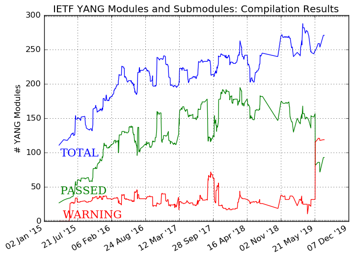