CHAPTER 2
Jumping in Headfirst, with Both Feet
In this chapter, you're going to start using Maya and get your groove on. This will be a quick primer on the Maya interface so you experience tasks right away. The next chapter will show you more details and provide additional explanations and a reference of how the entire Maya interface works.
This chapter will take you through the creation of a Solar System exercise and the mechanics of animating orbits. With this exercise, you'll dive into creating simple objects, setting keyframes, and stacking your animation to get planets and moons to orbit each other and the Sun. This will expose you to object creation, simple modeling, object components, pivot-point placement, grouping and hierarchies, basic keyframing, and timing.
Topics in this chapter include:
- You put the U in UI
- Project overview: the Solar System
- The preproduction process: planning
- Creating a project
- The production process: creating and animating the objects
- Hierarchy and Maya object structure
- The Solar System resumed
- Using the Outliner
- Outputting your work: playblasting
You Put the U in UI
Fire up your computer and let's get this project going. This section will introduce you to getting around the Maya user interface (UI). It may seem difficult at first, but it will make sense as you move along.
You'll find everything you ever wanted to know about the interface and more in Chapter 3, “The Maya 2012 Interface.” The overall goal of this chapter is to expose you to Maya UI basics as well as important scene creation and editing tools. You can consider the next chapter a debriefing of sorts, to fill in UI details that aren't covered in this chapter.
KEYBOARD AND SYMBOL CONVENTIONS USED IN THIS BOOK
The following terms are used throughout this book:
Click and LMB+click refer to a mouse click with the primary (left) mouse button.
RMB+click refers to a mouse click with the right mouse button.
MMB+click refers to a mouse click with the middle mouse button.
Shift+click indicates that you should hold down the Shift key as you click with the primary (left) mouse button.
Shift+select indicates that you're holding down the Shift key as you select the next object for multiple selections.
Right-click refers to clicking with the right mouse button.
The ![]() symbol next to a menu command indicates that you should click the box (
symbol next to a menu command indicates that you should click the box (![]() ) next to the menu command to open the options for that command.
) next to the menu command to open the options for that command.
A Quick Screen Roadmap
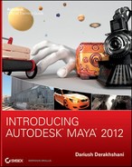
Let's get to the basics of how Maya is laid out (see Figure 2.1). Running across the top of the screen, right under the application's title bar, are the UI elements: the Main Menu bar, the Status line, and the Shelf. On a Macintosh system running OS X, note that the Main Menu bar runs at the very top of the screen, above the application's title bar.
Figure 2.1 shows the major parts of the UI. In the middle of the interface is the workspace, which is host to your panels (or Scene windows) and their menu options (known as views or viewports in some other 3D packages). This is where most of your focus will be; this is where you create and manipulate your 3D objects.
Click inside the large perspective view panel (named persp) with the mouse to activate the panel, highlighting its border slightly. Press the spacebar to display a four-panel layout, which gives you top, front, and side views as well as the perspective view. Press the spacebar in any of the panels to display a large view of that panel.
Figure 2.1 The initial Maya screen
To the right of the panels is the Attribute Editor/Channel Box. This is where most of the information (attributes) about a selected object is displayed and edited. Pressing Ctrl+A toggles between the Attribute Editor and the Channel Box. In short, the Attribute Editor gives you access to all of an object's attributes, whereas the Channel Box is a quicker display of the most commonly animated attributes of the selected object. The Attribute Editor is typically wider than the Channel Box, so you'll notice a shift in your view panels when you toggle between them. You can set Maya's preferences to treat the Attribute Editor as its own window, to prevent it from displaying on the right side of the UI. More on this in the next chapter.
Keys and Syntax in Maya
Maya is case sensitive in that it distinguishes between lowercase and uppercase letters. The conventions of this book will be to always print an uppercase letter to denote which key you must press, but to specify “Shift + the letter” when you must press the uppercase of that key. In other words, when we ask you to press the E key, for example, you should simply press the E key on your keyboard, lowercase. When an uppercase letter is called for, the book tells you to press Shift+E, requiring you to enter the uppercase letter E into Maya. Make sure your Caps Lock key is turned off.
SHORTCUTS TO NAVIGATING
Here's a rundown of how to navigate Maya. Keep in mind that the Option key is used on a Macintosh in place of the Alt key on a PC:
Alt+MMB+click Tracks around a window. Tracking moves left, right, up, or down in two dimensions; hold down the Alt key, press and hold the MMB, and drag the mouse.
Alt+RMB+click Dollies into or out of a view. A dolly moves the scene's camera in and out of the view, essentially zooming the view in and out. To dolly, hold down the Alt key, press and hold the RMB, and drag the mouse.
Scroll Wheel The scroll wheel, in addition to acting as a middle mouse button, can also dolly into or out of a view just like the Alt+RMB+click combination. Scrolling up dollies in, and scrolling down dollies out.
Alt+click Rotates or orbits the camera around in a Perspective window. Orbiting lets you get around your object to observe it from different vantage points. To orbit, hold down the Alt key and the LMB. This move is called a tumble. You can't tumble your view in an orthographic panel.
Alt+Ctrl+click and Drag Dollies your view into the screen area specified in your mouse drag. Hold down the Alt and Ctrl keys while using the LMB to outline a window in the panel to execute this bounding box dolly. This action is commonly referred to as a window zoom in other applications.
The ViewCube This part of a panel's interface lets you easily change your current panel view from, for example, perspective to side, top, and back to perspective with just a click. By clicking an area of the ViewCube (shown here), you can switch to other views inside that panel. Clicking one of the conical axis markers gives you an orthogonal view from that direction. Clicking the center square gives you the perspective view. You can toggle the ViewCube in the preferences by choosing Window ![]() Settings/Preferences
Settings/Preferences ![]() Preferences and clicking the ViewCube category.
Preferences and clicking the ViewCube category. 
Macintosh Keys The major difference in keys between a PC and a Mac, as far as Maya is concerned, is that the Option key on a Mac serves the same function as the Alt key on a PC. Although a few Ctrl key combinations in Windows are accessed via the Command key on a Mac, Mac users can generally use the Mac's Ctrl key for their key combinations just as PC users do.
Mouse Controls
Maya requires the use of a three-button mouse, even on a Macintosh system. The clickable scroll wheel found on most mice can be used as the third button by pressing down to click with the wheel. Scrolling the wheel lets you zoom into or out of a view panel.
In Maya, you press and hold the Alt key on a PC (or the Option key on a Mac) along with the appropriate mouse button to move in the view panel:
- The left mouse button (LMB) acts as the primary selection button and allows you to orbit around objects when used with the Alt key.
- The right mouse button (RMB) activates numerous shortcut menus and lets you zoom when used with the Alt key.
- The middle mouse button (MMB) used with the Alt key lets you move within the Maya interface panels, and the mouse's wheel can be used to zoom in and out as well.
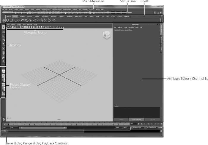
Figure 2.2 The Maya Manipulators
Making Selections
Selecting objects in a view panel is as easy as clicking them. If the object is displayed in Wireframe mode, its wireframe turns green while it's selected. If the object is displayed in a Shaded mode, the object's wireframe will appear around the object. Shaded mode is a way of seeing your objects in the view panel with a basic surface, as opposed to a wireframe that you can see through. You'll see this as you do the following exercise.
As you select an object, its attributes appear in the Attribute Editor or Channel Box on the right.
To select multiple objects, simply hold the Shift key as you click objects to add to your current selection. The previous selection's wireframe turns white, and the new selection is now green. If you press Ctrl+LMB (that is, press the Ctrl key and click) on an active object, you'll deselect it. To clear all of your current selections, click anywhere in the empty areas of the view panel.
Remember: Use Shift+click to select, and Maya adds to the current selection. Use Ctrl+click, and Maya deselects the object you clicked on.
Manipulating Objects
When you select an object and enable one of the transformation tools (tools that allow you to move, rotate, or scale an object), you'll see a Manipulator appear at or around the selected object. Figure 2.2 shows the three distinct and most common Manipulators for all objects in Maya: Move, Rotate, and Scale as well as the Universal Manipulator. You use these Manipulators to adjust attributes of the objects visually and in real time.
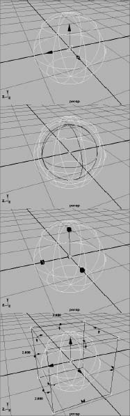
To activate a Transform tool, select an object and then click one of the Transform tool icons in the Tool Box, shown in Figure 2.3.
Try This Let's put some of this into action, shall we?
Choose Create ![]() NURBS Primitives
NURBS Primitives ![]() Sphere. Drag in a view panel anywhere on its grid to create a wireframe sphere, and then size it to your liking. In one of the view panels, press the 5 key on your keyboard, and the display of the sphere will become solid gray, as opposed to open wireframe. This is called Shaded mode. Press the 4 key to return to Wireframe mode.
Sphere. Drag in a view panel anywhere on its grid to create a wireframe sphere, and then size it to your liking. In one of the view panels, press the 5 key on your keyboard, and the display of the sphere will become solid gray, as opposed to open wireframe. This is called Shaded mode. Press the 4 key to return to Wireframe mode.
Press 4 for Wireframe mode; press 5 for Shaded mode.
With the sphere selected, select the Move tool (![]() ) from the Tool Box. The first Manipulator shown in Figure 2.2 should appear in the middle of the sphere. The three arrows represent the three axes of possible movement for the object.
) from the Tool Box. The first Manipulator shown in Figure 2.2 should appear in the middle of the sphere. The three arrows represent the three axes of possible movement for the object.
Red is for the X- axis, green is for the Y- axis, and blue is for the Z- axis. Cyan is for free movement in both axes of the active panel view.
Clicking any one of the three arrows lets you move the object only on that particular axis. The square in the middle of the Manipulator lets you move the object freely about the plane of the view panel, regardless of the axis. When you select a Manipulator handle for movement, it turns yellow. The Free Movement box in the center then turns back to its regular color, cyan.
Next, select the Rotate tool (![]() ) from the Tool Box, and you'll see the second Manipulator in Figure 2.2. The three colored circles represent the three axes of rotation for the object—red for X, green for Y, and blue for Z. Select a circle to rotate the object on that axis. The yellow circle surrounding the three axis circles lets you freely rotate the object on all three axes. The Free rotation handle also turns cyan when an axis handle is active.
) from the Tool Box, and you'll see the second Manipulator in Figure 2.2. The three colored circles represent the three axes of rotation for the object—red for X, green for Y, and blue for Z. Select a circle to rotate the object on that axis. The yellow circle surrounding the three axis circles lets you freely rotate the object on all three axes. The Free rotation handle also turns cyan when an axis handle is active.
Figure 2.3 The Transform tools in the Tool Box
Now, try selecting the Scale tool (![]() ) to see the third Manipulator in Figure 2.2. By selecting one of the axis handles and dragging the mouse, you can scale the object in a nonuniform manner in that axis. The middle cyan box scales the object uniformly on all three axes.
) to see the third Manipulator in Figure 2.2. By selecting one of the axis handles and dragging the mouse, you can scale the object in a nonuniform manner in that axis. The middle cyan box scales the object uniformly on all three axes.
Try selecting the Universal Manipulator (![]() ). This tool acts in place of all three Manipulators you just tried. Grabbing the familiar arrows translates the sphere. Selecting any of the curved arrows in the middle of the edges of the Manipulator box lets you rotate the sphere in that axis. Finally, selecting and dragging the cyan boxes in the corners of the Manipulator box lets you scale the sphere. If you hold down the Ctrl key as you drag, you can scale the sphere in just one axis.
). This tool acts in place of all three Manipulators you just tried. Grabbing the familiar arrows translates the sphere. Selecting any of the curved arrows in the middle of the edges of the Manipulator box lets you rotate the sphere in that axis. Finally, selecting and dragging the cyan boxes in the corners of the Manipulator box lets you scale the sphere. If you hold down the Ctrl key as you drag, you can scale the sphere in just one axis.
Go ahead and click around the interface some more. Create more primitive objects, and tool around a bit. Move around the view panels and see how it feels. Give the tires a good kick.
Enough chatting—let's jump into the Solar System exercise.
Project Overview: The Solar System
This project focuses on familiarizing you with the fundamentals of navigating Maya, object creation, hierarchy, and pivots, all of which are important concepts for scene manipulation and animation within Maya. In this exercise, you'll create and animate a simple simulation of our working Solar System. (You may have done this in school using coat hanger wire and Styrofoam balls.) This time-tested tutorial is great practice for getting used to object creation, hierarchies, scene manipulation, UI navigation, and working with objects and selections. It will show you how to set up hierarchies and give you experience in working with the proper nodes within a group to create hierarchically layered animation.
The Preproduction Process: Planning
Every smooth operation begins with a good plan. The more research and focused information you gather, the better off you'll be in your work. For this exercise, you need to find out where each of the planets is in relation to the Sun and to the other planets and also how many moons it has.
Starting with the Sun in the center, the planets in order are Mercury, Venus, Earth, Mars, Jupiter, Saturn, Uranus, Neptune, and Pluto. (We'll label Pluto a planet for old time's sake, even though it was reclassified as a “dwarf planet” by the scientific community in 2006.) All these planets actually orbit the Sun in ellipses, but we'll give them circular orbits for this exercise. Most planets have a number of moons that orbit them, and one, Saturn, has large rings that circle around it.
| Earth | 1 moon |
| Mars | 2 small moons |
| Jupiter | 16+ moons |
| Saturn | 3 large rings and 18+ moons |
| Uranus | 18 moons |
| Neptune | 8 moons |
| Pluto | 1 moon |
Creating and animating all those objects may seem overwhelming, but it's a great way to become comfortable with Maya and animation. Because the goal of the project is achievable without making every moon, you'll cut most of them out of your scene and make a maximum of two moons per planet.
The more you run this exercise, the clearer Maya's scene manipulation and hierarchy structure will become to you. Art is a marriage of inspiration, hard work, and practice.
Creating a Project
Projects are Maya's way of managing a scene's assets. A file and folder structure keeps your files organized according to projects. You'll have a project for the Solar System exercise.
Start by creating a new project for this assignment. Choose File ![]() Project
Project ![]() New to open the New Project window. (Figure 2.4 shows the Windows version; the Mac OS X version has the same fields.) Files are organized in a particular way in Maya. The top level of this organization is the Project folder. Within the Project folder are numerous file folders that hold your files. The two most important types are the Scenes and Images folders. The Scenes folder stores your scene files, which contain all the information for your scene. The Images folder stores images you've rendered out from your scene. As with clothing and other items around your house, keeping your files and projects organized is a good practice.
New to open the New Project window. (Figure 2.4 shows the Windows version; the Mac OS X version has the same fields.) Files are organized in a particular way in Maya. The top level of this organization is the Project folder. Within the Project folder are numerous file folders that hold your files. The two most important types are the Scenes and Images folders. The Scenes folder stores your scene files, which contain all the information for your scene. The Images folder stores images you've rendered out from your scene. As with clothing and other items around your house, keeping your files and projects organized is a good practice.
NAMING OBJECTS AND KEEPING THE SCENE ORGANIZED
In Maya and most other CG packages, keeping things organized and as clean as possible is more important than you probably realize. Picking up a scene from a disorganized colleague is annoying because it's very time consuming to figure out exactly what is in their scene and how everything works together. Many professional studios have strict naming procedures and conventions to minimize the confusion their artists may have when working in a pipeline. These procedures and conventions are beneficial because many artists will touch the same digital files and assets in the course of a production. Even if you're the only person who will ever see your scene in Maya, it's still a good idea to name and organize your objects. Get into the habit of naming your objects and keeping a clean scene. You'll waste a lot of time if you don't, and you'll be bombarded by dirty looks from other artists when they have to handle your cluttered scenes.
The scene files discussed in this chapter are included on the book's web page, www.sybex.com/go/introducingmaya2012. They are in a project layout explained in the following text. Copy the scene files on the web page for this project into your own Project folders after you create the project.
To create a new project, follow these steps:
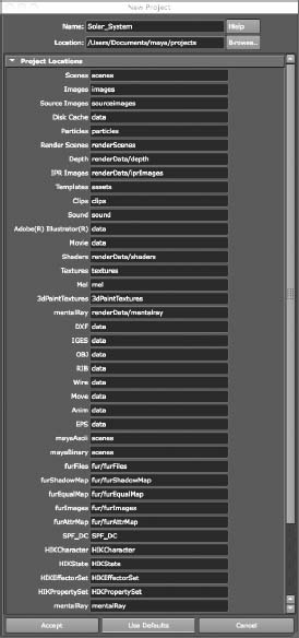
- In the Name field in the New Project window, enter Solar_System as the name for your project. In the Location box, type the location where you want to store your projects.
The default location for Windows XP, Vista, and Windows 7 is in the current user's My Documents folder: My Documentsmayaprojects; for Macs, the default location is Home (/Users/<yourname>) in the Documents/maya/projects/default folder. If you prefer, you can put projects in a folder on a secondary or external hard drive to keep them separate from your operating system; this allows for easier backup and is generally a safer environment.
- If you're using a Windows system, create a folder on your hard drive called Projects using Windows Explorer. If you're using a Mac, select a drive in the Finder and create a folder on the drive called Projects. In the New Project window, click the Browse button and select D:Projects (Windows) or <Hard Drive Name>/Projects (Mac) for the location. Maya will fill in all the other fields for you with defaults; just click the Use Defaults button. Click Accept to create the necessary folders in your specified location. Figure 2.5 shows the completed New Project window in Windows; except for the drive name, the values are the same on a Macintosh.
Figure 2.4 The New Project window
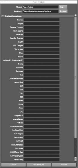
Figure 2.5 The completed New Project window
After you create projects, you can switch between them by choosing File ![]() Project
Project ![]() Set and selecting the new project. Maya will then use that project's folders until you switch to or create another project. You may also select a recent project by choosing File
Set and selecting the new project. Maya will then use that project's folders until you switch to or create another project. You may also select a recent project by choosing File ![]() Recent Projects. Maya by default will list four of your recent projects and scene files on the File menu for easy access.
Recent Projects. Maya by default will list four of your recent projects and scene files on the File menu for easy access.
DON'T FORGET TO SET YOUR PROJECT!
You should make sure to set your project before continuing with your work. The exercises in this book are based on projects, and you'll need to set your project whenever you start a new exercise—otherwise, the scene may not load properly or your files may not save to the proper locations for that project.
The Production Process: Creating and Animating the Objects
As discussed in Chapter 1, “Introduction to Computer Graphics and 3D,” production is typically divided into phases to make workflow easier to manage. In this project, you'll first create the Sun, the planets, and their moons; then, you'll animate their respective orbits and rotations.
Creating the Sun and the Planets
The first thing you're going to do is create the Sun and the planets. Follow these steps:
- Choose File
 New Scene (or press Ctrl+N). Maya asks if you want to save your current scene. Save the file if you need to, or click Don't Save to discard the scene.
 - By default, Maya's screen should begin in an expanded perspective view. Press the spacebar to enable the four-panel view. When you're in the four-panel view, press the spacebar with the cursor inside the top view panel to select and maximize it.
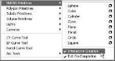
- To create the Sun, you need a primitive sphere. A primitive is a basic 3D shape. First, let's turn off a Maya feature called Interactive Creation that is on by default. Turning off Interactive Creation allows you to create the sphere at the center of the grid (the origin) without having to click and drag its size and then reposition it manually. Uncheck Create NURBS Primitives Interactive Creation to toggle it off, as shown in Figure 2.6. For more on how to create primitives with interactive feedback, see the section “Work Panels and Navigation” in Chapter 3.
- With Interactive Creation turned off, choose Create NURBS Primitives Sphere. Doing so places a NURBS sphere exactly at the origin—that is, at a position of 0,0,0 for X,Y,Z. This is good, because the origin of the workspace will be the center of the Solar System, too.
- Select the word nurbsSphere1 in the Channel Box to the right of the Maya UI (shown in Figure 2.7), and enter Sun to rename it. If you don't see the Channel Box in your Maya window, please refer to the section “Maya's Layout” in Chapter 3. Naming your objects right after creation is a good habit to develop. Doing so makes for a cleaner scene file and a more organized workspace. This is particularly important if anyone needs to alter your scene file; proper naming will keep them from getting frustrated when they work on your scene.
Figure 2.6 Turning off Interactive Creation
NURBS AND POLYGONS
NURBS and polygons are two types of geometry that you can create and edit in Maya. We'll explore the uses of each modeling type in Chapter 4, “Beginning Polygonal Modeling;” Chapter 5, “Modeling with NURBS, Subdivisions, and Deformers;” and Chapter 6, “Practical Experience.”
Figure 2.7 Renaming the sphere in the Channel Box

Always keep in mind that Maya is case sensitive. An object named “sun” is different from an object named “Sun.”
Maya typically uses an object-naming structure called a humpback style, where words are slung together without spaces. The first letter of a new word in the humpback name is capitalized. An example of humpback style is the name indoorPatioScene. Maya uses this structure when naming nodes, such as the node name nurbsSphere1.
- Choose the Scale tool in the Tool Box to activate the Scale Manipulator, and uniformly scale the Sun sphere up to about four times its creation scale of 1. (Make it a scale of about 4 in all three axes.) For more precision, you can do one of two things: You can select the sphere and enter a value of 4 in all three entry fields (the white window next to the attribute) for the Scale X, Scale Y, and Scale Z channels in the Channel Box shown on the left in Figure 2.8. Alternatively, you can enter a value of 4 in the Input box on the Status line along the top of the UI, as shown on the right of Figure 2.8. Don't worry; we'll take an in-depth look at both of these methods in the next chapter.
Figure 2.8 The Sun's Scale values in the Channel Box (left) and in the Input box (right).
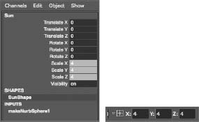
- After you enter the final value through either method, press Enter, and the sphere will grow to be four times its original size (at a scale of 1). When you enter the values in either the Channel Box or the Input box, a scale of 4 appears in all three fields, as shown on the right in Figure 2.8, and your Sun expands in size by a factor of 4. Entering exact values in the Channel Box or Input box is a way to scale the sphere precisely; using the Manipulator isn't as precise.
Creating the Planets
Next, you'll create the primitive spheres you'll be using for the planets. Leave Interactive Creation off, and follow these steps:
- Create a NURBS sphere for Mercury just as you did before, by choosing Create NURBS Primitives Sphere. A new sphere appears at the origin. Click its name in the Channel Box and change it to Mercury.
- Choose the Move tool from the Tool Box to activate the Move Manipulator, and move Mercury a few grid units away from the Sun in the positive X direction. (Click the red arrow and drag it to the right.) Leave about two grid units between Mercury and the Sun.
- Because Mercury is the second smallest planet and is tiny compared to the Sun, scale it down to 1 20 the size of the Sun, or type 0.2 in all three axes of scale if you choose to enter the values manually in the Channel Box.
- Repeat steps 1 through 3 to create the rest of the planets and line them up, placing each one farther out along the X-axis. Be sure to keep about two grid units of space between them. Scale each one proportionally as follows:
| Venus | 0.5 |
| Earth | 0.5 |
| Mars | 0.4 |
| Jupiter | 1.0 |
| Saturn | 0.9 |
| Uranus | 0.7 |
| Neptune | 0.7 |
| Pluto | 0.15 |
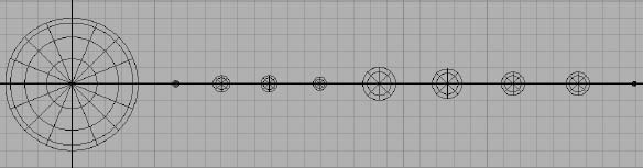
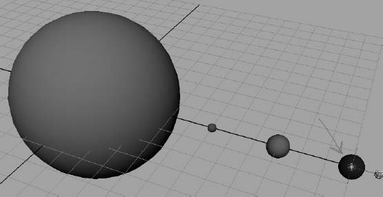
These proportions aren't exactly the same as those found in the real Solar System, but they will do nicely here. Figure 2.9 shows how your Solar System should look now.
Figure 2.9 All the NURBS spheres are lined up in place (top view).
No, Pluto isn't actually a planet anymore, but for nostalgia's sake, we'll include it here in our Solar System. Poor Pluto!
Using Snaps
Now is the perfect time to start using snaps. Some common snap icons are shown in Table 2.1. Snap icons are explained in greater depth in the next chapter. These icons run across the top of the UI just below the Main Menu bar, as shown here.
Table 2.1 Snap icons
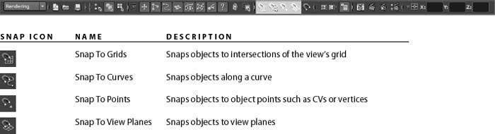
You use snaps to snap objects into place with precision, by placing them by their pivot points directly onto grid points, onto other object pivots, onto curve points, and so on. Here you'll reposition all the planets slightly to center them on the nearest grid line intersection:
- Select the first planet, Mercury. Choose the Move tool from the Tool Box, and toggle on grid snaps by clicking the Snap To Grids icon (
 ).
). - The center of the Move Manipulator turns from a square to a circle, signaling that some form of snapping is active. Grab the Manipulator in the middle by this circle, and move it slightly to the left or right to snap it onto the closest grid intersection on the X-axis.
- Select the remaining planets, and snap them all to the closest grid intersection on the X-axis, making sure to keep about two grid spaces between each of them. Because the Sun was created at the origin and you haven't moved it, you don't need to snap it onto an intersection.
SAVING MULTIPLE VERSIONS OF YOUR WORK AND INCREMENTAL SAVING
As you're working on a project, you may want to save multiple versions of your files at various stages of completion. When working in the professional world, you'll find that clients and art directors often reconsider animations you've created—sometimes, it seems, just to make you crazy. So, it's always good to keep as many versions of an animation as you can. Scene files are reasonably small, and hard disk space is inexpensive. Just keep your Scenes folder organized well—for example, by keeping older versions of scenes in separate subfolders—and you should have no problems.
Maya's Incremental Save feature makes a backup of your scene file every time you save your scene. To enable it, choose File ![]() Save Scene
Save Scene ![]() , and click the Incremental Save box. After you've done this, Maya will create a new folder within your Scenes folder with the name of your current scene file. It will then create a backup of your scene in that folder and append a number to the filename: for example, planets_001.mb. Every time you save your file, Maya will create a new backup until you disable the feature by choosing File
, and click the Incremental Save box. After you've done this, Maya will create a new folder within your Scenes folder with the name of your current scene file. It will then create a backup of your scene in that folder and append a number to the filename: for example, planets_001.mb. Every time you save your file, Maya will create a new backup until you disable the feature by choosing File ![]() Save Scene
Save Scene ![]() .
.
The scene files for the projects in this book are provided on the accompanying web page to give you a reference point for the major stages of each project. These files use a slightly different naming system than the names generated by Incremental Save (for example, the file on the web page is planets_v1.mb instead of planets_001.mb), so there is no risk of files overwriting each other.
For important real-world projects, you may decide to supplement the Incremental Save backups by using Save Scene As to create named files manually, perhaps following a similar naming system with a version number appended, at the stages where you've made significant changes. Whether you do this or use Incremental Save, it's a good idea to keep written notes about the differences in each version of a scene file so that whenever you make a significant change to a file, you have a record of your work.
If you prefer to name files manually, be sure to use an underscore (_) between the filename and version number instead of a space. Using spaces in your filenames can create problems with the software and operating system, especially when you're rendering out a scene.
Making Saturn's Ring
Now, create the ring for Saturn. To do so, follow these steps:
- Choose Create NURBS Primitives Torus to place a donut shape at the origin. Remember, Interactive Creation is turned off. You can also try creating the torus with the Interactive Creation option. In that case, click and drag the mouse to create the donut shape as you prefer. When you have a ring, use the Move tool to snap it to the same grid intersection as Saturn. This ensures that both the planet and its ring are on the same pivot point and share the same center.
- Select the torus shape you've created and name it Ring (if you haven't already done so) in the Channel Box.
- While the torus shape is still selected in the top view, press the spacebar to display the four-panel layout. Place the mouse cursor in the persp view, and press the spacebar to maximize the Perspective window.
- Press the F key to focus the perspective display on the ring and on Saturn. Pressing F centers and zooms in the panel on just the selected object(s).
- Press 5 to get into Shaded mode, and with the torus selected, press 3 to increase the resolution display for the ring. Display resolutions are achieved by pressing the 1, 2, or 3 key and are further explained in the next chapter. Pressing 3 gives you the smoothest view of the torus in the view panels. That's a good thing.
Figure 2.10 Changing the creation attributes of the NURBS torus in the Attribute Editor

- From the Tool Box, select the Scale tool, and scale the torus down to 0 or close to 0 in the Y-axis (the torus's height, in this case) to flatten it.
- You'll notice that the ring is too fat and is cutting into the planet. You need to edit the attributes of the ring to increase the inside radius of the donut shape and create a gap between the planet and the ring.
- Press Ctrl+A (Ctrl+A will also work on a Mac) to toggle the Attribute Editor if it's not on, and then click the makeNurbTorus1 tab to select its creation node (see Figure 2.10).
- Increase the Radius attribute to about 1.5, and decrease the Height Ratio attribute to about 0.25 to get the desired effect.
Now all your planets are complete, and you can move on to the moons.
Changing the original attributes or parameters of an object, as you've just done with Saturn's ring, is often referred to as parametric modeling.
Saving Your Work
Save your work, unless you like to live on the edge. Saving frequently is a critical habit to develop. Power failures and other unforeseen circumstances (such as your pet jumping onto your keyboard) may not happen often, but they do happen—and usually at the wrong time. (As mentioned in the sidebar “Saving Multiple Versions of Your Work and Incremental Saving,” Maya's Incremental Save feature makes it easy to maintain backups of your work.) Because you created this as a new project, the Save File window will direct you to the Scenes folder of that project. Save your scene as planets in the .mb (Maya Binary) format.
The file Planets_v1.mb in the Scenes folder of the Solar_System project on the web page shows what the scene should look like at this point.
Creating the Moons
For the planets with moons, create a new NURBS sphere for each moon. For simplicity's sake, create a maximum of only two moons for any planet. However, feel free to make all the moons for all the planets after you get a handle on this exercise.
The first moon will be Earth's. Use the top view to follow these steps:
- Create a NURBS sphere, and scale it to about half the size of Earth using the Scale tool. Visually estimate the size of the moon.
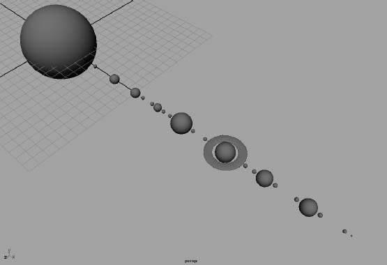
Figure 2.11 The planets and moons in position in perspective view
- Move the sphere to within half a unit of Earth, using the Move tool by the X-axis. There's no need to snap it to a grid point, so toggle off the Snap To Grids icon ().
- Repeat steps 1 and 2 for the remaining moons, placing them each within half a grid unit from their respective planets. When placing two moons, place them on opposite sides of the planet.
- After you're done with all the moons, their placements, and their sizes, select all the elements in the scene and press 3 to increase the display resolution on all the spheres. This gives you a smoother view of the NURBS spheres. When you're finished, you should have a scene similar to Figure 2.11 in perspective view. If you don't, it's clear Maya doesn't like you.
Applying a Simple Shader
To help distinguish one gray planet from another, attach simple shaders to each of the planets to give them color. Shaders, in short, are materials that give an object its particular look, whether it be color or a tactile texture. You can easily take care of this task using the Hypershade window. Follow these steps:
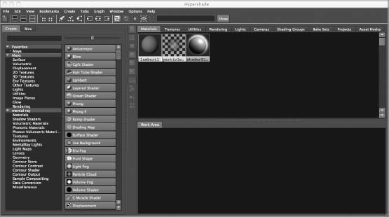
- Choose Window Rendering Editors Hypershade to open the Hypershade window. This window lists, and allows you to edit, all the shaders and textures in the scene. With this window, you create the look of your objects by assigning colors, surface properties, and so on. You'll notice three default (or initial) shader icons already loaded (see Figure 2.12). For more on the Hypershade window, see Chapter 3.
- In the Create Maya Nodes panel on the left of the Hypershade window and under the Surface heading, click the Lambert icon (a gray sphere) to create a new Lambert shader node. It appears in the top and bottom of the Hypershade window. Click this icon eight more times to create a total of nine Lambert shading groups in the Hypershade window.
Figure 2.12 The Hypershade window
- Click the first of the new Lambert nodes (lambert2) in the Hypershade window, and you should notice its attributes display in the Attribute Editor on the right of the UI. If you have the Channel Box displayed instead, double-click the shader's icon to open the Attribute Editor. At the top, replace lambert2 with Mercury_Color to identify this material as the one you'll use for Mercury.
- Name each of the remaining planets in your animation (Venus, Earth, Mars, Jupiter, Saturn, Uranus, Neptune, and Pluto).
To rename a node in the Hypershade window, you can also right-click the node's icon and choose Rename from the context menu that appears.
Again, keeping a well-named and -organized scene is critical to a smooth animation experience. It's much more of a chore to root through dozens of unnamed nodes to find the one you want. When you've finished naming all the material nodes, save your work.
SETTING KEYFRAMES
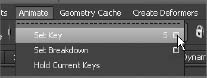
As with many other functions in Maya, you can set a keyframe in several ways. Switch to the Animation menu set by pressing F2. When you're first starting to learn Maya, the best way is to choose Animate ![]() Set Key r to display the Set Key Options box. Here, you're selecting the Option box for that menu item by clicking the little empty box to the right of the menu item. The Option box for any particular menu item allows you to set the options for that function. In this case, you're changing the options for the Set Key function.
Set Key r to display the Set Key Options box. Here, you're selecting the Option box for that menu item by clicking the little empty box to the right of the menu item. The Option box for any particular menu item allows you to set the options for that function. In this case, you're changing the options for the Set Key function.
If you choose Animate ![]() Set Key without first changing those options, Maya sets a keyframe for all the keyable attributes for the selected object. Although this may seem convenient, it makes for a sloppy scene, especially if the scene must be heavily animated.
Set Key without first changing those options, Maya sets a keyframe for all the keyable attributes for the selected object. Although this may seem convenient, it makes for a sloppy scene, especially if the scene must be heavily animated.
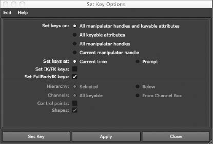
Having keyframes for attributes that may not actually be animated creates unnecessary clutter. In the Set Key Options box shown here, set the Set Keys On option to All Keyable Attributes instead of the default All Manipulator Handles And Keyable Attributes. Set Channels to From Channel Box instead of the default All Keyable. (These attributes will remain grayed out until you change to All Keyable Attributes.) Now, when you choose Animate ![]() Set Key, you'll set a keyframe only for the channels that you specify explicitly through the Channel Box, giving you greater control and efficiency. All you have to do is highlight the channel you want to keyframe in the Channel Box and then choose Animate
Set Key, you'll set a keyframe only for the channels that you specify explicitly through the Channel Box, giving you greater control and efficiency. All you have to do is highlight the channel you want to keyframe in the Channel Box and then choose Animate ![]() Set Key. Save your settings by choosing Edit
Set Key. Save your settings by choosing Edit ![]() Save Settings, and then click Close to close the dialog box.
Save Settings, and then click Close to close the dialog box.
After you've created the shaders, you can assign the appropriate colors to each of them according to the planet they represent:
Figure 2.13 Mercury's shading group in the Attribute Editor

- Double-click Mercury to open its Attribute Editor, if it's not currently open (see Figure 2.13).
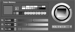
- To change the color of the shader, click the gray box next to the Color attribute. This opens the Color Chooser window, where you can choose a new color from the color wheel or by adjusting values with the HSV sliders. Because Mercury has a brownish red appearance, go with an orange color, such as in Figure 2.14 (take note of the HSV values).
- Change the remainder of the shaders as follows:
Mercury Orange-brown Venus Beige-yellow Earth Blue Mars Red-orange Jupiter Yellow-green Saturn Pale yellow Uranus Cyan Neptune Aqua blue Pluto Bright gray Figure 2.15 shows the shading groups.
Figure 2.14 The Color Chooser window
- Next, apply shaders to the planets. Select a planet in the Perspective window, and right-click its corresponding material in the Hypershade window to open a marking menu. Drag up to highlight Assign Material To Selection, and release the button to select it. You can also use the middle mouse button to drag the material from the Hypershade window to its planet. Leave the moons set to the default gray color. When you're finished, you should have a scene similar to Figure 2.16.
Now that you're finished, you're ready to animate. Save this file; if you enabled Incremental Save as recommended earlier, your file won't be replaced with subsequent saves. This way, if you get lost in your animation and need to start fresh, you won't have to re-create everything from scratch. You can return to a previous version of the file and start your animation over.
Figure 2.15 The Hypershade window with all the colored planet shading groups
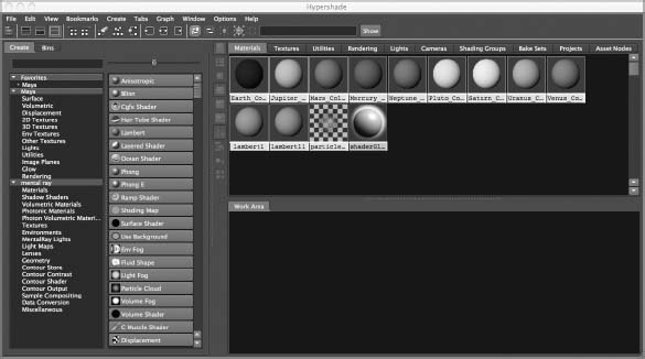
Figure 2.16 The shaded planets in perspective view

Creating the Animation
To begin this phase of the project, load the file Planets_v2.mb in the Scenes folder of the Solar_System project on the web page to your hard drive, or continue with your own scene file.
The animation you'll do for the orbits is straightforward. You'll rotate the planets around their own axes for their self-rotation, and then you'll animate the moons around the planets for their lunar orbits. Finally you'll make the planets and their moons orbit the Sun.
The premise of this exercise deals with hierarchy and pivot points. A pivot point is an object's center of balance of sorts. Every object or node that is created in Maya has a pivot point set at the origin. Because most objects, such as the spheres you created for the planets, appear at the origin upon creation, their pivot points are automatically centered.
When you move an object, as you've done to position the planets and moons, the pivot point moves with it. Therefore, all your planets' and moons' pivot points are already correctly positioned at the center of each planet and moon.
Now, you need to set up your scene file's animation settings:
- Press F2 to open the Animation menu set. Menu sets are groupings of menu headings in the Main Menu bar. They're organized according to the type of task at hand. You'll see the first several menu headings change when you switch from one menu set to another.
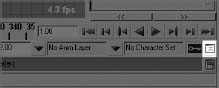
- At the bottom of the UI, you'll notice a slider bar (the Range slider) directly below the strip of numbers counting off the frames (the Time slider) in the scene. Using the Range slider, you'll set the length of your animation to go from 1 to 240. Enter 1 in the Scene Start Frame and Range Start Frame boxes (Figure 2.17). Enter a value of 240 in the Scene End Frame and Range End Frame boxes, also as shown in Figure 2.17.
Figure 2.17 The Time and Range sliders

- To the right of the Range slider, click the Animation Preferences icon (
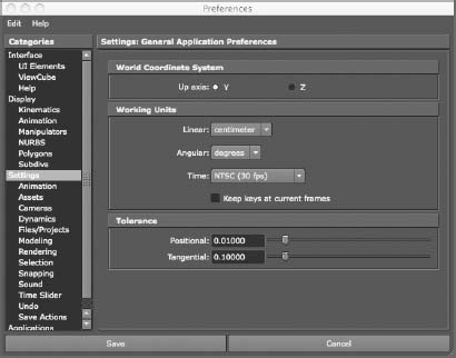
 ) (shown here in the context of the lower-right corner of the Maya screen), click Settings, and set Time to NTSC (30fps), which is 30 frames per second, or NTSC video speed. Also see Figure 2.18.
- Also verify that Up Axis is set to Y and not Z, as shown in Figure 2.18. This ensures that you've designated the Y-axis to be pointing “up” in the Perspective window or pointing out at you from the monitor in the top view. Y up, as it's called, is Maya's default, but it never hurts to make sure, especially if you're on a shared computer.
Choose Window ![]() Settings/Preferences
Settings/Preferences ![]() Preferences to open the Preferences window. Under Settings: Undo, make sure Undo is on (if it isn't already), and set Queue to Infinite. Setting Queue to Infinite takes a little more system memory, but it's worth it. With this configuration, you can undo (press Ctrl+Z, Command+Z (if you're on a Mac), or just Z) as many times as it takes to undo any blunders. To close the Preferences window, click Save.
Preferences to open the Preferences window. Under Settings: Undo, make sure Undo is on (if it isn't already), and set Queue to Infinite. Setting Queue to Infinite takes a little more system memory, but it's worth it. With this configuration, you can undo (press Ctrl+Z, Command+Z (if you're on a Mac), or just Z) as many times as it takes to undo any blunders. To close the Preferences window, click Save.
Figure 2.18 Set Time to 30fps in the Settings tab of the Preferences window.
Mercury's Rotation
Now you're ready to animate Mercury's rotation. Follow these steps:
- Select Mercury, and press E to activate the Rotate tool. The E key is the hotkey to invoke the Rotate tool in Maya; pressing it is the same as clicking the Rotate tool icon in the Tool Box, as you've been doing so far. Press F to focus on Mercury in the perspective view, or zoom in on it manually.
- Make sure you're on frame 1 of your animation range by clicking and dragging the Scrub bar (refer back to Figure 2.17) to place it at the desired frame. You can also manually type the frame value of 1 in the Current Frame box.
- For Mercury, you'll set your initial keyframe for the Y-axis rotation. Click the Rotate Y's attribute name in the Channel Box to select it (it's then highlighted in gray, as shown in Figure 2.19), and, in the Main Menu bar, choose Animate Set Key. This places a keyframe for a rotation of 0 in the Y- axis at frame 1 for the Mercury sphere. If you followed the advice in the sidebar “Setting Keyframes,” earlier in this chapter, only the Rotate Y attribute's Value box turns from white to orange to indicate that a keyframe exists for that attribute. If you left the Set Key command at its defaults, choosing Animate Set Key sets keys on all the attributes for the sphere, turning all their values orange in the Channel Box.
Figure 2.19 Setting the initial keyframe for Mercury's Y-axis rotation

- Using the Scrub bar in the Time slider, go to frame 240. Grab the Rotation Manipulator handle by the Y-axis (the green circle), and turn it clockwise a few times to rotate the sphere clockwise. You'll notice that you can rotate the object only so far in one direction before it seems to reset back to its original starting rotation. Rotate it as far as it will go, and release the mouse button. Then, click the Manipulator again, and drag to rotate the sphere as many times as necessary until you're satisfied.
- Choose Animate Set Key with the Rotate Y attribute still selected in the Channel Box. This sets a keyframe for the new Y-axis rotation at frame 240 for the Mercury sphere.
- To play back your animation, you can scrub your Time slider. Scrubbing is using the mouse to move the Scrub bar back and forth so you can watch the animation play back in a window. Click in the Time slider on the Scrub bar, hold down the left mouse button, and move your cursor from side to side to scrub in real time. You see Mercury rotating in your active view panel, if you set your two keyframes as described.
Clicking so many things just to set two keyframes may seem like a lot of work, but you're doing this the long way right now; you're not yet using any shortcuts or hotkeys. You'll start using those for the next planet.
You have the self-rotation for Mercury worked out. Mercury has no moon, so let's get Mercury orbiting the Sun.
Grouping Mercury for a New Pivot Point
You've learned that every object in Maya is created with a pivot point around which it rotates, from which or to which it scales, and which acts as the placement point for its X-, Y-, and Z- coordinates. To orbit Mercury around the Sun, the sphere must revolve around a pivot point that is placed in the middle of the Sun. If the pivot point for Mercury is already at the center of itself, how can you revolve it around the Sun?
One idea is to move its current pivot point from the center of itself to the center of the Sun. That would, however, negate Mercury's own rotation, and it would no longer spin around its own center, so you can't do that. You need to create a new pivot point for this object. This way, you have the original pivot point at Mercury's center so it can self-rotate, and you have a second pivot point at the Sun so that Mercury can revolve around that point around the Sun. You'll accomplish this by creating a new parent node above Mercury in the hierarchy. What does that mean?
In order not to get too confusing, we'll take time in the following section to introduce the concept of Maya object structure: nodes and hierarchies. Save your progress so far, and open a new blank scene. After this explanation, we'll resume the Solar System exercise.
Hierarchy and Maya Object Structure
Let's take a timeout from the Solar System exercise and look at how objects and hierarchies work in Maya. On top of everything that you see in Maya—its interface—is a layer you don't see: the code. The layer of code keeps the objects in Maya organized through a network of nodes. How you relate these nodes defines how you've built your scene. In short, using Maya is essentially programming your computer directly to create 3D objects and animation.
So, having a solid understanding of how Maya defines objects and how they interact is essential to an efficient and successful animation process. This involves getting an intrinsic understanding of how nodes relate, whether it's a straightforward parent-child hierarchy in which one affects the other directly or a more complicated script-driven expression connecting 15 attributes of several objects to simplify a task.
Understanding Nodes
At its core, Maya relies on packets of information called nodes, and each node carries with it a group of attributes that in combination define an object. These attributes can be spatial coordinates, geometric descriptors, color values, and so on. Taken together, an object's attributes define it and how it animates. You can define, animate, and interconnect any or all of these attributes individually or in concert, which gives you amazing control over a scene.
Nodes that define the shape of a surface or a primitive are called creation nodes or shape nodes. These nodes carry the information that defines how that object is created. For example, a sphere's creation node has an attribute for its radius. Changing that attribute changes the radius of the sphere at its base level, making it a bigger or smaller sphere. This is different than scaling the sphere as we've done with the planets so far. Shape nodes are low on the hierarchy chain and are always child nodes of transform nodes. The sphere listens to its creation node attributes first and then moves down the chain to its other nodes' attributes (such as position, rotation, or scale).
Not all primitives are created with shape nodes, so changes at the creation level may not be possible on certain objects; some objects are created without a creation node. When you create a new primitive or an object, make sure the History button (![]() ) is turned on in the Status line (see Chapter 3 for more about the Status line and its icons). If it displays a small red X in the icon, History is off, and the primitive will be created without a shape node.
) is turned on in the Status line (see Chapter 3 for more about the Status line and its icons). If it displays a small red X in the icon, History is off, and the primitive will be created without a shape node.
The most visible and used nodes are the transform nodes, also known as directed acyclic graph (DAG) nodes. These nodes contain all the transformation attributes for an object or a group of objects below it. Transformations are the values for translation (position), rotation, and scale. These nodes also hold hierarchy information about any other children or parent nodes to which they're attached. When you move or scale an object, you adjust attributes in this node.
Try This As an example of working with transform nodes, you can create a sphere and see what happens in the Attribute Editor as you adjust its position and size. Follow these steps in a new Maya scene:
- Press Ctrl+A to toggle the Attribute Editor on the right of the UI or to open it as its own window if you've set it up to do so in Maya's preferences. (Ctrl functions the same on a Mac as on a PC, so Mac users can also use their Ctrl key when called for in the text.)
The tabs along the top of the window let you switch between the nodes that are attached to this object. The current tab should be on the sphere's shape node, called nurbsSphereShape1. This node contains specific information about the object, but it isn't typically a node that you edit.
- Press W to select the Translate tool. With the sphere still selected, click the nurbsSphere1 tab in the Attribute Editor to access the sphere's transform node. Move the sphere a little in the X direction. Notice in the Attribute Editor that the Translate attribute for X has changed. You should also see the change in the Channel Box.
- Press R to select the Scale tool. R is the hotkey by default in Maya for the Scale tool and is the same as clicking the Scale tool icon in the Tool Box (
 ). Scale the sphere uniformly, meaning equally, in all directions by clicking and dragging the Center Manipulator handle (the cyan box). Notice that the Scale X, Scale Y, and Scale Z attributes of the sphere change in the Attribute Editor. In the Attribute Editor, enter 1.0 for the X, Y, and Z Scale values to reset the sphere back to its original size.
 - In the creation node of makeNurbsSphere1, change the radius from 1.0 to 2.0. The sphere doubles in size because its radius is doubled. Switch back to the transform node (nurbsSphere1), and note that the Scale X, Scale Y, and Scale Z attribute values are unchanged. This is because you affected the size of the sphere through its Radius attribute in the creation node at its root level, not through the Scale attributes in a higher node. Any changes you make to the Scale attributes take effect after changes in the lower node. This is a perfect example of how one node's output (here, the Radius attribute) changes another node.
Parents and Children
A parent node is simply a node that passes its transformations down the hierarchy chain to its children. A child node inherits the transforms of all the parents above it. So, by using hierarchies for the Solar System exercise, you'll create a nested hierarchy of parents and children to animate the orbital rotation of the nine planets and some of their moons.
By creating parent-child relationships, you can easily animate the orbit of a moon around a planet while the planet orbits the Sun. With the proper hierarchy, the animation of the planet orbiting the Sun automatically translates to the moon. In effect, the planet takes the moon with it as it goes around the Sun.
Child nodes have their own transformations that can be coupled with any inherited transforms from their parent, and these transformations affect them and any of their children down the line.
Figure 2.20 A simple hierarchy in both the Outliner and Hypergraph windows
The revolution of one of the planets around the Sun takes into account its moons, but those moons can have their own animation to spin themselves around their planets. You're about to experience this firsthand as you continue the Solar System exercise. The more you hear about these concepts in different contexts, the easier they will be to master.
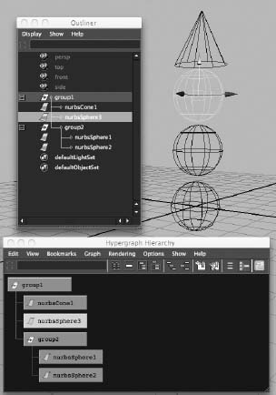
Figure 2.20 shows the Outliner and Hypergraph views with a simple hierarchy of objects for your reference. The Outliner and Hypergraph show you the objects in your scene in an outline and flowchart format, respectively. Both of these windows allow you to access the different levels of nodes (the hierarchy) in a scene and are discussed further in Chapter 3.
A top parent node called group1 holds its children nurbsCone1, nurbs-Sphere3, and the nested group node group2. The node group2 is the parent node of nurbsSphere2 and nurbsSphere1.
The Solar System Resumed
If you still feel a little unsure about nodes and hierarchies, take the time to reread the previous section and try the short exercise again. You'll practice these concepts as you resume the Solar System exercise. By the time you've finished this exercise, you'll have a strong sense of how hierarchies work in Maya, although you should feel free to repeat the entire exercise if you think that will help you master hierarchies. Understanding nodes and hierarchies is important to animating in Maya.
If you're new to CG animation, take your time with the following section.
Animating Mercury's Orbit Around the Sun
Load up your scene from where you last saved it. When you left off, you had created the self-rotation animation for Mercury and were about to create a second pivot point for the planet to orbit around the Sun by creating a new parent node for the Mercury sphere.
To create a new pivot point by making a new parent node, follow these steps:
- With Mercury selected, press E for the Rotate tool, and then choose Edit Group from the Main Menu bar. The Channel Box displays attributes for a new node called group1. Notice that nothing about the Mercury sphere changed, except that the Rotation Manipulator handle jumped from where it was originally centered on Mercury all the way back to the origin, where the zero points of the X-, Y-, and Z-axes collide. Figure 2.21 shows the new Mercury group and its new pivot location.
Figure 2.21 Grouping Mercury to itself creates a new pivot point at the origin.

You just created a new Maya object by grouping Mercury to itself. In doing so, you also created a second pivot point for Mercury, in effect, which was placed by Maya at the origin by default. Because an object's Manipulator always centers on its pivot point when it's selected, Mercury's Rotate Manipulator jumped to the origin when the new parent node became selected upon its creation. That is fortunate for you, because that happens to be the center of the Sun—exactly where you need it to be for Mercury to orbit the Sun properly.
- Without unselecting Mercury, click group1 in the Channel Box, and change the name of this new group to Mercury_Orbit. It's important to make the distinction between node names so you never get confused. Now you know that the Mercury node is the planet sphere itself, whereas Mercury_Orbit is the name of the new parent node, with which you'll orbit Mercury around the Sun.
- Click anywhere in an empty space in your view window to unselect Mercury_Orbit. Try selecting it again. Notice that when you click Mercury, you select only the planet and not the new parent node Mercury_Orbit, the group that has its pivot point at the center of the Sun. This happens because you're in Object Selection mode (a.k.a. Object mode). To select the group Mercury_Orbit, you need to switch into Hierarchy mode by toggling its icon (
 ) on the Status line at the top of the UI, as shown in Figure 2.22. Make sure you switch back to Object mode by clicking its icon (
 ) in the Status line. For more on selection modes, see Chapter 3.
Figure 2.22 Toggling on the Hierarchy mode
- Go back to frame 1 of your animation. Set a keyframe for Mercury_Orbit's Rotate Y attribute by selecting its name in the Channel Box and then choosing Animate Set Key from the Main Menu bar.
- Go to frame 240, grab Mercury_Orbit's Rotate Manipulator handle by the greenY -axis, and spin it around the Sun twice in either direction. (It doesn't matter if you go clockwise or counterclockwise.) You can also enter 720 (or −720 Object Selection mode to go in the other direction) in the Rotate Y attribute field in the Channel Box.
- Choose Animate Set Key to set a keyframe at frame 240 for Mercury_Orbit. Scrub your animation to play it back.
Does that make good sense? You'll have the chance to do this a few more times as you animate the other planets and their moons. However, if you still find yourself a little fuzzy on this concept (which is perfectly normal), repeat the steps to animate Mercury in a new scene file if need be. One down, eight to go.
Creating Venus
For your next planet, Venus, follow the same procedure as for Mercury's self-rotation, and animate it so that it rotates about itself. Then, create a new pivot point (placed by default at the origin) by grouping Venus to itself to create a new parent node for that sphere, and call the new parent node Venus_Orbit. Last, animate Venus_Orbit to revolve around the Sun just as you did with Mercury_Orbit in the previous steps.
Earth and the Moon
Now you need to animate the third planet, the Earth, in much the same way, except that this time there will be the added complication of a moon. In addition, instead of choosing Animate ![]() Set Key to set your keyframes, you'll use the keyboard hotkey S. (The Earth? Hey, I can see my house from here!)
Set Key to set your keyframes, you'll use the keyboard hotkey S. (The Earth? Hey, I can see my house from here!)
Whenever you press S when an attribute is highlighted in the Channel Box, you're essentially choosing Animate ![]() Set Key. In the Set Key Options box, be sure you've changed Set Keys On to All Keyable Attributes instead of the default All Manipulator Handles And Keyable Attributes. Also make sure you've set Channels to From Channel Box instead of the default All Keyable, as mentioned in the earlier sidebar.
Set Key. In the Set Key Options box, be sure you've changed Set Keys On to All Keyable Attributes instead of the default All Manipulator Handles And Keyable Attributes. Also make sure you've set Channels to From Channel Box instead of the default All Keyable, as mentioned in the earlier sidebar.
To animate Earth and the Moon, follow these steps:
- Select Earth, and give it its self-rotation animation as you did for Mercury. But this time, select the rotation channel names in the Channel Box and press S, instead of choosing Animate Set Key to set rotation keyframes. Again, if you left the Animate Set Key
 at its defaults, pressing S sets keys for all attributes. But if you followed the advice given previously in the sidebar, only the selected channels are keyframed.
 - Select the Moon, and give it its self-rotation animation by spinning it around itself and keyframing it as you've just done with Earth.
- To spin the Moon around Earth, do what you did earlier in this chapter to spin a planet around the Sun: group the Moon to itself by choosing Edit Group, and name the new parent node Moon_Orbit.
This time, however, you need the pivot point to be at the center of Earth and not at the center of the Sun object, where it is currently. Follow these steps:
- Turn on the grid snap, and then press the Insert key to activate the pivot point. If you're using a Macintosh, press the Home key. The Moon's Manipulator changes from a rotation handle to the Pivot Point Manipulator. This Manipulator acts just like the Move Manipulator, but instead of moving the object, it moves the object's pivot point.
- Grab the yellow circle in the middle of the Manipulator, and move the pivot point to snap it to the grid point located at the center of Earth (see Figure 2.23).
Figure 2.23 Moving the Moon's pivot point to the center of Earth
- Press the Insert key again (or the Home key on a Macintosh) to return to the Rotation Manipulator for Moon_Orbit. At frame 1, set a keyframe for the Moon's Y-axis rotation. Then, at frame 240, rotate the Moon about the Y-axis and set a keyframe. Return to frame 1.
Grouping the Moon with Earth
To animate Earth's orbit of the Sun, you need to make sure the Moon will also follow Earth around the Sun. Instead of just selecting Earth and grouping it to itself as you've done for the other two planets, you need to include the Moon_Orbit node in that group. Follow these steps:
- Select Earth. Shift+click the Moon_Orbit group while in Hierarchy mode () to make sure you get the topmost node of the Moon, and then choose Edit Group. Name this new parent node Earth_Orbit. Remember, when you select just Earth or the Moon in Object mode (), the Earth_Orbit node isn't selected. If you select Earth and then Shift+click the Moon, you select both objects, but you still don't select the parent node Earth_Orbit, which is the group that contains both these objects and has its pivot point at the center of the Sun. Make sure you select the right group. Keep an eye on where the Manipulator is when you make your selection. If you have the Earth_Orbit node selected, its Manipulator should be in the middle of the Sun. We'll deliberately illustrate this mistake and its consequences when you animate Pluto a little later.
Make sure you use Hierarchy mode (
) when you click the moon object to select Moon_Orbit and not just the moon sphere. Otherwise, you'll lose the animation of the Moon orbiting Earth. - Set a keyframe for Earth_Orbit's Rotate Y attribute at frame 1 by highlighting Rotate Y in the Channel Box and pressing S for the Set Key command. This assumes you've changed the defaults in Animate Set Key as discussed in the earlier sidebar.
- Go to frame 240, spin Earth and the Moon around the Sun a few times in whichever direction and for however many revolutions you want, and set a keyframe at frame 240 as well.
Now the first three planets are going around themselves and around the Sun, with a moon for the Earth. If you haven't been saving your work, save it now. Just don't save over the unanimated version from earlier.
Creating the Other Planets' Moons
Repeat this animation procedure for the remaining planets and moons, but leave out Pluto for now. (Poor Pluto: first it loses out on being a planet, and now it has to wait for last.)
If you find that one of your moons is left behind by its planet or that it no longer revolves around the planet, you most likely made an error when grouping the moon and planet. Undo until you're at the point right before you grouped them, and try again. If that still doesn't work, start over from the earlier version of the file you saved just before you began animating it. You'll learn how to fix it in the section “Using the Outliner,” later in this chapter.
Auto Keyframe
You can also use the Auto Keyframe feature when animating the planets and moons. Auto Keyframe automatically sets a keyframe for any attribute that changes from a previously set keyframe. For example, an initial keyframe for an attribute such as Y-Axis Rotation needs to be set at some point in the animation. The next time the Y-Axis Rotation is changed, Maya will set a keyframe at the current frame automatically.
To turn on Auto Keyframe, click the Auto Keyframe icon (![]() ), which is to the right of the Range slider. When the icon is red, Auto Keyframe is active.
), which is to the right of the Range slider. When the icon is red, Auto Keyframe is active.
To use Auto Keyframe to animate the moon orbiting Mars, follow these steps:
- Turn on Auto Keyframe.
- Start at frame 1. Select Mars's moon, and set a keyframe for its Y-axis orbit by highlighting Rotate Y in the Channel Box and pressing S.
- Go to frame 240. Revolve the moon around Mars several times in a direction of your choosing. Maya automatically sets a frame for Y rotation at frame 240. Save your file.
USE CUBES INSTEAD OF SPHERES
Feel free to create the planets and moons as cubes instead of spheres. That way, you can see each of their individual rotations much more easily, so you can tell whether the animation is working properly for you.
Using the Outliner
The Outliner is an outline format listing of all the objects and nodes in your scene. For an in-depth look at the Outliner, see Chapter 3. For now, let's look at how to use the Outliner to illustrate the hierarchies for the planets and moons. When all is good and proper, the Outliner should look like Figure 2.24. Choose Window ![]() Outliner to open the Outliner window and take a peek at what you have. If you haven't yet properly named everything, including the moons, take this opportunity to do so by double-clicking a name in the Outliner and entering a new name.
Outliner to open the Outliner window and take a peek at what you have. If you haven't yet properly named everything, including the moons, take this opportunity to do so by double-clicking a name in the Outliner and entering a new name.
Let's look at the planet Mars and its layout in the Outliner to better understand the hierarchy for all the planets. All the other planets should be laid out exactly like Mars (except the planets that have just one or no moons).
Figure 2.24 The Outliner view of the planet hierarchies
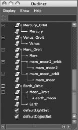
At the bottom of the hierarchy are Mars's two moons, mars_moon and mars_moon2. Each of those moons is spinning on its own pivot point. You grouped each moon to itself, created the mars_moon_orbit and mars_moon2_orbit nodes, and placed their pivot points at the center of Mars to animate their orbits around Mars.
Mars is spinning on its own pivot point, but it needed another pivot point to be able to orbit the Sun. Because you had to make the moons go with it around the Sun, you selected Mars, mars_moon_orbit, and mars_moon2_orbit (the top nodes of the moons that circle the planet Mars) and grouped them all together, placing that pivot point at the center of the Sun. You called this node Mars_Orbit. This is the parent node because it's the topmost node for this group. Wherever this parent node goes, the child nodes that are under it will follow.
Hierarchies such as this are a cornerstone of Maya animation. It's imperative that you're comfortable with how they work and how to work with them. If you find yourself scratching your head even a little, try the exercise again. A proper foundation is critical. Remember, this learning 3D thing isn't easy, but patience and repetition help a lot.
Correcting Hierarchy Problems Using the Outliner
One of the most common problems you'll run into with this project is a planet revolving around the Sun without its moon. To illustrate how to fix it using the Outliner, as opposed to undoing and redoing it as suggested earlier, the following steps will force you to make this error with Pluto. Usually, people learn more from mistakes than from doing things correctly.
Go to Pluto, start the same animation procedure as outlined earlier, and then follow these steps to force an error:
- Create Pluto's own self-rotation by spinning it around itself and keyframing as before.
- Do the same for Pluto's moon's rotation.
- Group the moon to itself, and grid-snap the pivot point at the center of Pluto to create the moon's orbit of Pluto.
When Pluto's moon (pluto_moon) is orbiting Pluto, you're ready to group the moon's orbit and Pluto together to create an orbit of the Sun for both.
- Here is where you make your mistake. In Object mode, select the sphere for Pluto's moon, and select the sphere for Pluto. Your error is that you're remaining in Object mode instead of switching to Hierarchy mode.
- Choose Edit Group to group them together, and call that new node Pluto_Orbit (following the naming convention you used for the others).
- Animate Pluto_Orbit revolving around the Sun.
- Play back the animation.
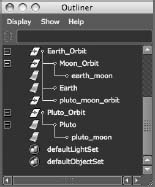
Notice that the moon is no longer orbiting the planet. This is because you didn't include pluto_moon_orbit in your group Pluto_Orbit. The animation of the moon going around Pluto is stored in that node, and because it's no longer attached to Pluto_Orbit, there's no moon orbit of Pluto.
Figure 2.25 shows the hierarchy of Pluto and how it's different from that of the other planets: the moon's orbit node has been left out of the group. (Earth has been expanded as a contrasting example.)
Figure 2.25 Pluto's incorrect hierarchy
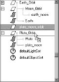
Using the Outliner, you can easily fix this problem. Place the pluto_moon_orbit node under the Pluto_Orbit node. Go to frame 1 of the animation, grab the pluto_moon_orbit node in the Outliner, and use the middle mouse button to drag it to the Pluto_Orbit node so that it has a black horizontal line above and below it to show a connection, as in Figure 2.26.
You've just grouped pluto_moon_orbit under Pluto_Orbit, a practice known as parenting. Now you need to parent pluto_moon under pluto_moon_orbit as well. Use the middle mouse button to drag pluto_moon onto pluto_moon_orbit. When you play back the animation, you'll see that the moon is revolving around the planet, while at the same time Pluto and the moon are orbiting the Sun. Now that you've corrected Pluto's layout in the Outliner, it's similar to the layouts for the other properly working planets.
Figure 2.26 Regrouping objects in the Outliner
The file Planets_v3.mb in the Scenes folder of the Solar_System project on the web page will give you an idea of how this project should look. The first five planet systems are grouped and animated as a reference, leaving the final four for you to finish.
You can add objects to a group by MMB+dragging their listing onto the desired parent node in the Outliner. You can also remove objects from a group by MMB+dragging them out of the parent node to a different place in the Outliner.
GROUPING TERMINOLOGY
Grouping terminology can be confusing. Grouping Node A under Node B makes Node A a child of Node B. Node B is now the parent of Node A. Furthermore, any transformation or movement applied to the parent Node B will be inherited by the child Node A.
When you group Node A and Node B, both nodes become siblings under a newly created parent node, Node C. This new node is created just to be the parent of Nodes A and B and is otherwise known as a null node. To group objects, select them and choose Edit ![]() Group. Parenting nodes together places the first selected node under the second selected node. For example, if you select Node A, Shift+select Node B, and then choose Edit
Group. Parenting nodes together places the first selected node under the second selected node. For example, if you select Node A, Shift+select Node B, and then choose Edit ![]() Parent, Node A will group under Node B and become its child. This is the same procedure as MMB+dragging Node B to Node A in the Outliner, as you did with Pluto's moon and Pluto itself.
Parent, Node A will group under Node B and become its child. This is the same procedure as MMB+dragging Node B to Node A in the Outliner, as you did with Pluto's moon and Pluto itself.
Outputting Your Work: Playblasting
What's the use of animating all this work and not being able to show it? There are several ways of outputting your work in Maya, most of which involve rendering to images. One faster way of outputting your animation in a simple shaded view is called playblasting. Playblasting creates a sequence of images that play back on your computer at the proper frame rate. Only if your PC is slow, or if you're playblasting a large sequence of frames, will your playback degrade. In this case, playblasting 240 frames shouldn't be a problem.
A playblast, as it's called in Maya, outputs the view panel's view into an image sequence or AVI movie. You can also save the image sequence or AVI to disk if you like. Playblasting is done mainly to test the look and animation of a scene, especially when its playback is slow within Maya.
When you have your Solar System animated, output a playblast by following these steps:
Figure 2.27 Selecting Playblast
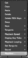
- With your animation completed, click in the Perspective panel to make it active in the four-panel layout (don't maximize the Perspective window). Press 5 to enter Shaded mode.
- RMB+click in the Time slider, and select Playblast from the menu, as shown in Figure 2.27. The Option box is shown for the Playblast options in Figure 2.28.
Figure 2.28 The Option box for creating a Playblast preview
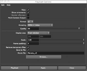
- In the Playblast options, set the Format to avi (displayed as qt for QuickTime when using a Macintosh) and the Display Size to From Window. Check the Save To File option, and give your Playblast a name. Set Scale to 1.0.
- Because you checked the avi (or qt on a Mac) option, Maya runs through the animation and creates an AVI movie file on a PC or a QuickTime movie file on a Mac that is based on the Shaded-mode appearance of the currently active view panel (which should be the Perspective panel). Because you also checked the Save To File option, the movie file is saved to disk. By default, it's saved to the Images folder for the Solar_System project you created on your hard drive. You can also click the Browse button to store the playblast video file anywhere you like. For now, click Browse, and place the file on your desktop. Click the Playblast button.
- When Maya runs through the animation, Windows Media Player on Windows and QuickTime on a Mac (or whatever your default movie player is set to in your OS) automatically opens and plays the move file of the animation at the proper speed of 30fps, as shown in Figure 2.29. Now you can share your animation with others without having to open Maya and play it back in the scene.
When you're creating a playblast, make sure you don't cover the view panel with any other windows, such as an Internet browser, as you wait for the animation to complete. Doing so may create a display error in the playblast output. It's best to allow Maya to complete the playblast before you use the system again.
Figure 2.29 Creating a playblast movie file is easy.

Summary
In this chapter, you learned how to start working in Maya by getting around the interface a bit and learning how to navigate the UI. Then, you began working by creating a new project, creating basic objects such as primitives, and placing objects in the scene. You learned how to place pivot points for objects and how to use snaps to place points precisely. You had some experience with the Channel Box and Attribute Editor to set an object's attributes. You then went on to create simple shaders for your objects and set keyframes to animate a Solar System. You explored object hierarchy and grouping conventions to organize and set up your scene better, and finally you learned how to output a basic playblast video file of your completed animation.
The planet animation you created is based on a system of layering simple actions on top of each other to achieve a more elaborate result. If you work slowly and in segments, animation is more straightforward to produce and generally of higher quality. Much of your time in actual animation, as opposed to setup or modeling, will be spent adjusting the small things. These small things give the scene life and character. You'll find that finishing 85 percent of a scene will take about 15 percent of the time. The remaining 85 percent of the time goes into perfecting the final 15 percent of the scene.