
CHAPTER 6
Practical Experience
It's time to put what you've learned so far into action. In this chapter, you'll build a toy called the red wagon. The wagon project uses poly and NURBS modeling techniques to give you some practical experience with a larger project. Topics in this chapter include:
- Beginning the Wagon project
- Modeling the side panels
- Creating the wagon body
- Modeling the wheels
- Making the wood railings
- Adding extra details
Beginning the Wagon Project
Download the entire RedWagon project folder structure from the book's companion web page (www.sybex.com/go/intromaya2012) to your computer's hard drive and set your project to that location.
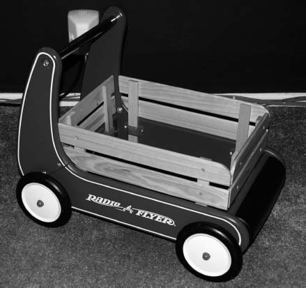
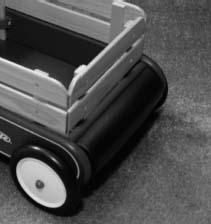
Figure 6.1 shows the red wagon you'll be modeling first in this chapter. There's certainly enough detail in this object to make it a good exercise, but it won't be difficult to complete. You can always come back to this exercise to add more of your own detail or even redesign it for more challenge, which is something I highly recommend.
Study the wagon closely to get a good idea of what you'll be modeling.
Using Reference Planes
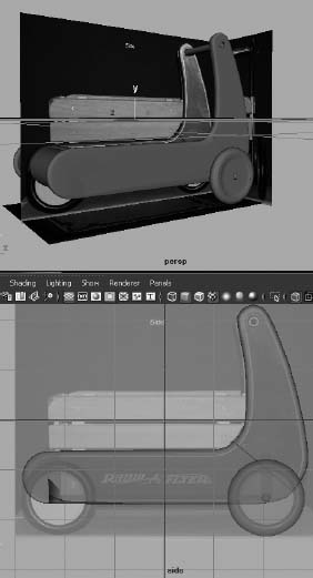
References aren't just for fun! You can also import images into Maya to work directly on the reference. For a model like this, it's best to create three different image views of the model (front, side, and top) to give you the most information as you build the model. The first step, of course, is to take pictures of your intended model from these three angles. Figure 6.2, Figure 6.3, and Figure 6.4 show photos taken of the front, side, and top views of the wagon.
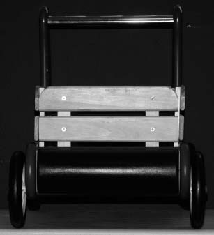
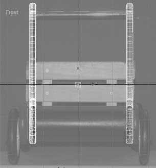
Figure 6.2 The wagon's front view
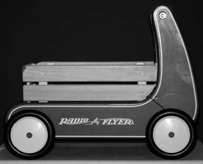
Figure 6.3 The wagon's side view
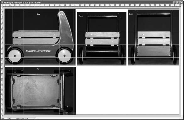
The trick here is to bring the photos into an image-editing program, such as Adobe Photoshop, and scale the images to line them up as shown in Figure 6.5. The figure has the added benefit of a view of the wagon taken from the back. The images have been copied and pasted into a larger frame, and grid lines are used to line up the major portions of the wagon, such as its wheels.
Keep in mind that when you take a photo, in most cases, there will be perspective shift or parallax in the image. Because of that shift, the different views of the same object will never exactly line up. As you can see in Figure 6.5, the height of the wagon doesn't line up between the front view and the back view, even though all the other major elements of the wagon are in alignment. This is due to perspective shift. Because the handle of the wagon is farther back from the lens of the camera in the front view, it appears lower in the frame than the handle in the back view.
Figure 6.4 The wagon's top view

Complete accuracy isn't what you're after in this situation. You just want to have a reasonable reference, and this will be more than adequate. Now, you'll import the images and create the model reference planes on which to work.
Figure 6.5 The views of the wagon roughly lined up in Photoshop
Creating Reference Planes for the Images
The reference views of the wagon have already been created for you. You can find them in the Sourceimages folder of the RedWagon project. They're shown in Table 6.1.
Table 6.1 Reference views and sizes

Why is the image resolution important? Well, it's not so much the resolution of the photos, but rather the aspect ratio of each image. To properly map these images onto the planes you'll use in Maya, each plane has to be the same ratio in scale as its image. For example, an image that is 100 × 50 pixels has an aspect ratio of 2:1 and is, therefore, a wide horizontal rectangle. For it to map properly, the plane on which it's mapped in Maya must also have a scale ratio of 2:1, so that it's also a wide horizontal rectangle. Otherwise, the image may distort. The more accurate your model needs to be, the more accurate your photos and their planes need to be.
You'll need to create three planes for each of the three views. First, make sure Interactive Creation is turned off, and then follow these steps:
- In the Front view panel, create a polygonal plane by choosing Create
 Polygon Primitives Plane
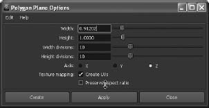
  . This plane is for the front image, so in the Options box set Axis to Z, Width to 0.912, and Height to 1.0. Make sure the check box for Preserve Aspect Ratio is deselected, as shown in Figure 6.6. Setting Axis to Z will place the plane properly in the front view.
Figure 6.6 Creating a plane for the top view
- Switch to the Side view panel. Create a second plane, this time with Width of 1.235 and Height of 1. Set Axis to X, and make sure the Preserve Aspect Ratio check box is not checked.
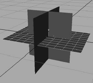
- Switch to the Top view panel. Create a third plane with Width of 1.49, Height of 1, and Axis set to Y. Make sure the Preserve Aspect Ratio box is still unchecked. Your Perspective panel should look like Figure 6.7.
Now that all three image planes have been created with the proper aspect ratios, you're ready to map the photos to them to create the reference for the model.
Mapping the Reference Planes
To map the photos of the wagon to the reference planes, follow these steps:
- Open the Hypershade (Window Rendering Editors Hypershade). Open a file browser, and navigate to the Sourceimages folder of the RedWagon project on your hard drive.
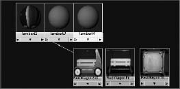
- Click the first image in your file browser, and drag it into the work area of the Hypershade window to import the file image. Drag the other two images into the Hypershade, as shown in Figure 6.8.
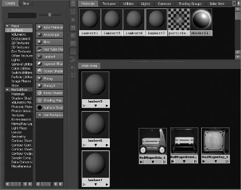
- Before you can assign the images to their respective planes, you must create shaders for each of the planes. In the left panel of the Hypershade window, click the Lambert icon three times to create three new Lambert shaders, as shown in Figure 6.9. For more information about shaders and texturing, see Chapter 7, “Maya Shading and Texturing.”
- While still in the Hypershade work area and while holding down the Ctrl key, MMB+drag the side view photo swatch onto the first Lambert shader icon. Maya automatically maps the image to the color of the Lambert shader, as shown in Figure 6.10. You can also MMB+drag the image to the Lambert Shader icon and then choose Color from the context menu that appears.
Figure 6.7 The three view planes are ready.
- Ctrl+MMB+drag the other two images onto their respective Lambert shaders to connect them.
Figure 6.8 Importing the photos into the Hypershade window
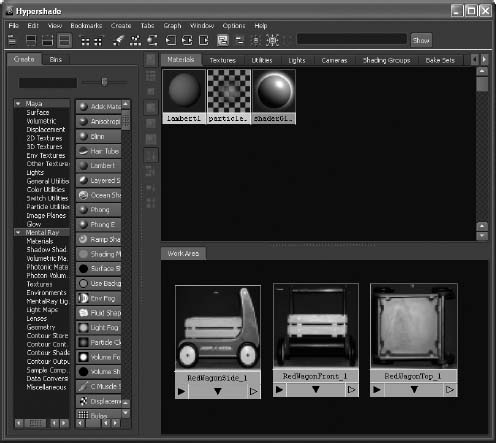
Figure 6.9 Create three new Lambert shaders.
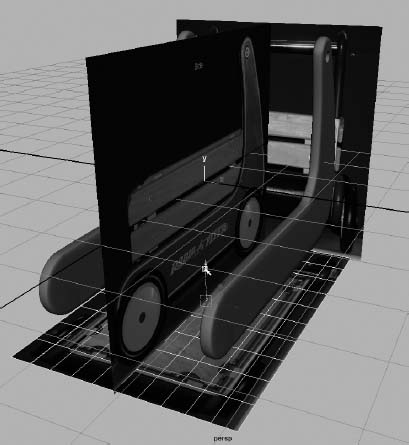
- Assign the shaders to the reference planes. To do so, MMB+drag the Lambert shader that is connected to the side view image to the side view plane in the Perspective panel. Switch the perspective view into Texture mode by pressing 6 while in that panel. You should see the image of the wagon appear, as shown in Figure 6.11.
- Drag the top-view Lambert shader to the top reference plane and the front Lambert shader to the front reference plane to assign the other two views. You should now have the three reference planes laid out as shown in Figure 6.12.
Figure 6.10 Connecting the image to the shader's color
- All isn't rosy yet! The front reference view and the side reference view seem to match up, but the top reference view is off. Select the top reference plane, and rotate it 90 degrees in the Y-axis. Although it's oriented properly now, the top view is larger than the side view plane, and the images still don't line up.
- Scale the top reference plane to match the width of the side view plane, as shown in Figure 6.13.
- Remember that the scale of these planes is small right now. You don't need to use real-world units for this project. However, you should scale the reference planes so that you have a larger scale with which to work. Select all three reference planes, and scale them to about four times their previous size. Don't enter values in the Channel Box; you should scale them by sight. Remember to scale all three reference planes together.
Figure 6.11 The side view photo is mapped to the side view plane.
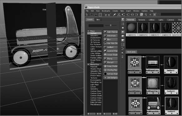
Figure 6.12 All three reference planes are mapped.
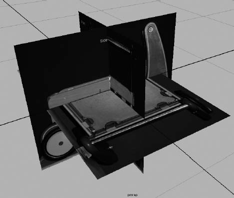
Figure 6.13 Scale the top reference plane to match the side reference plane.

- To give yourself more room to work, select the front view plane and move it back, as shown in Figure 6.14.
Figure 6.14 Scale up the planes together, and then move the front reference plane back.

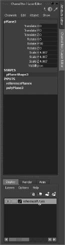
- Create a display layer for the planes to make it easy to manage them later. To do so, in the Layer Editor below the Channel Box, click the Create A New Layer icon (
 ). Double-click the new layer, and name it referencePlanes in the window that pops up (see Figure 6.15). Click Save. Your Layer Editor should resemble the one shown in Figure 6.16.
 - Select all three reference planes, RMB+click the referencePlanes layer, and choose Add Selected Objects from the context menu. For more on the Layer Editor, see “Organizing Workflow with Layer Editor” section in Chapter 3, “The Maya 2012 Interface.” To toggle the display of the reference planes to get them out of the way, simply toggle the box to the extreme left of the layer name. It's currently checked with a V for Visible in Figure 6.16.
Figure 6.15 Name the new layer.
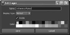
Figure 6.16 The new layer in the Layer Editor
Save your work, and “version up” so you don't write over your previous scene files. You can download the scene file RedWagonModel_v01.ma from the Scenes folder of the RedWagon project from the companion web page to check your work or skip to this point. Just be sure to set your project to the RedWagon project on your hard drive after downloading the entire project from the web page.
To remain in step with this chapter, make sure Interactive Creation is turned off when you create a new primitive.
Modeling the Side Panels
Now that your reference is all set, let's get to work building the model. Here is where the sweat comes in. There are many ways to model the same object, but they all basically stem from the same procedures you've seen in the previous chapters.
Shaping the A Panel
You'll start with the first side piece, marked A in Figure 6.17. Follow these steps:
- Enter the Polygons menu set. Create a default poly cube, and place it in the side view in front of the A piece, as shown in Figure 6.18.
- RMB+click the cube, and select Vertex from the marking menu to enter Vertex Selection mode. Carefully move the corners to place them as shown in Figure 6.19. To place the vertices, use only the Z- and Y-axis handles for the Move tool so that you don't accidentally move the vertices in X as well.

Figure 6.17 You'll build the wagon in this order.
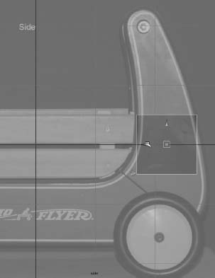
Figure 6.18 Place a poly box for the first side.
You can use the following hotkeys to toggle between menu sets:
F2 Animation F3 Polygons F4 Surfaces F5 Dynamics F6 Rendering Figure 6.20 In the view panels, turn on X-Ray Shading mode. (The side view is shown here.)
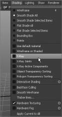
- To be able to see the texture view of the reference planes through the shaded gray cube you just created, you need to enter X-Ray mode. In any of the view panels, click Shading X-Ray, as shown in Figure 6.20.
- This shape obviously won't fit the A panel. You need to add edges to define this mesh better. Choose Edit Mesh Insert Edge Loop Tool. With the Triangular Tool icon, click along the vertical edges to place seven new edge loops, as shown in Figure 6.21. RMB+click the cube, select Vertex to enter Vertex Selection, and move the new vertices to fit the shape of the A panel, also shown in Figure 6.21.
Figure 6.19 Place the four corners of the box to fit the A piece.
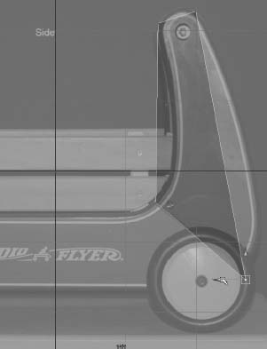
Figure 6.21 Insert edge loops to create more edges and vertices, and then shape the cube to match the A panel as shown here.

- The area around the bend just above the back wheel needs more edge loops to fit the curvature better. Using the Insert Edge Loop tool, insert seven more edge loops as shown in Figure 6.22. In Vertex mode, move the vertices to fit the curvature as shown in Figure 6.23.
- Turn your attention to the top curvature. Using the Insert Edge Loop tool, add four new edge loop divisions to the top of the A panel (see Figure 6.24). Move the vertices to match the curvature, as shown in Figure 6.25.

Figure 6.22 Insert more edge loops.
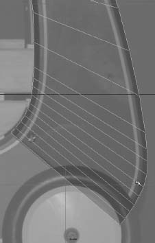
Figure 6.23 Move the new vertices to match the curvature.
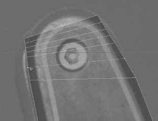
Figure 6.24 Add new edge loop divisions to the top curvature.
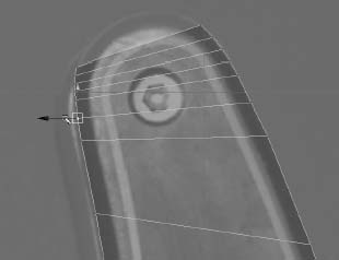
Figure 6.25 Move the new vertices to match the top curvature.
- You need to match the very top curvature by adding vertical edge loops to the mesh. Using the Insert Edge Loop tool, click and drag to add five new vertical edge loop divisions, as shown in Figure 6.26.
- Move the vertices to match the top curvature, as shown in Figure 6.27. Try to place the vertices evenly.
- The mesh for the A panel should look like Figure 6.28. It's too wide and not in place. Using the front view, position the mesh to fit where the A panel goes. Scale the width down to match the width of the panel. See Figure 6.29.
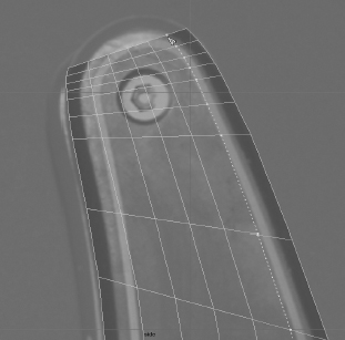
Figure 6.26 Insert five new vertical edge loop divisions.
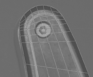
Figure 6.27 Match the curvature of the top.

Figure 6.28 The current state of the mesh
Figure 6.29 Scale and position the mesh in the front view to match the actual A panel.

Fixing Problem Areas
You may notice an awkward polygon face at the top corners of the mesh, as shown in Figure 6.30. This polygon will break apart when you try to round the edges as you can see with the real wagon (Figure 6.17).
Let's add a couple of edges to these faces to circumvent any problems that may arise when you bevel the edges to round them to match the real wagon:
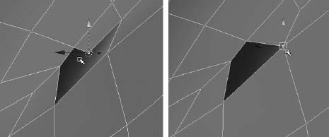
- Choose Edit Mesh Split Polygon Tool, and click and drag to place the first end of the edge at the corner shown in Figure 6.31. Place the other end of the new edge as shown in Figure 6.32.
- Use the Split Polygon tool to place a new edge for the awkward polygon on the reverse side of the A panel, as shown in Figure 6.33.
- Use the Split Polygon tool to place new edges for the awkward polygons on the front and back sides for the right side of the A panel, as shown in Figure 6.34.

Figure 6.30 An awkward polygon corner may cause problems when you round the edges.
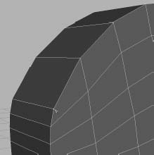
Figure 6.31 Begin the new edge here.
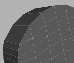

Figure 6.33 Add an edge to the reverse side's awkward polygon face.

Figure 6.34 Add edges to the awkward polygons on the right side (front and back shown; left and right, respectively).
- As you can see in Figure 6.17, the panels on the real wagon are rounded at the edges. You can use Bevel to round the three topside edges of the panel, leaving the bottom rim of the panel flat for now. In the Polygons menu set, choose Select Select Edge Loop Tool. Double-click one of the edges to select the entire edge loop for the front of the panel. Double-click one of the edges to select the loop of edges on the back side of the panel, as shown in Figure 6.35. Notice that the bottom loop of edges isn't selected; this is fortunate for you in this case. You can always select each of those edges individually; however, the Select Edge Loop tool makes it quite a bit easier.
Figure 6.35 Select the edge loops for the front and back.
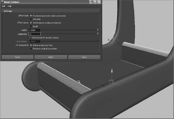
- With those edge loops selected, choose Edit Mesh Bevel to open the option box for the Bevel command. Set Width to 1.0 and Segments to 2, as shown in Figure 6.36. Click Bevel to create the beveled edge shown in Figure 6.37. It's not quite as round as it should be, but you'll tackle that with a Smooth operation in the following steps.
Figure 6.36 Settings for the Bevel operation

Smoothing the Panel
Next, you'll smooth the panel for a better fit to the real panel and a nicer look overall. Because the panel isn't as rounded as you'd like, you'll want to add a Smooth to the mesh, as you did in Chapter 4, “Beginning Polygonal Modeling,” with the hand model. With the panel mesh selected, press 3 to display the panel as it will look after it's smoothed. Notice that the panel looks subtly but appreciably better with the Smooth preview. However, the bottom of the panel becomes too smooth, as you can see in Figure 6.38. To fix this, you'll add divisions to the bottom in the next step:
- Press 1 to return to the normal view of the mesh.
- Use the Insert Edge Loop tool to insert three new edge loops at the bottom of the panel, as shown in Figure 6.39. Toggle between previews 1 and 3 to see how much better the smoothing will look at the bottom.

Figure 6.37 The rounded edges after the Bevel

Figure 6.38 In the preview, the bottom of the A panel becomes too smooth when you press 3.
Figure 6.39 Insert three new edge loops at the bottom of the panel.

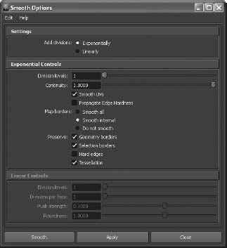
- Now for the Smooth operation. Select the panel, and make sure you're back in normal mesh view by pressing 1. Choose Mesh Smooth . In the option box, make sure Exponentially is selected and Division Levels is set to 1 (the default settings), as shown in Figure 6.40. Click Smooth. The A panel should look much nicer. Check it against the reference planes, and it should fit better.
Figure 6.40 The Smooth options
- Look in the Channel Box to see the history of all the work you did on the project (see Figure 6.41). Let's work cleanly and get rid of this history. With the mesh still selected, choose Edit Delete By Type History.
To keep track of your progress, you can save the file of your wagon scene manually and rename it with new version numbers, or you can use Incremental Save to let Maya make backups for you. (Make sure the option is turned on through File
Save Scene .) - Select the mesh, and name it Apanel in the Attribute Editor or Channel Box. Your finished panel shape is shown in Figure 6.42. While you're at it, name the reference planes as well: sideRef, topRef, and frontRef.
Save your work, and version it up so you don't write over your previous scene files. You can download the scene file RedWagonModel_v02.ma from the Scenes folder of the RedWagon project from the companion web page to check your work or to skip to this point.
Using Booleans
Now that you've worked out the shape of the A panel and the model is clean and named, you'll use a Boolean operation to cut a hole in the top of the panel for the handlebar that crosses between the panels (see Figure 6.43).
Booleans are very impressive operations that allow you to, among other things, cut holes in a mesh fairly easily. Basically, a Boolean is a geometric operation that creates a shape from the addition of two shapes together (Union), the subtraction of one shape from another (Difference), or the common intersection of two shapes (Intersection).
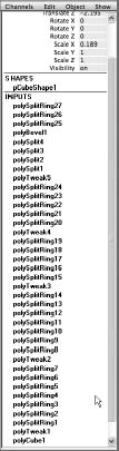

Figure 6.42 The finished panel shape
Be forewarned, however, that Boolean operations can be problematic. Sometimes you get a result that is wrong—or, even worse, the entire mesh disappears and you have to undo. Use Booleans sparingly and only on a mesh that is clean and prepared. You've cleaned and prepped your panel mesh, so there should be no problems. (Actually, there will be a problem—but that's half the fun of learning, so let's get on with it.)
Creating the Boolean Object
For the red wagon, you need to cut a hole into the panel to bolt in the handlebar, as you can see in Figure 6.43. In this case, you'll use a Difference Boolean. You need to cut a cylindrical hole out of the mesh at the location of the handlebar (refer to the side reference plane in the Side view panel). For a Boolean, you need two meshes. The panel is the first mesh to be affected, and the second mesh will be a polygonal cylinder to represent the handlebar.

Make sure Interactive Creation is turned off, and follow these steps:
- In your scene, create a polygonal cylinder with Axis Divisions of 24 and Height Divisions of 2 (choose Create Polygon Primitives Cylinder ), as shown in the Polygon Cylinder option box in Figure 6.44.
Figure 6.44 Polygon Cylinder Options

- Using the side view as reference, scale, orient, and place the cylinder to match up with the handlebar. Scale the cylinder to go all the way through the panel mesh, as shown in Figure 6.45. Try to center the cylinder's middle at the center line of the width of the mesh.
Figure 6.45 Place the handlebar cylinder.

- First select the panel mesh, and then select the handlebar cylinder. Choose Mesh Booleans Difference. The cylinder disappears, and the panel mesh now has a hole cut through it, as shown in Figure 6.46.
Figure 6.46 The Boolean cuts a hole in the mesh.

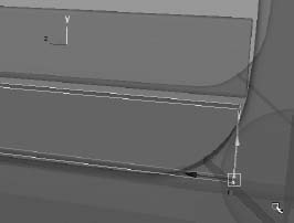
- But now you have a problem! It's not easily seen, but there is a tear in the mesh, close to the rounded edge. Figure 6.47 shows the location of the tear, and Figure 6.48 shows a closer rendered view of the tear. It goes all the way through. If you don't see a tear in your mesh, you can skip the next section, “Fixing Tears,” if you wish.
Figure 6.47 There is a tear between the faces.
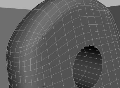
Figure 6.48 A render of the mesh shows the tear on both sides of the mesh panel.

Fixing Tears
Remember when I said Booleans can be problematic? Here is a perfect example. You'll work on fixing the tear by first moving and merging vertices. Let's begin on the front side of the mesh. You'll have to repeat these steps for the tear on the back side of the mesh:
- Select the entire mesh object, and delete its history (Edit Delete By Type History).
- Select the vertex shown on the left in Figure 6.49, and snap it (with Point Snap) to the vertex just above it, shown on the right.
Figure 6.49 Select and snap the vertex to begin cleaning the tear.

- Select both those vertices to merge them. Choose Edit Mesh Merge. The vertices don't become one, as you saw in an earlier exercise in Chapter 4.
- Select the vertex shown on the left in Figure 6.50, and snap it onto the vertex just below it, as shown on the right.
Figure 6.50 Select and snap the second vertex to clean the tear.
- Select both vertices, and merge them as in step 3. Now you have a clean hole in the front of your panel's mesh that can be filled with a simple four-sided polygon face.
- Use the same procedures in steps 2 through 5 to clean the tear in the back of the panel's mesh, as shown in Figure 6.51.
- You now should have two simple four-sided holes in your mesh, front and back. Select the entire mesh, and choose Mesh Fill Hole. Bam! Maya fills in both tears in the front and back of the panel mesh with a simple four-sided polygonal face. Figure 6.52 shows the newly formed face on the front side of the mesh.
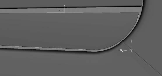
- There is a little scar from the tear that you can probably see in the Shaded mode of the mesh (see Figure 6.53). This scar won't show up in your renders after you texture and shade the wagon in the next chapter. Otherwise, your fix works great. Select the mesh, and delete its history. Rename the mesh back to Apanel, because the Boolean operation changed the mesh's name to polySurface1.
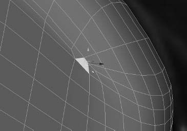
Figure 6.51 To clean up the tear, snap the vertices on the back side of the panel's mesh.
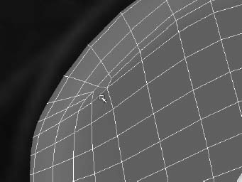
Figure 6.52 The tears are filled in with new faces.
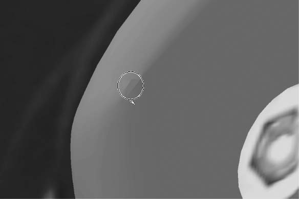
Figure 6.53 The fix works great. It leaves a little scar that won't show in your renders later in the book.
Cleaning the Faces Around the Handlebar Hole
With the tears fixed, turn your attention to the faces that surround the hole you cut for the handlebar. Although there are no longer any glaring issues evident, several faces that border the hole have more than four sides. This isn't always an immediate problem, but rendering and modeling issues may crop up further down the road of you don't clean up these faces:
- Select the faces that surround the handlebar hole one by one for the front side of the mesh. Then, while holding down the Shift key, select the faces around the hole on the back side of the mesh. Don't select the faces that make up the inside tunnel of the hole. See Figure 6.54.
Figure 6.54 Select the faces that border the hole.

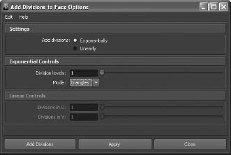
- With the faces selected, choose Edit Mesh Add Divisions r, and set the options as shown in Figure 6.55.
Figure 6.55 The Add Divisions settings
- The faces around the hole fill in with new divisions that match the way the hole is segmented and cut. See Figure 6.56.
- Select the mesh, and delete its history.
Figure 6.57 shows the final A panel in perspective view. Save your work! You can download the scene file RedWagonModel_v03.ma from the Scenes folder of the RedWagon project from the companion web page to check your work or to skip to this point.
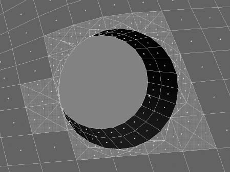
Figure 6.56 Add Divisions cleans up the faces by aligning the segments with new edges and faces.
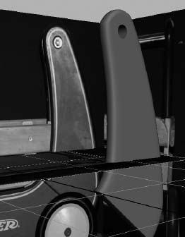
Figure 6.57 Final A panel in perspective view
Shaping the B Panel
Now that everything is nice and clean and your A panel mesh is finished, you're ready to move on to the B panel (shown earlier in Figure 6.17):
- Create a new polygon cube, and place it in the side view to line up with the B panel. Move the corner vertices in the side view to roughly line up, as shown in Figure 6.58.
Figure 6.58 Set up the new polygonal cube to fit roughly over the B panel.
- You need to add edge loops as you did with the A panel to match the curvatures of the B panel in the real wagon. Add six edge loops as shown in Figure 6.59 for the right side of the panel.
Figure 6.59 Add edge loop divisions.
- Move the vertices to match the curvature of the B panel, as shown in Figure 6.60.
Figure 6.60 Move the new vertices to match the curvature of the B panel.
- Select the B panel mesh, and scale and position it in the front view to line up with the B panel of the real wagon in the front reference plane, as shown in Figure 6.61.
Figure 6.61 Line up the position and size of the panel.
- To make the curvature of the B panel at the front of the wagon, use the Wedge procedure you used in the hand exercise in Chapter 4. First, look at the end face of the B panel. You need to split that into two faces for a proper Wedge.
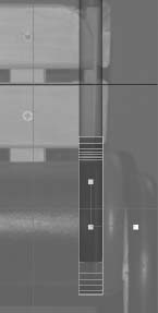
- Select Edit Mesh Split Polygon Tool. Click and drag a point on one edge of that end face to put it at exactly 50 percent, as shown to the left in Figure 6.62. Release the mouse button to place the point, and then click and drag the opposite edge to place the other point for the new edge also at 50 percent, as shown on the right in Figure 6.62. Notice that the readout in the very bottom-left corner of the UI shows the percentage as you drag the point on either edge, also shown in the bottom-left corner of both sides in Figure 6.62.
Figure 6.62 Split the end face in half to prep for the Wedge.

- Right-click the mesh, and choose Face from the marking menu to enter Face Selection. Select the top face of the newly split end. Then, RMB+click the mesh, and select Edge to enter Edge Selection mode. With the Shift key depressed, Shift+select that new middle edge, as shown in Figure 6.63.
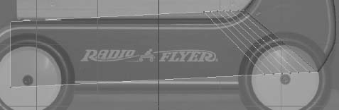
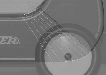
- Choose Edit Mesh Wedge Face . Set Arc Angle to 180 and Divisions to 10. Click Wedge Face, and the end of the B panel is rounded at the end. See Figure 6.64.
- In the side view, select all the vertices at the end and position the arc to match the curvature of the wagon's real B panel. See Figure 6.65.
Figure 6.63 Select the top face as well as its bottom edge.
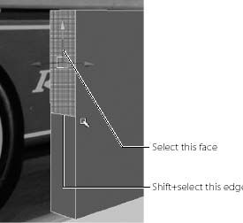
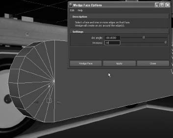
Figure 6.64 Wedge the face at the end to create the curvature of the panel.
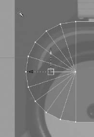
Figure 6.65 Move the vertices as a whole to fit the end curvature to the real curve of the wagon's panel.
Rounding the Edges
Now, you'll round the edges of the B panel in these continuing steps:
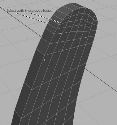
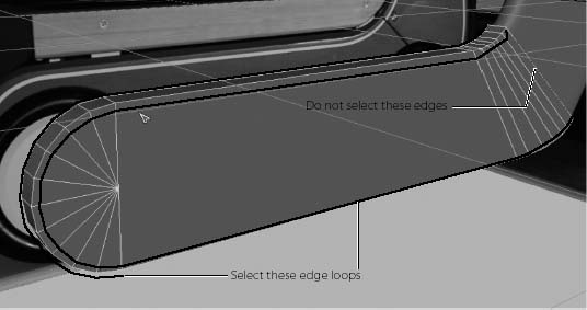
- Using the Select Edge Loop tool (Select Select Edge Loop Tool), select the edges that run along the B panel mesh. Don't select the edges where the B panel meets the A panel. See Figure 6.66.
Figure 6.66 Select these edge loops that run along both edges of the panel.
- Choose Edit Mesh Bevel , and set Width to 0.5 and Segments to 2 as shown. Click Bevel, and your B panel edges will be rounded as shown in Figure 6.67.
Figure 6.67 Bevel to round the edges of the B panel.

- With the mesh selected, toggle in and out of smooth mesh preview using the 1 and 3 keys to see how the mesh would look after being smoothed. You'll have issues with the end that meets the A panel, so you'll have to insert edge loop divisions at that end to prevent the model from becoming too smooth. Using the Insert Edge Loop tool, insert three new edge loops at the very end of the B panel where it meets the A panel, as shown in Figure 6.68.
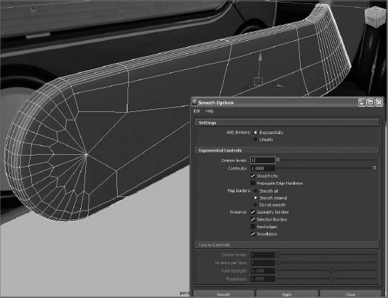
- Select the B panel mesh, and choose Mesh Smooth . Set Add Divisions to Exponentially and Division Levels to 1. Click Smooth, and your B panel is done! See Figure 6.69.
- Select the mesh, name it Bpanel, and delete its history.
Figure 6.68 Insert edge loops to prevent this end from smoothing too much.
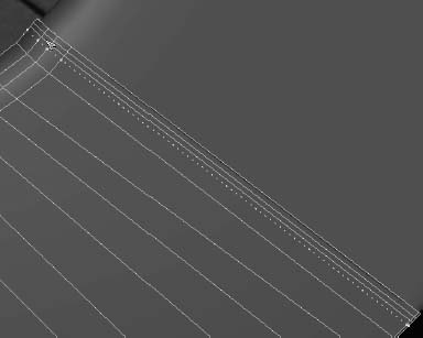
Figure 6.69 Smooth the B panel mesh.
Cleaning Up the Scene
Now, let's put these objects into a good hierarchy and clean everything up. Select both the A and B panels, and freeze their transforms: choose Modify ![]() Freeze Transformations. This resets the values for the mesh's position and the rotation to 0 in all axes and sets the scale values back to 1. It doesn't adjust the objects in the slightest; it only resets their values back to an original value to keep things nice and clean. After you froze the transformations, the meshes stayed in place, but their values in the Channel Box reverted back to 0s (Translate and Rotate) and 1 (Scale).
Freeze Transformations. This resets the values for the mesh's position and the rotation to 0 in all axes and sets the scale values back to 1. It doesn't adjust the objects in the slightest; it only resets their values back to an original value to keep things nice and clean. After you froze the transformations, the meshes stayed in place, but their values in the Channel Box reverted back to 0s (Translate and Rotate) and 1 (Scale).
Freeze Transformations (also referred to as freezing transforms) sets the values of the object's settings back to their defaults (that is, it sets Translate and Rotate back to 0 and Scale back to 1). It doesn't reset the size or positions—just the number values in the attributes. This is useful for getting an object back to default conditions without losing all the work done to it. Using Freeze Transformations keeps things clean as you work, and doing so is usually a good idea when you're working with patches.
With both the panels still selected, group them together by choosing Edit ![]() Group or by pressing Ctrl+G. Name the new group rightSidePanels.
Group or by pressing Ctrl+G. Name the new group rightSidePanels.
With the rightSidePanels top node selected, duplicate the panels by pressing Ctrl+D or by choosing Edit ![]() Duplicate. Move them in the front view to line up with the left side of the wagon, as shown in Figure 6.70. Name the duplicated group leftSidePanels. Notice that the panels don't line up perfectly to the reference images. This is due to the perspective in the photos and is to be expected. Use the upper part of the panels to line everything up, as shown in Figure 6.70.
Duplicate. Move them in the front view to line up with the left side of the wagon, as shown in Figure 6.70. Name the duplicated group leftSidePanels. Notice that the panels don't line up perfectly to the reference images. This is due to the perspective in the photos and is to be expected. Use the upper part of the panels to line everything up, as shown in Figure 6.70.
Figure 6.70 Duplicate and position the panels to the other side of the wagon.
Save your work to another version number. You may want to download the scene file RedWagonModel_v04.ma from the Scenes folder of the RedWagon project from the companion web page to check your work or to skip to this point.
Creating the Wagon Body
Now that you've finished the hardest part of the process, you can concentrate on getting the body of the wagon built between the two side panels (called out as C in Figure 6.17 earlier in the chapter).
Look in the top view, and you probably won't see all the side panels. This is because the top reference plane is blocking it. Select the top reference plane, and move it down as shown in Figure 6.71 to give you a little more room in which to work.
Figure 6.71 Move the top reference plane down a bit.
Creating the Floor
To begin the floor of the wagon, follow these steps:
- In the top view, create a polygonal cube. Scale and position it to fit the bottom of the wagon body using all the views as reference, as shown in Figure 6.72.
- Using the Insert Edge Loop tool, insert edge loops at the ends of the wagon's floor at about the same thickness as the side panels, as shown in Figure 6.73.
- Select both the new faces created on top of the floor. Choose Edit Mesh Extrude to pull up the ends to just under the lip of the panels to make a box, as shown in Figure 6.74.

Figure 6.72 Place and scale the box to be the bottom of the wagon body.

Figure 6.73 Insert Edge Loop divisions at both ends of the floor.
Figure 6.74 Extrude the top faces to make an open-faced box.
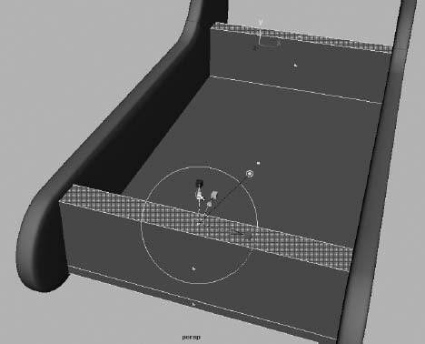
- You need to round the new edges of the box to match the panels. Select the edges of the front and back box ends, as shown in Figure 6.75.
Figure 6.75 Select these edges.
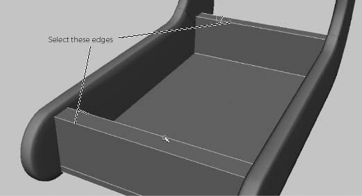
- Choose Edit Mesh Bevel . Set Width to 1.0 and Segments to 12. Click Bevel, and your edges are rounded beautifully, as shown in Figure 6.76. Name the cube wagonFloor.
Figure 6.76 Bevel does a great job of rounding these edges.
Creating the Bullnose
Next, let's create the bullnose in front of the wagon body (part D, called out earlier in Figure 6.17), as shown in Figure 6.77.
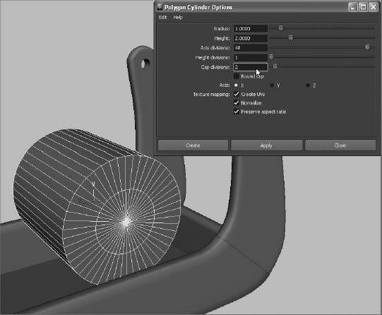
- Create a polygonal cylinder with the options shown in Figure 6.78. Set Radius to 1, Height to 2, Axis Divisions to 48, Height Divisions set to 1, Cap Divisions to 2, and Axis to X.
- You only need the front half of the cylinder. In the top view, select the cylinder, and choose Edit Mesh Cut Faces Tool . In the options box, set Cut Direction to XY plane, and select the Delete Cut Faces check box. Click Cut, and half of the cylinder immediately deletes at the center line, as shown in Figure 6.79. You could use the Special Manipulator to move the cut plane back and forth to cut the cylinder at a different place; but because it's already at the center, you're fine.
- Press W to enter the Move tool and exit the Cut Faces tool. Move and scale the cylinder to fit into the front of the wagon, as shown in Figure 6.80. Name the cylinder bullnose. The bullnose is ready!
- Select both the wagonFloor and bullnose objects, and delete their histories.
Figure 6.78 Create a poly cylinder with these settings.
Save your work to a higher version number. You may want to download the scene file RedWagonModel_v05.ma from the Scenes folder of the RedWagon project from the companion web page to check your work or to skip to this point.
The wagon's body is finished. You can insert the handlebar into the side panels.
Figure 6.79 Cut the cylinder in half.

Figure 6.80 The bullnose is in place.

Inserting the Handlebar
The handlebar is a pretty easy affair to create. It's a simple cylinder that fits in the holes at the top of the side panels. However, each end has a bolt that holds the bar in place. Although you don't have to be completely accurate and create a washer and bolt, it's nice to add the detail of a bolt at either end of the handlebar.
Making the Handlebar
To begin the handlebar, follow along here:
- Create a poly cylinder with Axis Divisions of 24, Height Divisions of 2, and Cap Divisions of 1.
- Scale, rotate, and position the cylinder to fit between the side panels, fitting into the holes. For the best effect, make sure the cylinder is a little smaller than the holes. Figure 6.81 shows the handlebar in place.
Figure 6.81 Place the cylinder.

- Make sure the ends of the handlebar are about halfway through the holes to make room for the bolts. Name the cylinder handlebar.
Making the Bolts
Now, you'll make a bolt for the handlebar in these steps:
- Create a poly cylinder with the following options: Axis Divisions = 6, Height Divisions = 1, Cap Divisions = 2, and Axis = X. (See Figure 6.82.)
- Select the inner faces of the cap facing forward, as shown in Figure 6.83, and move them back into the cylinder to create a depression.
- Select the back vertices of the cylinder, and move them closer to the front to shorten the cylinder, as shown in Figure 6.84. It's still a rather large bolt, but don't worry about that yet.
- Create another cylinder, this time with Axis Divisions set to 16 and Cap Divisions set to 1. Scale and orient the new cylinder to fit through the bolt head slightly, as shown in Figure 6.85.
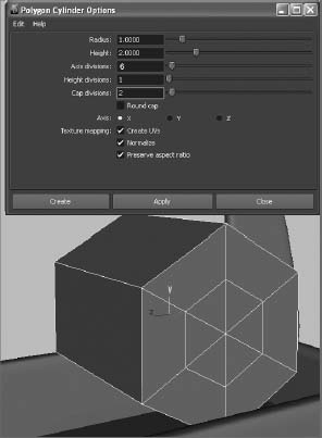
Figure 6.82 Starting the bolt model.
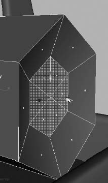
Figure 6.83 Create an indent in the cap of the bolt head.
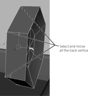
Figure 6.84 Shorten the bolt cylinder.

Figure 6.85 Place a cylinder slightly through the bolt head.
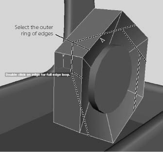
- Let's make the bolt head a lot nicer. Using the Select Edge Loop tool, select the outer loop of edges all the way around the bolt head, as shown in Figure 6.86.
Figure 6.86 Select the outer loop of edges.
- Bevel the outer loop of edges with a Width setting of 0.3 and a Segments value of 3, as shown in Figure 6.87.
- Select the outer loop of edges for the inner cylinder, and bevel them with the same settings. Figure 6.88 shows the result.
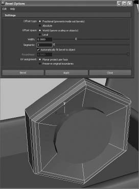
Figure 6.87 Bevel the end of the bolt head.
- Select the bolt head object, and name it boltHead. Select the inner cylinder for the bolt, and name it boltBody.
- Select both the boltBody and boltHead objects and group them together (Ctrl+G). Name the new group bolt.
- Scale the bolt group down to a good size, and place it inside the hole in the side panel up against the handlebar's end, as shown in Figure 6.89.
Figure 6.89 Size and position the bolt.

- With the bolt group in place and still selected, freeze its transforms by choosing Modify Freeze Transformations.
- To make another bolt for the other side of the handlebar, simply duplicate the bolt group by pressing Ctrl+D. Then, with the duplicate group (bolt1) selected, enter a scale of −1.0 in the ScaleX value in the Channel Box. (See Figure 6.90.)
Figure 6.90 Place the duplicated bolt on the other end of the handlebar.

Figure 6.91 shows the progress of the wagon so far. With the body of the wagon pretty much finished, you can move on to the wheels.

Modeling the Wheels
What's a kid's wagon without wheels? That would be no fun. How else would it smash into all your expensive stuff? You're going to make a wheel for the wagon and then duplicate it. Figure 6.92 shows the object of your design. You'll complete the wheel model by revolving a NURBS surface and converting it to a poly.
Figure 6.92 Ensign, take the wheel! (The author is a dork.)

Creating the Profile Curve
You'll begin the first wheel by creating a profile curve to match the cross-section of the wheel on the wagon. This is where coloring between the lines in kindergarten comes into play. You did color inside the lines, right?
- Select Create CV Curve Tool. In the top view, lay down the first CV on the grid. As you'll notice, the first CV is displayed as a closed box. Lay down the second CV a little lower in the Z-axis, and you see the second CV displayed as an open-sided box. This display shows you the direction of a curve. Lay down a third CV to the right of the second CV in the X-axis, as you see in the upper-right CVs shown in Figure 6.93.
It's important to create the curve in the top view.
No curve is displayed between the three CVs. A NURBS curve based on CVs will begin to appear after you've laid down the fourth and all subsequent CVs.
- To match the profile shape, continue laying down the rest of the CVs counterclockwise to the curve, as shown in Figure 6.93.
- After you lay down the last CV at the upper-left corner, press Enter to complete the curve. The CV display turns off, and you have a bare curve.
- You can adjust the curve by entering Component mode and moving the CVs to taste. Make sure the first and last CVs line up. Use the grid to help you. The final profile shape is essentially a big U with a small notch cut out of the lower-right side where the tire meets the rim. Check the size of the profile curve, and make sure it's about the size of half the wheel in the top reference image in the top view. This profile curve will be revolved around an axis and will fill in a surface for the entire wheel. You can always scale the finished wheel later, so getting this step perfect isn't critical.
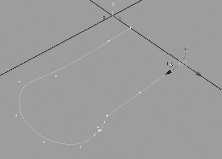
- As you can see in Figure 6.94, the pivot point of the curve is at the origin, no matter where on the top grid you drew the curve. You need to move the pivot to the first CV of the curve. First, to display the CVs of the curve without entering Component mode, select the curve and choose Display NURBS CVs.
- Press W to activate the Move tool, and then press Insert (Home on a Mac system or fn+Home/Left Arrow key on a MacBook Pro) to enter Pivot mode, as you did in the Solar System exercise earlier in the book. Hold down the V key to enable Snap To Points, and snap the pivot to the first CV of the curve (the upper-right corner of the curve), as shown in Figure 6.95.

Figure 6.93 Match this profile shape with a CV curve in the top view.
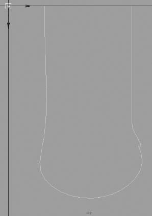
Figure 6.94 The pivot point for the profile curve you just created is at the origin.
Figure 6.95 Place the pivot at the beginning CV of the curve.
Creating the Revolved Surfaces
Now you can revolve the profile curve to make the base shape of the wheel as you continue by following these steps:
- Select the curve, and move it to the origin; now its first CV lies on the origin. Turn off CV display by selecting Display NURBS CVs.
WHEEL TESSELLATION
What are all those numbers you input for the revolve surface? Because you're generating the wheel surface as a polygon mesh using a NURBS surfacing technique, you have to tell Maya the proper parameters for the poly surface. If the tessellation values, which are determined by the Tessellation method and the attribute values below it (as shown in Figure 6.96) aren't just right, the wheel's mesh will be revolved without all the details you need. These settings seem to be the best tessellation for the wheel through trial and error by creating the wheel, changing the tessellation values interactively, and seeing the results update through surface history.
As a test (save your scene first!), select the newly revolved wheel mesh before you delete history on it. In the Attribute Editor, you'll see a tab for the recently created mesh called something like nurbsTessellate1. Click that tab to open its attributes, and change some of the values under the Advanced Tessellation Options
Standard Fit Options heading. Because history is still attached to this mesh, it changes the mesh interactively as you change the tessellation options. After you've had your fill, revert back to your saved file, and continue with the exercise. - Enter into the Surfaces menu set, select the curve, and choose Surfaces Revolve . In the option box, set the options as shown in Figure 6.96. Click Revolve and your wheel appears, as shown in Figure 6.97. For more on tessellation settings, see the “Wheel Tessellation” sidebar before you move on to the next steps and before you delete the surface history on the wheel mesh.
- Move the pivot point of the wheel to the center of the rim. Name the surface wheelMesh.
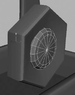
- You need to add the little nub of the wheel at the rim, as you can see in the photos back in Figure 6.92. Just as you did with the wheel's profile curve, create a profile curve for the little inset cap. As best you can, match the shape and position to the one shown in Figure 6.98. This time, start the curve on the lower-left of the curve shown, and work your way counterclockwise up to the upper-right corner, ending the curve at the same height as the wheel at the X-axis.
- Move the pivot point of the new profile curve to its last CV, as shown in Figure 6.99. Put the curve at the origin; its last CV should now rest at the origin.

Figure 6.96 Revolve options for the wheel
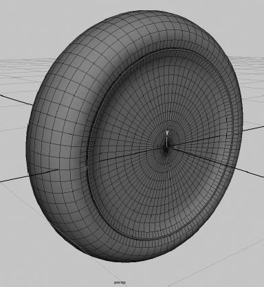
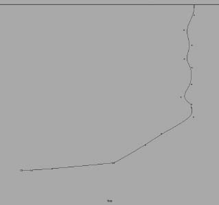
Figure 6.98 Create a new profile curve for the hubcap detail.

- Select the new profile curve, and revolve a new surface using the same settings as before in Figure 6.96 (see Figure 6.100).
- Select and move the new cap mesh into the middle of the wheel's rim, and size the cap to fit using the side view reference. Name the object capMesh. See Figure 6.101.

Figure 6.100 The hubcap detail surface
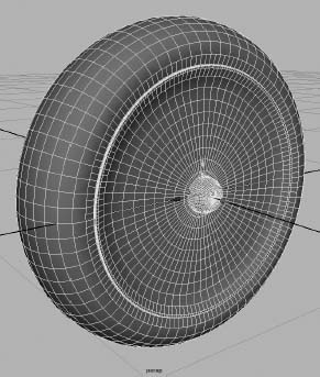
Figure 6.101 The wheel is complete!
- If you want to adjust the shape of the wheel or the hubcap nub, you can adjust the CVs on your profile curves; the surfaces will adjust, provided history is still intact. Delete both the profile curves for the wheel and the cap, if you haven't already. Doing so also deletes the history on the surfaces, which is fine after you're pleased with the shape of both surfaces.
- Select both the wheel and the cap meshes, and group them together by pressing Ctrl+G. Name the group node wheel.
- With the wheel node selected, center the pivot by choosing Modify Center Pivot. Doing so places the pivot for the wheel assembly properly in the center of the wheel.
- Using the side view reference, position the wheel to the back of the wagon using the top wheel node to place it, as shown in Figure 6.102. If you need to, scale the wheel's top node to fit it to the real wheel using both the side and front reference planes for sizing.
Figure 6.102 Place the first wheel.
- Duplicate the wheel, and place it on the other side of the wagon's back end. Select the top node (wheel1), and scale it in the X-axis to −1.0 to mirror it properly.
- Duplicate both the rear wheels and place them at the front of the wagon, as shown in Figure 6.103. Don't worry about placing the wheels exactly where they're shown in the front reference plane; use the side view for positioning. Due to the perspective of the photo, they won't line up accurately in both reference planes, so it's best to keep all the wheels lined up in the Maya scene, as you can see in Figure 6.103.
- After you've placed the wheels, freeze their transforms: select the four top wheel nodes, and choose Modify Freeze Transformations. Doing so sets the transform values for the wheel nodes to 0 in translation and rotation and 1 in scale without altering them in any way.
Because the axles of the wheels aren't very noticeable, there is no need to build them. Simply placing the wheels close to the body in the correct positions will suffice. Now you have a wagon that can roll—and, if you have a kid, you know it'll end up rolling over your toes pretty soon. The red wagon is starting to take shape. Enjoy a frosty beverage—perhaps a smoothie—save your work, and get ready to finish this wagon in the next sections.
You may want to download the scene file RedWagonModel_v06.ma from the Scenes folder of the RedWagon project from the companion web page to check your work or to skip to this point. You'll move on to the wooden railings in the next section.
Figure 6.103 Duplicate and place the other three wheels.

Making the Wood Railings
Remember Figure 6.17? Take a peek at that figure again; I'll wait. You'll see that all that remains to do for your model are the wood railings placed around the four sides of the wagon.
These models will be pretty simple; they're all based on poly cubes with some slight alterations to round a corner here or there. To start modeling the rails, begin with these steps:
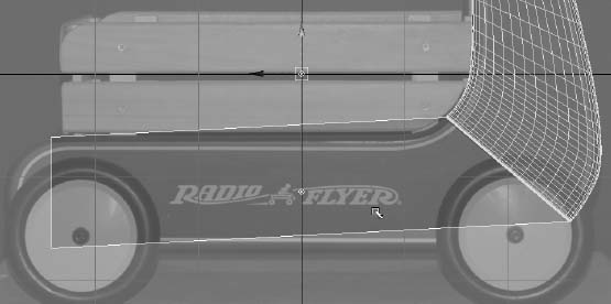
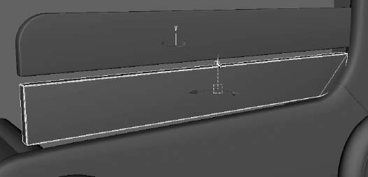
- Switch back to the Polygons menu set. In the Side view panel, create a poly cube; use the side and front reference planes to scale and place the cube to fit the top rail on the side, as shown in Figure 6.104. Again, use the side reference view primarily to position the railing, because the front and top view will be a little off due to perspective in the photos.
- To round the one corner of the railing, select the top edge at the end to be rounded and choose Edit Mesh Bevel . Reset your Bevel settings by selecting Edit Reset Settings in the option box. Set Segments to 12, and bevel that edge, as shown in Figure 6.105.
Figure 6.104 Create a cube, and position it to be the top rail on the side of the wagon.

Figure 6.105 Bevel the end of the rail.

- It's unseemly to leave the rest of the edges of the mesh sharp. Adding a slight bevel to the edges will enhance the look and fidelity of the railings in your model. Especially when you begin lighting, beveled edges and corners are much nicer than perfectly sharp edges and corners, even if it's a small bevel. Select the outer edges that run all the way around the cube, as shown in Figure 6.106.
- Set the Bevel options to a Width value of 0.25 and a Segments value of 3, and bevel those outer edges, as shown in Figure 6.107.
Figure 6.106 Select the outer edges but not the inner edges.
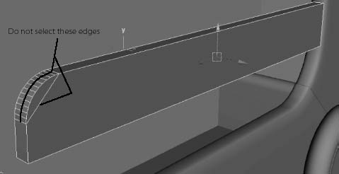
Figure 6.107 Put a slight bevel around the railing.

- Delete the history from the top railing, and freeze its transforms (Modify Freeze Transformations).
- Create another cube. Scale and position it as the bottom rail under the one you just created. See Figure 6.108.
- You need to bevel the end of the bottom railing to match the real railing on the wagon. But the cube is resting inside the wagon mesh right now, because you already lined it up perfectly. The easiest thing to do here is to freeze transforms on the cube so its position values reset to 0,0,0 in X, Y, Z space.
- Move the cube out of the way of the wagon, anywhere in the scene you'd like. I suggest you move it just above the wagon so you can see the obscured end more easily, as shown in Figure 6.109.
- Select the bottom edge at the right end of the cube, as shown in Figure 6.110.
- Set your Bevel options to Width 1.0 and Segments 12, and bevel that end, as shown in Figure 6.111.
- While the object is still clear of the wagon, bevel the outside edges as you did on the other railing. Select all the outer edges, being careful not to select the inner edges, and bevel them with Width 0.25 and Segments 3, as before. See Figure 6.112.
Figure 6.108 Place a second cube for the bottom railing.
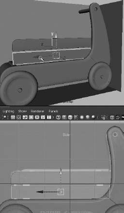
Figure 6.109 After you freeze transformations, move the cube to a better space in which to work.

Figure 6.110 Select the bottom edge on the right end of the cube to round that end.
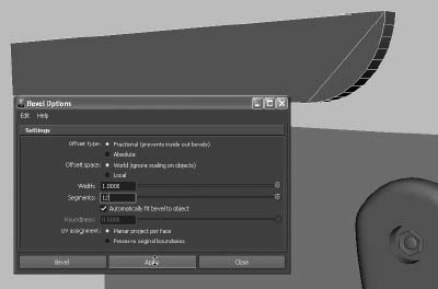
Figure 6.111 Bevel the end to round it out.
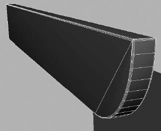
Figure 6.112 Bevel the rest of the edges.
- What good is the railing if it's nowhere near the wagon? That's easy to fix. Earlier, you froze its transforms so that, in its proper place, the railing was at location (0,0,0) in 3D space. Therefore, you can enter those values in the Channel Box to place the railing exactly where it was before. Figure 6.113 shows the bottom railing back in place; however, it's still cutting into the wagon. You'll fix it in place with a lattice.
Figure 6.113 Put the railing back.
- With the bottom railing still selected, switch to the Animation menu set (F2), and choose Create Deformers Lattice . Set Divisions to 2, 2, 2, and click Create.
- Enter X-Ray mode in the Perspective panel (choose Shading X-Ray in the persp panel's menu bar). You see the lattice sticking into the wagon body, as shown in Figure 6.114.
Figure 6.114 Create a lattice.

- With the lattice still selected, RMB+click one of the lines of the lattice, and select Lattice Point from the marking menu. You may have to RMB+click around to get the correct marking menu that displays Lattice Point as a selection option. Try not to RMB+click the wagon itself, to avoid having the wrong marking menu appear. Select the two bottom lattice points, as shown in Figure 6.115.
Figure 6.115 In X-Ray mode, select the bottom lattice points on the end buried in the wagon.
- Exit X-Ray mode with the lattice points still selected by choosing Shading X-Ray to toggle it off in the persp panel. Move the two lattice points to deform the bottom rail's end properly to create a gap between the railing and the wagon, as shown in Figure 6.116.
Figure 6.116 Use the lattice to put a gap between the curved railing and the wagon.
- Select the railing mesh object, and delete its history to remove the lattice but keep the deformation. Switch back to the Polygons menu set (F3).
- You need to make the braces behind the railings. Create a poly cube, and then scale and position it to match the front end brace behind the railings, as shown in Figure 6.117. The brace should reach the floor of the wagon and should extend to just below the top railing edge.
- With the cube selected and in position, choose Edit Mesh Bevel . Set Width to 0.25 and Segments to 3. This puts a slight bevel around the entire edge of the brace, as shown in Figure 6.118. Having edges beveled helps light catch the edges of an object when you light and render it, even for seemingly inconsequential parts of the model.
- Duplicate the brace, and place it toward the back of the wagon according to the side reference image. See Figure 6.119.
- Select the top rail, and name it topRail. Name the bottom rail bottomRail, and name the braces brace1 and brace2. Select all four objects (two rails and two braces), and group them together. Name the group sideRailing. Center the pivot (Modify Center Pivot).
- With the sideRailing group selected, duplicate the group and move it to the other side of the wagon. Set its X scale to −1.0 to mirror it. Place it properly against the other side of the wagon, as shown in Figure 6.120. Feel free to adjust the length of the side railings to make them fit your model best; they don't need to line up exactly to the side reference image plane. Do what looks best for your model if you find you're deviating a bit from the reference images—which is easy to do.
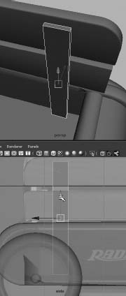
Figure 6.117 Place a cube as the brace behind the railings.

Figure 6.118 Bevel the brace.

Figure 6.119 Duplicate and place the second brace.
Figure 6.120 Duplicate, mirror, and place the other side's railing.
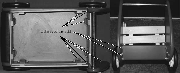
- Use the same procedures as in the previous steps to create the front and back railings. Figure 6.121 shows these railings in a more detailed photo. The front railing is shown on the left, and the back railing is shown on the right.
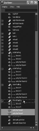
- After you've created the railings, be sure to name them properly. Group the front railing objects together, and name the group frontRailing. Group the objects for the rear railing together, and name that group rearRailing. Figure 6.122 shows the railings in place, and Figure 6.123 shows the Outliner view of the scene.
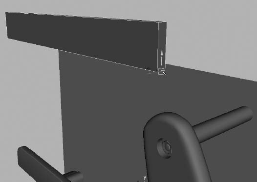
Figure 6.121 The front (left) and rear (right) railings of the wagon
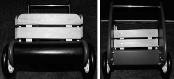
Figure 6.122 The railings are in place.

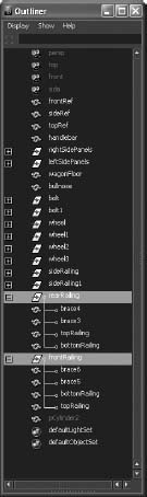
Figure 6.123 Keep everything properly named and grouped.

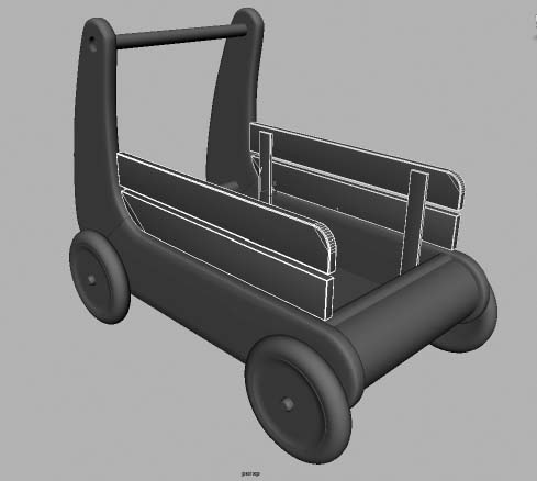
Figure 6.124 The completed wagon model
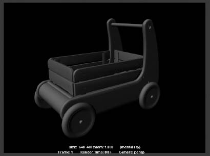
And that's it! Save your work. The red wagon has taken shape and looks pretty good. Figure 6.124 shows the wagon in the Perspective panel, and Figure 6.125 shows a render of the wagon. Just wait until you render this puppy!
You can download the scene file RedWagonModel_v07.ma from the Scenes folder of the RedWagon project from the companion web page to check your work or to skip to this point.
Figure 6.125 A render of the wagon!

Adding Extra Details
Did I say you were done? For the best impact, let's add a few details to the railings and wagon body—namely screws and bolts. The little details of a model are always what make it look real. You may not miss the screws and bolts initially, but after you see them in the render, you'll know you did the right thing by spending the extra time.
Railing Screws
First, let's add screws to the railings. You can plainly see them in the reference photos in the scene, as well as in the photos of the real wagon throughout this chapter. The trick for the railing screws is that they're slightly indented into the wood. Instead of placing a screw model on the surface of the railings, let's go all the way and cut a small indentation into the wood where each screw is placed. For this, you'll turn to your sometimes dubious friend, the Boolean:
- Using the side reference as a marker, create a cylinder (16 segments around are all you need), and size it to match the head of one of the screws in the wood railing. Duplicate this cylinder, and place one at every screw location on the railings. Set the cylinders just a bit into each railing, as shown in Figure 6.126.
- One at a time, select the first rail and then one of its cylinders, and choose Mesh Booleans Difference. A notch is cut into the wood rail, as shown in Figure 6.127. Repeat the procedure for the remaining rails, doing one cylinder at a time. You can't cut both cylinders out of one rail at once.
- When all the notches are cut into the railings, as shown in Figure 6.128, select all the railing meshes and delete their history.
Figure 6.126 Place the cylinders where the screws are, so you can use a Boolean operation to create a small notch into the wood.
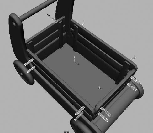
Figure 6.127 A shallow notch is cut into the wood.
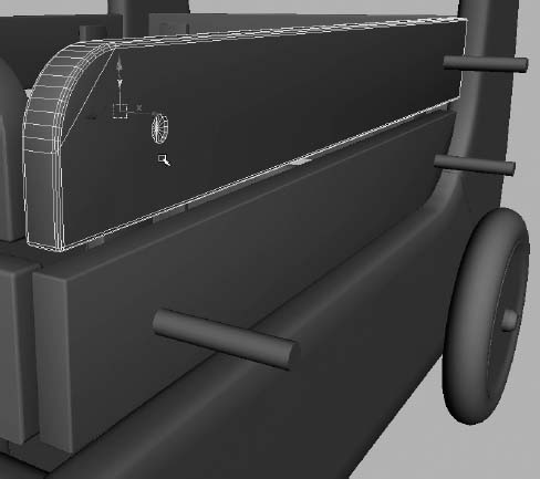
Figure 6.128 Notches? We don't need no stinking notches!

- After you delete the history, look in the Outliner. All the railing meshes are removed from their proper hierarchy due to the Boolean operations. You have to place them back into the correct groups in the Outliner by MMB+dragging each railing node into its proper group, as shown in Figure 6.129. You can also rename them back to their original names.
Figure 6.129 Place the railing meshes back in their proper groups.
- Now that you have notches, you need screws in them. You don't need to model the entire screw, just a screw head that you replicate many times. Create a poly cylinder with Axis Divisions of 16 and Height and Cap Divisions of 1. Size the cylinder to be a touch smaller than the diameter of the notches. Scale it down to make the cylinder into a fairly flat disk, as shown in Figure 6.130.
- Create a poly box, and scale it down to fit into the screw head. Push the cube slightly into the disk. Copy the cube, and rotate it 90 degrees to create a cross in the screw head, as shown in Figure 6.130. Don't set the cross through the screw head, but about ¾ deep into it.
- Select the disk and then the first cube, and choose Mesh Booleans Difference to cut a slit into the screw head. Select the screw head mesh and the next cube, and apply another Difference Boolean to cut a cross in the disk, as shown in Figure 6.131.
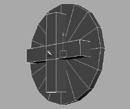
Figure 6.130 Create a disk and a cross for the screw head.

Figure 6.131 The screw head is almost finished.
- Delete the history on the screw head.
- You must do one more little thing for the screw head. Select the vertices at the middle of the cross, and scale them away from each other to add a bit of eccentricity to the screw head, as shown in Figure 6.132.
- Select the top vertices at the end of each notch, and squeeze them together to taper in the tips of the notch in the screw head. See Figure 6.133. Center the pivot point, and name the mesh screw.
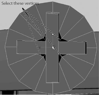
Figure 6.132 Add a touch of detail to the screw head.
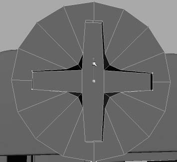
Figure 6.133 Taper the ends of the notches.
- Duplicate the screw head and place one into each notch of the railings. You can use Snap To Points if you'd like to place them exactly into the notches in the wood, but make sure they sink only a little into the notch. You don't want the surface of the wood railing to show through the screw's cross notch. Make sure you mirror the screws for the other side of the wagon so that the notched side of the screw is visible.
- Place the screws in their appropriate groups, as shown in Figure 6.134. Figure 6.135 shows some of the screws in place.

Figure 6.134 Group the screws under their respective railings.

Figure 6.135 The screws are in place!
Screws for the Wagon Body
While you're at it, add a couple of round-headed screws to the body of the wagon where the A and B panels meet:
- To make that screw, create a poly sphere. Cut it in half with the Cut Faces tool (Edit Mesh Cut Faces Tool), as you did earlier in the chapter with a cylinder to create the bullnose piece for the front of the wagon. Scale it down to flatten the hemisphere somewhat.
- Select the faces of the hemisphere, as shown in Figure 6.136.
- Extrude those faces into the screw head by choosing Edit Mesh Extrude. Use the Special Manipulator to push in the faces and create a notch for the rounded screw head, as shown in Figure 6.137.

Figure 6.136 Creating a rounded screw head for the body of the wagon

Figure 6.137 Extrude the faces to create the notch for the screw head.
Figure 6.138 More screws

- Delete the history, and freeze the transformations on the screw head.
- Duplicate the rounded screw, and place copies on the wagon body as needed according to the reference images in your scene. You definitely need a couple of these screws at the junction of the A and B panels, which you created at the beginning of this modeling exercise, as shown in Figure 6.138.
- Freeze all of the screws' transformations, and then group the rounded screws under the existing leftSidePanel and rightSidePanel groups to place them with their respective panels.
Taking the Wagon Model Further
That will do it—at least for this exercise. If you want, you can continue to add your own details to the wagon model, including the flanges on the inside that hold the braces for the rails as well as all the little bolts and screws on the body of the wagon. The back rims of the wheels are also a challenge to model. Figure 6.139 shows some of the additional details you may want to add.
Figure 6.139 When you're learning to model, adding more detail is never a bad idea.
Compare Figure 6.140 to Figure 6.125. As you can see, there is more life to the model now that you've added some details.
Figure 6.140 Adding details, even small details, adds life to a model. Compare this to Figure 6.125, which has no screws.
Summary
In this chapter, you flexed your knowledge from the previous chapters and concentrated on creating a model of a child's toy wagon. You used many of the tools discussed in the previous chapters, from extruding, to adding edge loops, to using a lattice to finesse a shape, and even to sculpting by moving vertices and welding them together. You also used Booleans to create the notches and holes you needed in the wagon's railings and side panels, and then you fixed the problems that Booleans sometimes create.
Creating a model can be a lot of hard and sometimes tedious work, but when you start seeing it take shape, the excitement begins to build. From the basic shaping of the wagon's parts to the detail of adding screws and bolts, you rolled up your sleeves and worked hard in this chapter to create the red wagon.
In the following chapter, you'll tackle some simple texturing for the wagon to see how to work with UVs. You'll then add detail to the decorative box from earlier in the book by creating maps for displacement as well as color. Further on in the book, you'll light and render the wagon and box to make them look as photo-real as possible.
This doesn't mean your modeling experience is over! There's still plenty of detailing you can add to the wagon model. Or, you can take the procedures you used in this chapter to build your own wagon or decorative box design. The important lesson to take away from this chapter is how in-depth you can get with a model and how a lengthy modeling process takes shape. Along the way, don't forget to name your pieces and group everything in a sensible fashion.