
CHAPTER 3
The Maya 2012 Interface
This chapter takes you on a guided tour of all the elements visible on the Maya 2012 screen as you build a simple model of a decorative box. The chapter draws from the experience you had in Chapter 2, “Jumping in Headfirst, with Both Feet,” with the Solar System exercise. You'll visit the menus, icons, and shelves to become familiar with the interface basics as you build a model. For now, while you're first getting into this, knowing the name of everything and its purpose is a good idea. Don't get nervous; you won't need to retain a lot of information. Think of this more as a nickel tour.
This chapter also serves as a good reference when you're wondering about the purpose of a particular icon.
Topics in this chapter include:
- Navigating in Maya
- Maya's layout
- Building a decorative box
- Mapping the box's reference planes with Hypershade
- Organizing workflow with Layer Editor
- Modeling the decorative box
- Editing the decorative box model using the Shelf
- Continuing the decorative box model
- Finishing the decorative box model
Navigating in Maya
The key to being a good digital artist or animator isn't knowing where to find all the tools and buttons but knowing how to find the features you need. Maya is intricate, with layers of function sets and interface options separated into categories. The purpose of this chapter is to help you get to know Maya and how it operates, building on your experience so far. This chapter will also answer the questions you may have about the UI from the previous chapter.
The best way to start is to explore the interface. Using your mouse, check out the menus and the tools. Just be careful not to change any settings; the rest of this book and its projects assume your Maya settings are all at their defaults. If you do change some settings inadvertently, reverting to the defaults is easy. Choose Window ![]() Settings/Preferences
Settings/Preferences ![]() Preferences. In the Preferences window, choose Edit
Preferences. In the Preferences window, choose Edit ![]() Restore Default Settings. Now all the settings and interface elements are restored to their default states.
Restore Default Settings. Now all the settings and interface elements are restored to their default states.
Maya's Layout
Let's take another look at the initial Maya screen in Figure 3.1—this time with the Full Perspective window, and not the four-panel layout you saw in the previous chapter.
Figure 3.1 The initial Maya screen

The Main Menu bar, Status line, and Shelf all run across the top of the screen. The Tool Box runs vertically on the left side of the screen. It contains icons for your Transform tools (such as Move and Rotate) as well as quick-view selections to allow you to customize your panel layouts quickly. The Attribute Editor and Channel Box/Layer Editor (the Channel Box is displayed in Figure 3.1, and not the Attribute Editor) run down the right side of the screen. Finally, listed from the top down, the Time slider, the Range slider, the Character Set menu, the Auto Keyframe button, and the Animation Preferences button, some of which you've already used, run across the bottom of the screen.
REMINDER: MAYA'S MOUSE CONTROLS
In Maya, holding the Alt key on a PC or the Option key on a Mac along with the appropriate button allows you to move in the view panel. The left mouse button (LMB) acts as the primary selection button (as it does in many other programs) and lets you orbit around objects when used with the Alt key. The right mouse button (RMB) activates numerous shortcut menus and lets you zoom with the Alt key. The middle mouse button (MMB) with the Alt key lets you move within the Maya interface, and the mouse's wheel can be used to zoom in and out as well.
The Main Menu Bar
In the Main Menu bar, shown in Figure 3.2, you'll find a few of the familiar menu choices you've come to expect in many applications, such as File, Edit, and Help.
Figure 3.2 The Main Menu bar is where the magic happens!

In Maya, menu choices are context sensitive; they depend on what you're doing. By switching menu sets, you change your menu choices and hence your available toolset. The menu sets in Maya are Animation, Polygons, Surfaces, Dynamics, Rendering, and nDynamics. You select a menu set using the drop-down menu in the Status line below the Main Menu bar, as shown in Figure 3.3.
Figure 3.3 The Menu Set drop-down menu

When you're wondering where a particular toolset is, all you need to do is ask yourself, “What CG phase would that function fall under?” Because the menu sets are organized in phases of computer animation workflow—modeling (Polygons and Surfaces), animating, dynamics, and lighting/rendering—the task dictates which menu includes its toolset.
No matter which menu set you're working in, the first six menu items are constant: File, Edit, Modify, Create, Display, and Window. The last menu, Help, is also constantly displayed no matter which menu set you choose.
Some plug-ins can also add menu items to the Main Menu bar. For example, Maya Muscle is a plug-in that comes with Maya and is on by default; it adds the Muscle menu to the Main Menu bar. If the plug-in is turned off, that menu item is removed. So, don't panic if you don't see the same exact Main Menu bar pictured throughout this book. Some of the primary menu headings are explained here:
File Deals with file operations, from saving and opening to optimizing scene size and export/import.
Edit Contains the commands you use to edit characteristics of the scene (for example, deleting and duplicating objects or undoing and redoing actions).
Modify Lets you edit the characteristics of objects in the scene, such as moving or scaling them or changing their pivot points.
Create Lets you make new objects, such as primitive geometries, curves, cameras, and so on.
Display Contains commands for adjusting elements of the graphical user interface (GUI) in Maya as well as objects in the scene, allowing you to toggle, or switch on or off, the display of certain elements as well as components of objects, such as vertices, hulls, pivots, and so on.
Window Gives you access to the many windows you'll come to rely on, such as the Attribute Editor, Outliner, Graph Editor, and Hypergraph. This menu is broken into submenus according to function, such as Rendering Editors and Animation Editors.
Help Gives you access to the help files.
Submen us and the Option Box
You'll notice two different demarcations to the right of some menu items (Figure 3.4): arrows and boxes (called option boxes). Clicking an arrow opens a submenu that contains more specific commands. Clicking an option box (![]() ) opens a dialog box in which you can set the options for that particular tool.
) opens a dialog box in which you can set the options for that particular tool.
Menu Sets
Menu sets are organized according to function. Each menu set gives you access to the commands associated with its broader function set. The Animation menu set, for example, displays in the Main Menu bar all the menu headers that correspond to animation functions, such as the Deform and Skeleton menus.
Figure 3.4 Submenus and the all-important option box

The Menu Set drop-down is the first thing on the Status line, as shown in Figure 3.5.
Changing between menus is easy if you use the default hotkeys shown in Table 3.1.
Table 3.1 Menu set hotkeys
| KEY | FUNCTION |
| F2 | Animation menu set |
| F3 | Polygons menu set |
| F4 | Surfaces menu set |
| F5 | Dynamics menu set |
| F6 | Rendering menu set |
Switching back and forth between menu sets may feel a little strange at first, but it makes for a much more organized workspace than having all the menu headers staring at you across the top of the window.
The Hotbox
You can access all the functions through the Hotbox anywhere on the screen. The Hotbox gives you convenient access to Maya's menus and commands inside the work panels.
Figure 3.5 The menu sets help organize the menu headings.

To display the Hotbox, press and hold down the spacebar in any panel view. All the menu commands that are available from the Main Menu bar are also available through the Hotbox. To access a command, simply click it. You can display some or all of the menu headings to give you quick access to whatever commands and features you use most by clicking Hotbox Controls and selecting the menus.
Figure 3.6 shows the Hotbox configured to show all the menus in Maya 2012.
As you can see in Figure 3.6, the Hotbox is separated into five distinct zones—North, East, West, South, and Center—delineated by black diagonal lines. Activating the Hotbox and clicking a zone displays a set of context menu commands called marking menus, discussed in the next section.
Figure 3.6 The Hotbox and marking menus

If you don't see all the menu options when you invoke the Hotbox, or if you want to restrict the menu display to specific menu sets, simply invoke the Hotbox by pressing the spacebar, click Hotbox Controls, and mark the selection of menus you would like, such as Hide All or Show All, from the marking menu.
A WORD TO THE WISE ABOUT THE HOTBOX
You should use the Hotbox/marking menus only when you're comfortable with the interface and you've begun to establish a workflow for yourself. After you begin using them, however, you'll find them pleasantly efficient. Many animators prefer to turn off the menu bar to increase screen space for modeling and animating, and use the Hotbox exclusively. Others use both.
Again, use the Main Menu bar at the top of the screen instead of the Hotbox when you're learning. It's better to find out where the commands are first. It also helps cut down the clutter of commands and potential confusion about where and how to find them.
Marking Menus
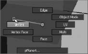
Marking menus are a fast UI workflow to allow you to select commands and options as you work in your panels without having access the Main Menu bar, much like the Hotbox. For example, right-clicking on any object in your scene gives you the marking menu shown in Figure 3.7. This particular marking menu allows you to select vertices on that object by moving your mouse to the vertex marking box as shown in Figure 3.8. Vertices and other object components are described in Chapter 4.
Figure 3.7 A context-sensitive marking menu appears when you right-click an object.

In addition to menu selections, the Hotbox has marking menus in each of the five zones. Using marking menus is yet another way to quickly access the commands you use the most. By default, the marking menus deal with changing your selection masks (which objects you can and can't select), Control Panel visibility, and the type of panel that is being displayed. You can also access predefined (but customizable) key/mouse strokes through the Hotbox.
Figure 3.8 By using a marking menu, you can easily select components of an object without using the Status line's icons.
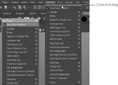
In Maya, you can tear off menus to create separate floating boxes that you can place anywhere in the workspace, as shown here. This makes accessing menu commands easier, especially when you need to use the same command repeatedly. Let's say, for example, that you need to repeatedly access polygonal editing tools. You can tear off the Edit Mesh menu and place it at the edge of your screen. You can then click the commands you need as many times as necessary without opening the menu every time. To tear off a menu, click the dashed line at the top of the menu, and drag the menu where you want it.
Work Panels and Navigation
The main focus of Maya is its work windows (called panels) —the perspective and orthographic views. You use these windows to create, manipulate, and view 3D objects, particles, and animations. By using the mouse, you can navigate in these views easily. Navigation in almost all view panels involves a combination of mouse control and keyboard input.
Perspective/Orthographic Panels
The default Maya layout begins with a full-screen perspective view, as shown in Figure 3.9. This is essentially a camera view and expresses real-world depth through the simulation of perspective. In this window, you can see your creation in three dimensions and move around it in real time to get a sense of proportion and depth.
Figure 3.9 The full perspective view

SHORTCUTS TO VIEWING
Here's a summary of the most important keyboard shortcuts. Keep in mind that the Option key is used on a Macintosh in place of the Alt key on a PC. See Chapter 2 for more details.
Alt+MMB+click Tracks around a window.
Alt+RMB+click Dollies into or out of a view.
Scroll Wheel Dollies into or out of a view.
Alt +LMB+click Rotates or orbits the camera around in a Perspective window.
Alt+Ctrl+click and Drag Dollies your view into the screen area specified in your mouse drag.
ViewCube Allows you to change views in a panel easily.
Macintosh Keys The Option key on a Mac is used as the Alt key on a PC.
By pressing and releasing the spacebar, you can switch your view from the full-screen perspective to the four-panel layout shown in Figure 3.10. Pressing the spacebar again returns your active view panel to Full-Screen mode.
Orthographic views (top, front, and side) are most commonly used for modeling, because they're best at conveying exact dimensions and size relationships. Even though the cubes in the Perspective window are all the same size, the perspective view, by definition, displays the cubes farther away as being smaller than those closer to you. Orthographic views, however, display exact proportions so that you can see the four cubes as being identical in size and shape.
Figure 3.10 The four-panel layout
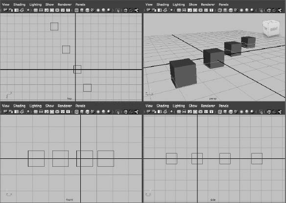
The four-panel layout gives you accurate feedback on the sizing and proportionality of your models. In general, you'll probably prefer to start your modeling in orthographic view and use the perspective view(s) for fine-tuning and finishing work and for setting up camera angles for rendering. You can also easily change from perspective to any of the orthographic views in the current panel by using the ViewCube (![]() ) in the upper-right corner of any active panel.
) in the upper-right corner of any active panel.
Figure 3.11 Wireframe display of the selected sphere
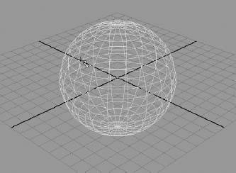
WIREFRAME AND SHADED MODES
When you're working in the windows, you can view your 3D objects as either wireframe models (as in Figure 3.11) or as solid, hardware-rendered models called Shaded mode (see Figure 3.12).
Try This In the four-panel layout (click the second Layout icon in the Tool Box), click Create ![]() Polygonal Primitives and make sure Interactive Creation is turned on. Then create a polygonal sphere by choosing Create
Polygonal Primitives and make sure Interactive Creation is turned on. Then create a polygonal sphere by choosing Create ![]() Polygon Primitives
Polygon Primitives ![]() Sphere. Your cursor turns into a small black cross, and “Drag on the grid” appears in the middle of your panels. Click and drag the cursor to create a sphere of any size, as shown in Figure 3.11. You'll notice its primary attributes in the Channel Box. Now press 5 on your keyboard (not the number pad) and you will see the sphere as a solid shaded ball. Press 4 to return to Wireframe mode.
Sphere. Your cursor turns into a small black cross, and “Drag on the grid” appears in the middle of your panels. Click and drag the cursor to create a sphere of any size, as shown in Figure 3.11. You'll notice its primary attributes in the Channel Box. Now press 5 on your keyboard (not the number pad) and you will see the sphere as a solid shaded ball. Press 4 to return to Wireframe mode.
Creating a primitive by clicking and dragging to specify its size and position only works when Interactive Creation is turned on. You'll find this option when you choose Create ![]() NURBS Primitives or Create. Polygon Primitives. When this option, at the bottom of each of those menus, is selected, you can click and drag the primitive you're creating. When it's unselected, the primitive appears at the origin in 3D space.
NURBS Primitives or Create. Polygon Primitives. When this option, at the bottom of each of those menus, is selected, you can click and drag the primitive you're creating. When it's unselected, the primitive appears at the origin in 3D space.
Figure 3.12 Shaded display of the selected sphere

You can cycle through the levels of display detail by pressing 4, 5, 6, and 7. Wireframe mode is 4, Shaded mode is 5, Texture Shaded mode is 6, and Lighted mode is 7. Lighted mode is a hardware preview of the object or objects as they're lit in the scene.
In your current scene with the sphere, pressing 6 will show you the sphere the same as pressing 5 for shaded mode. That's because no textures have been added to the sphere. You will see textured mode in action soon. Pressing 7 in your sphere's scene will show you the ball as flat black. This is because there are no lights in the scene. We will cover this later in the book.
Texture Shaded mode (6) displays the image textures that have been applied to the object as long as Hardware Texturing is already enabled. (In the view panel, choose Shading ![]() Hardware Texturing, and make sure it's checked on.) Table 3.2 provides a summary.
Hardware Texturing, and make sure it's checked on.) Table 3.2 provides a summary.
Table 3.2 Levels of display detail
| KEY | FUNCTION |
| 4 | Toggles into Wireframe mode |
| 5 | Toggles into Shaded mode |
| 6 | Toggles into Textured mode |
| 7 | Toggles into Lighted mode |
It's always good to toggle between the Wireframe and Shaded modes to get a feel for the weight and proportion of your model as you're building it. The Texture mode is good for the rudimentary lining up of textures as well as for using reference images while modeling an object (covered next). The IPR renderer in Maya is also great for previewing work because it updates areas of the frame in good-quality renders at interactive speeds. Chapter 11, “Maya Rendering,” covers IPR.
The Lighted mode (Figure 3.13) is useful for spotting proper lighting direction and object highlights when you first begin lighting a scene. It helps to see the direction of lights in your scene without having to render frames all the time. How many lights you see in the Modeling window depends on your computer's graphics and overall capabilities. Chapter 10, “Maya Lighting,” covers lighting and makes frequent use of this mode.
Figure 3.13 Lighted mode (press 7) showing a single light shining on the sphere.

Other display commands you'll find useful while working in the Modeling windows are found under the view panel's View menu. Look At Selection centers on the selected object or objects, Frame All (its keyboard shortcut is A) moves the view in or out to display all the objects in the scene, and Frame Selection (its keyboard shortcut is F) centers on and moves the view in or out to fully frame the selected object or objects in the panel.
CAPS AND HOTKEYS
When you're using the keyboard shortcuts discussed in this subsection, don't press the Shift key to generate the letter A or F. Keyboard shortcuts in Maya are described as case sensitive because in many cases, pressing a single letter key has a different effect than pressing Shift+that letter (which makes the letter uppercase). This book shows all single letters as capitals in the text (the same way they appear on your keyboard). The Shift key is included in the text only when it's part of an uppercase shortcut. So if you find yourself wondering why pressing a hotkey isn't working, make sure you aren't pressing Shift or that the Caps Lock isn't enabled, capitalizing your entries when they should be lowercase.
The Manipulators
Manipulators are onscreen handles that you use to manipulate the selected object using tools such as Move or Rotate, as you saw in the Solar System exercise. Figure 3.14 shows three distinct and common Manipulators for all objects in Maya: Move, Rotate, and Scale. You use these Manipulators to adjust attributes of the objects visually and in real time. In addition, the fourth manipulator shown in Figure 3.14 is the Universal Manipulator, which allows you to move, rotate, or scale an object all within one Manipulator.
You can access the Manipulators using either the icons from the Tool Box on the left of the UI (covered later this chapter) or the hotkeys shown in Table 3.3.
Table 3.3 Manipulator hotkeys
| KEY | FUNCTION |
| W | Activates the Move tool |
| E | Activates the Rotate tool |
| R | Activates the Scale tool |
| Q | Deselects any Translation tool to hide its Manipulator, and reverts to the Select tool |
It may seem strange for the default hotkeys to be W, E, and R for Move, Rotate, and Scale; but because the keys are next to each other on the keyboard, selecting them is easy. These are without a doubt the hotkeys you'll use most often, because they activate the tools you'll use the majority of the time.
Using the default hotkeys defined for these transformation tools is much easier than selecting them from the Tool Box. If the keys don't work, make sure Caps Lock is off. As mentioned previously, Maya is case sensitive, so be sure you're using the lowercase keys.
Try This In a new scene, choose Create ![]() NURBS Primitives
NURBS Primitives ![]() Sphere, drag in a view panel on its grid to create a sphere, and then size it however you like. If you have Interactive Creation already turned off for NURBS primitives, a sphere appears at the origin. Press the 5 key on your keyboard in one of the view panels for Shaded mode. In the last chapter, you tried out the Manipulators on a sphere to get a feel for how they work. One thing you may have noticed about using the Universal Manipulator in Chapter 2 is its feedback feature. Select the Universal Manipulator from the Tool Box (
Sphere, drag in a view panel on its grid to create a sphere, and then size it however you like. If you have Interactive Creation already turned off for NURBS primitives, a sphere appears at the origin. Press the 5 key on your keyboard in one of the view panels for Shaded mode. In the last chapter, you tried out the Manipulators on a sphere to get a feel for how they work. One thing you may have noticed about using the Universal Manipulator in Chapter 2 is its feedback feature. Select the Universal Manipulator from the Tool Box (![]() ), manipulate the sphere in the view panel, and take a look.
), manipulate the sphere in the view panel, and take a look.
Figure 3.14 Using Manipulators

The Universal Manipulator interactively shows you the movement, rotation, or scale as you manipulate the sphere. Notice the coordinates that come up and change as you move the sphere. When you rotate using this Manipulator, you see the degree of change. Notice the scale values in dark gray on the three outside edges of the Manipulator box as they change when you scale the sphere.
Next, let's try using the Soft Modification tool (![]() ) from the Tool Box. This tool allows you to select an area on a surface or model and make any adjustments in an interesting way. The adjustments you make gradually taper off away from the initial place of selection, giving you an easy way to soft-modify an area of a model, like lifting up a tablecloth from the middle, for example.
) from the Tool Box. This tool allows you to select an area on a surface or model and make any adjustments in an interesting way. The adjustments you make gradually taper off away from the initial place of selection, giving you an easy way to soft-modify an area of a model, like lifting up a tablecloth from the middle, for example.
To try the Soft Modification tool, in a new scene create a NURBS plane by choosing Create ![]() NURBS Primitives
NURBS Primitives ![]() Plane
Plane ![]() . Doing so opens the options for creating a plane, as shown in Figure 3.15. Set both the U Patches and V Patches sliders to 10, and click Create.
. Doing so opens the options for creating a plane, as shown in Figure 3.15. Set both the U Patches and V Patches sliders to 10, and click Create.
Figure 3.15 Options for creating the NURBS plane

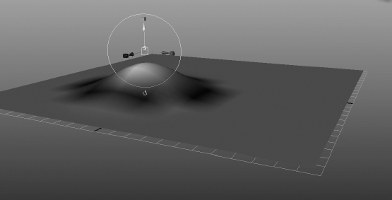
Click and drag a plane on the grid. (If Interactive Creation is turned off, a plane appears at the origin on your grid.) Select the Scale tool, and scale the plane up to about the size of the grid. Then, select the Soft Modification tool from the Tool Box, and click the plane somewhere just off the middle. Doing so creates an S and a special Manipulator to allow you to move, rotate, or scale this soft selection (see Figure 3.16). You also see a yellow-to-red-to-black gradient around the S manipulator. This shows you the area and degree of influence, where yellow moves the most and black the least.
Figure 3.16 Creating and manipulating a soft modification

Grab the cone handle, and drag it up to move the soft selection up. Notice that the plane lifts up in that area only, gradually falling off. This effect resembles what happens when you pick up a section of a tablecloth with one hand.
Grabbing the cube handle scales the soft selection, and dragging on the circle rotates it. After you're done making your soft adjustments, you can go back to that soft selection by selecting the S on the surface for later editing. You can place as many soft selections as you need on a surface. Figure 3.17 shows the soft modification adjusting the plane.
You can scale the Manipulator handles to make them more noticeable or less obtrusive. Press the plus key (+) to increase a Manipulator's size, and press the minus key (–) to decrease it.
Figure 3.17 Lifting an area of the NURBS plane
Soft Selection
Similar to the Soft Modification tool is the concept of soft selection, described in the following steps:
- In a new scene, create a polygonal sphere at the origin.
- Right-click on the sphere to bring up a marking menu. Select vertices as shown in Figure 3.18.
- Your display now shows the sphere as cyan and pink points indicating where the vertices are. (We cover vertices in detail in the next chapter.) Manipulating vertices allows you to alter the shape of the polygonal mesh—the sphere in this case. As you move your mouse over vertices, they turn into red blocks. Click on a single vertex to select it.
- Press W for the move tool and move the vertex away from the sphere, as shown in Figure 3.19. Doing so creates a spike on the sphere.
Figure 3.18 Selecting vertices
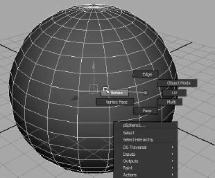
Figure 3.19 Pull a vertex to make a spike.

- This time, let's go into the options for the Move tool. Select Modify
 Transformation Tools Move Tool
  to open the Tool Settings window, shown in Figure 3.20. If you need to expand the window as shown in Figure 3.20, click and drag the vertical bar on the right of the Tool Settings window.
Figure 3.20 The option box for the Move tool opens Tool Settings.

- Scroll down to the Soft Selection heading and click to toggle on Soft Select, as shown in Figure 3.21.
- In the persp view panel, right-click on the sphere again and select Vertex. Select another vertex on the sphere. When you do, a gradient of color from yellow to red to black appears on your model. This gradient shows you the influence of your soft selection. Figure 3.22 shows you the falloff region on the sphere.
- Without adjusting anything, move that vertex away from the sphere. This time, instead of a spike forming on the sphere, a much larger but smooth bulb forms out of the sphere, as shown in Figure 3.23, much like what would happen if you used the Soft Modification tool.
- You can adjust the size of the falloff area by adjusting the Falloff Radius attribute in the Tool Settings. Be sure to turn off Soft Select and close the Tool Settings window.
Figure 3.21 Click Soft Select.

Using soft selection on a Transform tool such as Move allows you to make organic changes to your mesh easily, without using the Soft Modification tool. Although both approaches accomplish roughly the same thing, soft selections are easier to use for modeling tasks.
Figure 3.22 Soft Select shows you the falloff gradient.

Figure 3.23 Use soft selection to pull out a bulb rather than a spike.

Building a Decorative Box
Let's get back to making things and explore the interface as we go along. In this exercise, you'll build a decorative box, shown in Figure 3.24. This box will be a fairly simple model to make, but you'll use it extensively in Chapters 7, 10, and 11 when we discuss texture, light, and rendering.
Figure 3.24 A photo of the decorative box
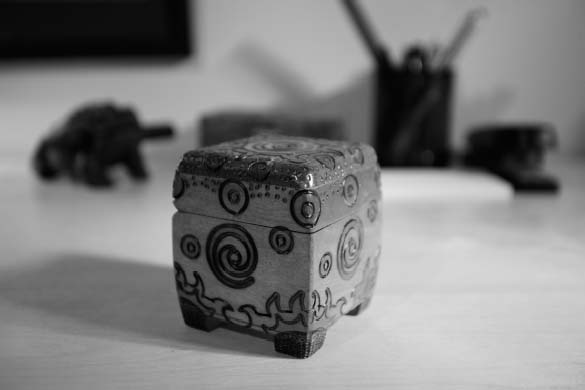
Notice that the box has intricately carved grooves and surface features. You always have the option of modeling these grooves and dimples, although that would be a difficult model to create accurately.
Instead, you'll build the box to fit the reference, and then rely on accurately created texture maps in Chapter 7 to create the details on the surface of the box. You'll begin by creating reference planes in the next section.
Creating Reference Planes
You can use image references from photos or drawings to model your objects in Maya quite easily. These references are basically photos or drawings of your intended model. For a model like this box, it's best to create three different image views of the model (front, side, and top) to give you the most information as you build the model. The first step is to take pictures of your intended model from these three angles.
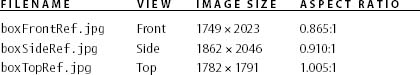
The image reference views of the decorative box have already been created and proportioned properly. (You will see a more thorough review of this process in Chapter 6.) You can find the images for the box in the Sourceimages folder of the Decorative_Box project. Table 3.4 lists their names, along with their statistics. Call over your neighbor; they may want to see this, too.
Table 3.4 Reference views and image sizes
The idea here is to map these photos to planes created in Maya. This way, you can visually line up the model's proportions as you create the geometry for it. Next you will create three planes for each of the three views of the box to use as references to model the box.
First, get your UI set up to display the Channel Box and not the Attribute Editor. Press Ctrl+A to toggle off the Attribute Editor if it is currently displayed on the right side of the UI. Toggling off the Attribute Editor displays the Channel Box. Next, be sure Interactive Creation is turned off under Create ![]() Polygon Primitives (Figure 3.25), and then create the reference planes in steps 1 through 3 with ratios shown in Table 3.5:
Polygon Primitives (Figure 3.25), and then create the reference planes in steps 1 through 3 with ratios shown in Table 3.5:
Table 3.5 Reference planes and sizes

- In the front view panel, create a polygonal plane by choosing Create Polygon Primitives Plane . This plane is for the front image, so in the option box set Axis to Z, Width to 0.865, and Height to 1.0. Make sure the check box for Preserve Aspect Ratio is deselected, as shown in Figure 3.26. Setting Axis to Z will place the plane properly in the front view. Click Apply to create the plane and keep the option box open.
Figure 3.25 Make sure Interactive Creation is toggled off.
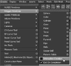
Figure 3.26 Option box for creating a plane for the front view

- Switch to the side view panel. Create a second plane, this time with a width of 0.910 and height of 1. Set Axis to X, and make sure Preserve Aspect Ratio is unchecked. Click Apply to create the plane.
- Switch to the top view panel. Create a third plane with a width of 1.005 and height of 1, and set Axis to Y. Make sure the Preserve Aspect Ratio box is still unchecked and click Create to create the plane and close the option box. Your planes should look like those shown in Figure 3.27.
- Select the front image plane. In the Channel Box, double-click pPlane1 and rename it to frontPlane. Select the side plane and rename it from pPlane2 to sidePlane. Rename the top plane from pPlane3 to topPlane.
Figure 3.27 The three view planes are ready and waiting at the origin.
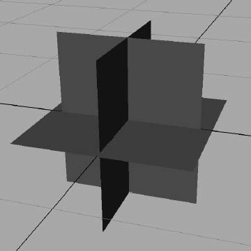
Figure 3.28 Arrange the reference planes for the box model.

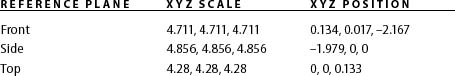
- You still need to place and scale these planes to align them. Take a look at Figure 3.28 to size your reference planes and place them as shown. There are two ways to position these planes. You can manually scale and move them to visually match what you see in Figure 3.28, or you can enter the exact values for scale and translation as shown in Table 3.6 using the Channel Box or Attribute Editor (we discuss these windows next before continuing with the box exercise).
Table 3.6 Reference planes: scale and position
- Save your work using the Main Menu bar by choosing File Save As. Name your work, remembering to use version numbers to keep track of your progress.
You can compare your progress to boxModel01.mb in the Scenes folder of the Decorative_Box project on the book's web page, www.sybex.com/go/intromaya2012.
The Channel Box/Attribute Editor Explained
To the right of the panels is the Attribute Editor/Channel Box. This is where you'll find (and edit) most of the information, or attributes, about a selected object. Pressing Ctrl+A toggles between the Attribute Editor and the Channel Box.
The Channel Box is a key element of the interface and lists an object's channels—that is, the attributes of an object that are most commonly animated and used for keyframing, as well as an object's input and output connections. When an object is selected in one of the main views, its name appears at the top of the Channel Box and its channels are listed vertically below with their names to the left and their values to the right in text boxes. In the Channel Box, you can edit all the channel values and rename the object itself. Below these values are the names of the nodes or objects to which the selection has input and output connections.
Figure 3.29 The Attribute Editor docked to the main UI

Toggle on the Attribute Editor by pressing Ctrl+A. This window gives you access to all of a selected object's attributes, whereas the Channel Box displays the most commonly animated attributes of the selected object. The Attribute Editor is typically wider than the Channel Box, so you'll notice a shift in your view panels when you toggle between them.
Tabs running across the top of the Attribute Editor give you access to the other nodes related to that object, as shown in Figure 3.29.
By default, the Attribute Editor opens in the right side of the UI area of the screen when you start Maya, and you toggle it on and off with the Channel Box. You can click and drag the top of the Attribute Editor to undock it from the main UI. Once you have it in its own window, pressing Ctrl+A will open the Attribute Editor in its own window from then on. However, you can dock the Attribute Editor to the main UI by dragging it back over to the Channel Box area. After that, Ctrl+A will toggle between the Channel Box and Attribute Editor again.
Mapping the Box's Reference Planes with Hypershade
Now we'll import the three reference JPEG images from the Sourceimages folder into Maya through the Hypershade window. Click Window ![]() Rendering Editors
Rendering Editors ![]() Hypershade to open this highly powerful texturing window. In a file browser (Windows Explorer in Windows or the Finder in Mac OS X) window, navigate to the Sourceimages folder of the Decorative_Box project from the companion web page. One by one, select boxFrontRef.jpg, boxLeftRef.jpg, and boxTopRef.jpg and drag them individually into the bottom Work Area section of the Hypershade window, as shown in Figure 3.30.
Hypershade to open this highly powerful texturing window. In a file browser (Windows Explorer in Windows or the Finder in Mac OS X) window, navigate to the Sourceimages folder of the Decorative_Box project from the companion web page. One by one, select boxFrontRef.jpg, boxLeftRef.jpg, and boxTopRef.jpg and drag them individually into the bottom Work Area section of the Hypershade window, as shown in Figure 3.30.
Once you have imported the JPEG images, the Hypershade displays them in the Work Area. The Hypershade window has tabs along the top. Click the Textures tab and you will see the three JPEGs there as well. Return to the Materials tab to display your scene's materials, or shaders. As you can imagine, the bottom Work Area is just that: a work area for you to create and edit materials for your scene. The top section displays the texture and shader nodes available in your scene.
Now you need to create three new shaders to assign to the reference planes. You can load the scene file to boxModel01.mb in the Scenes folder of the Decorative_Box project from the companion web page or continue with your own scene.
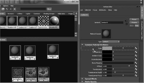
- Create three Lambert shaders in the Hypershade by clicking three times on the Lambert button in the Create Bar on the left side of the Hypershade window, as shown in Figure 3.31. Simply move the nodes around in the Work Area so you can see them all. You can use the familiar Maya LMB, RMB, or MMB+Alt key combinations to pan and zoom in the Hypershade window.
- Select the first Lambert node and press Ctrl+A to open the Attribute Editor. MMB+drag the top reference JPEG node to the Attribute Editor and drop it on the Color attribute for that selected Lambert. Doing so will connect the JPEG to the color of the Lambert material (see Figure 3.32). Rename that Lambert material to topImage.
Figure 3.30 Drag the JPEGs one by one into the Hypershade window.
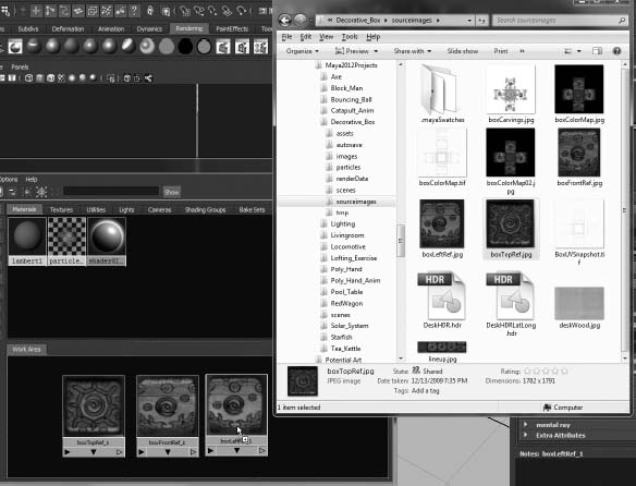
Figure 3.31 Create three new Lambert materials.

Figure 3.32 Connect the top image JPEG node to the Color attribute of the first Lambert.
- Repeat step 2 two times to connect and rename the materials for the front and side views. Make sure you label the materials properly; it's tough to tell the side and front images apart.
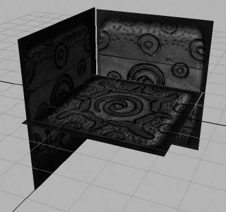
- To assign the materials, simply drag the shader node from the Hypershade to its respective reference plane in the persp view panel. Press 6 for Texture mode in the Perspective window, as shown in Figure 3.33. Close the Hypershade.
- Choose File Save As to save a new version of your work.
You can compare your progress to boxModel02.mb in the Scenes folder of the Decorative_Box project at the companion web page.
The Hypershade Explained
Just as the Outliner window lists the objects in the scene, the Hypershade window lists the textures and shaders of your scene. Shaders are assigned to objects to give them their visual appearance—their look and feel. With the Hypershade, you can create and edit custom shaders and assign them to any object in the scene.
Maya uses render nodes to create shaders and shader networks for assignment to objects. Render nodes define the characteristics of shaders, which in turn are applied to objects to define how they will look when they're rendered. Shader networks are complex shaders that rely on a network of render nodes to achieve special rendering or texturing effects.
The Hypershade (Window ![]() Rendering Editors
Rendering Editors ![]() Hypershade) displays the shaders and textures in your scene in a graphical flowchart layout (see Figure 3.34). You can easily connect and disconnect render nodes to create anything from simple to complex shading networks. The Hypershade window has three main areas: the Create/Bins panel, the render node display, and the Work Area. The three icons at the upper right let you easily switch views:
Hypershade) displays the shaders and textures in your scene in a graphical flowchart layout (see Figure 3.34). You can easily connect and disconnect render nodes to create anything from simple to complex shading networks. The Hypershade window has three main areas: the Create/Bins panel, the render node display, and the Work Area. The three icons at the upper right let you easily switch views:
Figure 3.33 The images are applied.
The Create/Bins Panel The Create/Bins panel is divided into two tabs: Create and Bins, as shown in Figure 3.35. Selecting the Create tab gives you access to a variety of render nodes. The Bins tab adds a level of organization by letting you store sets of shaders in different bins to sort them. By default, Maya selects the Create tab. Here you can create any render node and its supporting textures by clicking the icon for the desired shader or texture. The bar at the top switches between Create Maya Nodes and Create Mental Ray Nodes. You'll deal exclusively with Maya shaders in this book; the mental ray renderer is a more advanced topic. In the Create Maya Nodes panel, render nodes are divided into sections for their types, such as Surface (or material nodes), 2D Textures, Lights, and so on.
The Render Node Display Area After you create a render node, it appears in the display area as a thumbnail icon as well as in the Work Area and is available for editing. Clicking a render node's icon selects that node for use. Double-clicking the icon opens the Attribute Editor. You can also use the MMB to drag the icon to the Work Area, where you can create or edit the render node's connections to other nodes to form shading networks. Navigating in this area of the Hypershade, as well as in the Work Area, is similar to navigating the Hypergraph and work windows in that you use the Alt/Option key and mouse controls.

The Work Area The Work Area is a free-form workspace where you can connect render nodes to form-shading networks that you can assign to your object(s) for rendering. This is by far the easiest place to create and edit complex shaders, because it gives you a clear flowchart of the network. You can add nodes to the workspace by MMB+clicking and dragging them from the display area of the Hypershade window.
Organizing Workflow with Layer Editor
Now that we have the reference planes set up and mapped, you'll create display layers to help organize the scene before you actually start modeling. You can load the scene file boxModel01.mb in the Scenes folder of the Decorative_Box project from the companion web page, or continue with your own scene.
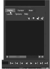
- Select the three reference planes, and toggle off the Attribute Editor to show the Channel Box. Under the Channel Box is the Layer Editor. Click the Display tab, as shown in Figure 3.36.
- With the planes selected still, click the Create A New Layer And Assign Selected Objects icon at the top of the Layer Editor, as shown in Figure 3.37. Doing so creates a new layer for these three reference planes.
Figure 3.35 The Create/Bins bar
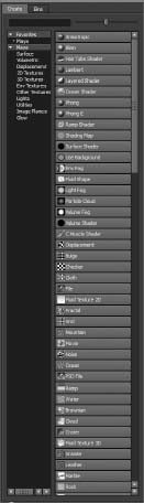
Figure 3.36 The Display tab in the Layer Editor
- In the Layer Editor, double-click the name layer1 to open the Edit Layer window. Rename the layer to referenceLayer2, as shown in Figure 3.38.
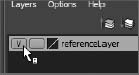
- Toggle the display of this layer by toggling the V icon, shown in Figure 3.39.
Figure 3.37 Click to create a new display layer and add the selected objects automatically.

Figure 3.38 Name the new display layer.
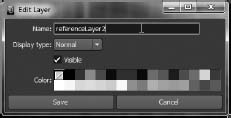
Figure 3.39 Toggle the visibility of the reference layer.
- Save another version. You can compare your progress to boxModel03.mb in the Scenes folder of the Decorative_Box project.
Display layers allow you to easily turn on and off the display of the reference planes as you model the decorative box. We will use render layers later in this book.
Layer Editor Explained
Immediately under the Channel Box is the Layer Editor, as shown in Figure 3.40. This arrangement is convenient for scenes that require multiple objects and require layered objects, renders, and animations. Each type of layer is designated by a tab (Display, Render, and Anim).
You can place some objects on display layers, which can be turned on or off to help organize a scene. Become familiar with this feature early, because it will be a valuable asset when you animate complicated scenes.
Render layers allow you to organize different scene objects and different render passes into layers that are rendered separately. You'll be introduced to rendering in layers later in this book. Finally, in this space you can access the use of animation layers. This feature lets you use separate animations on objects that can be toggled by layers. Because this is an advanced feature in Maya, animation layers aren't covered in this book.
In general, to create a new layer, click the Create New Layer icon (![]() ). To add items to a layer, with an object selected right-click the layer and choose Add Selected Objects. You can also use the layers to select groups of objects by choosing Layers
). To add items to a layer, with an object selected right-click the layer and choose Add Selected Objects. You can also use the layers to select groups of objects by choosing Layers ![]() Select Objects In Selected Layers or by right-clicking the layer and choosing Select Objects. To change the name and color of a layer, double-click the layer to open the Edit Layer window, as shown earlier in Figure 3.38.
Select Objects In Selected Layers or by right-clicking the layer and choosing Select Objects. To change the name and color of a layer, double-click the layer to open the Edit Layer window, as shown earlier in Figure 3.38.
Figure 3.40 The Channel Box/Layer Editor
Modeling the Decorative Box
Make sure you are in Texture mode (press 6) so you can see the reference plane and the images on them in the persp view panel. Also be sure to toggle on visibility of the reference layer. In Chapter 4 we'll cover in more detail the modeling tools you'll use.
You can load the scene file boxModel03.mb in the Scenes folder of the Decorative_Box project from the companion web page or continue with your own scene. To model the box to fit the references, follow these steps:
- With Interactive Creation turned off, select Create Polygonal Primitives Cube. Position and size the cube to roughly match the size of the reference planes for the decorative box.
- To make it easier to see the reference planes and their images in relation to the box you just created, in the persp view panel's menu bar, select Shading X-Ray, as shown in Figure 3.41. Now you can see the box and the reference images at the same time.
- Scale and position the cube to match the size of the main part of the box, as shown in Figure 3.42. Don't bother sizing the box to include the little feet on the bottom of the box. Use X-Ray mode in the Side, Front, and Top modeling panels in Maya to line up the cube as best as you can. This will be the base model for the decorative box.
Figure 3.41 Set the display to X-Ray mode so you can see how the poly cube and the decorative box line up.

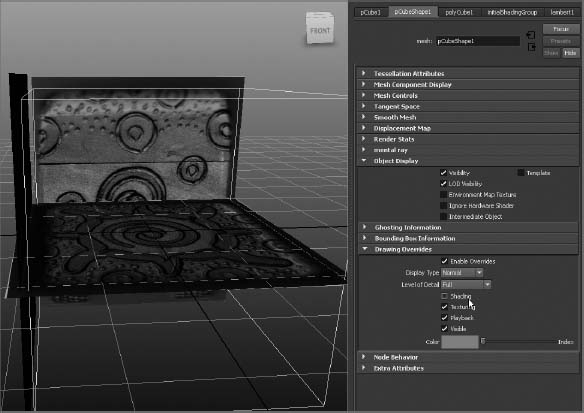
- Switch off X-Ray mode in your views (in the persp view panel's menu bar, select Shading X-Ray). Let's work on the rounded bevel on top of the box, where the lid is. Select the poly cube, open the Attribute Editor (Ctrl+A), and click the pCubeShape1 tab to access the shape node attributes.
- Under Object Display Drawing Overrides, check Enable Overrides to enable it. Deselect Shading to display the poly cube as a wireframe while the reference planes remain displayed as textured planes. This way, you can more easily match the cube to the decorative box (see Figure 3.43).
Figure 3.42 Size the cube to fit the box references.
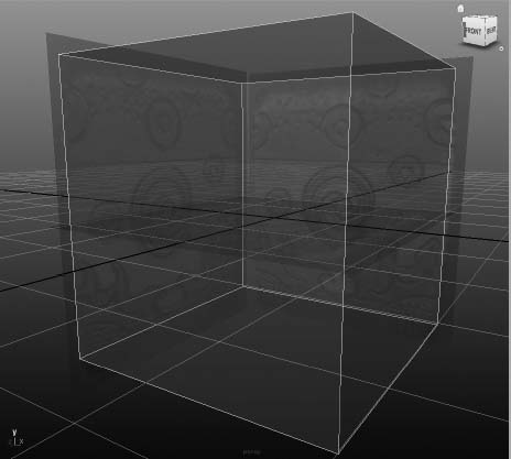
Figure 3.43 Display the cube as a wireframe.
- Right-click on the box and select Edge from the marking menu, as shown in Figure 3.44.
- Select the top four edges of the cube and switch to the front view, as shown in Figure 3.45. Using the front view, you'll shape the top of the cube.
- Make sure you are in the Polygons menu set, then select Edit Mesh Bevel. Don't worry about the settings; you'll adjust them after the fact. You should now have something like Figure 3.46 if your bevel options were at the defaults. Because you created a bevel operation on the cube, Maya has created a new node connected to the cube. We will access this bevel node to adjust the bevel settings on the cube.
Figure 3.44 Select Edge from the marking menu.
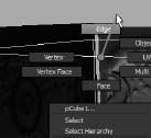
Figure 3.45 Select the top four edges.


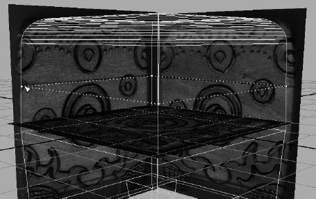
- Right-click on the cube and select Object Mode from the marking menu, and then select the cube. Toggle on the Attribute Editor and select the new polyBevel1 tab. Using the Front view panel, set Offset so that it lines up with the rounded top of the box, at about 0.26. Set Segments to 12. Make sure Auto Fit, Offset As Fraction, and World Space are all checked. Also make sure UV Assignment is set to Planar Project Per Face (see Figure 3.47).
Figure 3.47 Set the bevel to fit the rounded top of the box in the Front view panel.

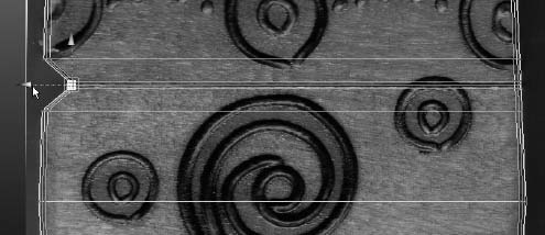
- In the Side view panel, move the bottom corner vertices on the cube to line up the bottom corners of the box to the reference image.
- In the Front view panel, move the bottom corner vertices to match the bottom of the box in the image (see Figure 3.48). Don't worry about the curvature in the middle of the box or the feet just yet. Save your work.
Figure 3.48 Taper the bottom of the cube.

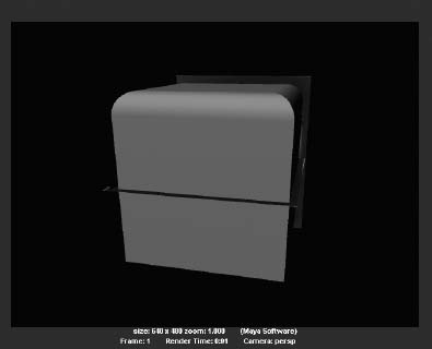
- Let's take a quick look at how this box will look rendered now. Click anywhere in the persp view panel to make it the active panel. In the Status line, click the Render The Current Frame icon, as shown in Figure 3.49.
Figure 3.49 Render a frame of the box from the Status line.

- Save your work. You can compare your progress to boxModel04.mb in the Scenes folder of the Decorative_Box project from the companion web page.
When you rendered your work in step 12, the Render view opened to show you a gray shaded box with the reference planes barely showing, as you can see in Figure 3.50.
Figure 3.50 The model thus far is rendered.
Status Line Explained
The Status line (see Figure 3.51) contains a number of important and often-used icons.
The Status line begins with a drop-down menu that gives you access to the menu sets in Maya. You'll notice immediately after the Menu Set drop-down menu, and intermittently throughout the Status line, white vertical line breaks with either a box or an arrow in the middle. Clicking a break opens or closes sections of the Status line.
Some of the most often used icons are identified here.

Scene File Icons
The tools in the first section of the Status line deal with file operations to start a new scene (![]() ), open an existing scene (
), open an existing scene (![]() ), or save your current scene (
), or save your current scene (![]() ).
).
Selection Modes
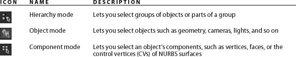
Selection modes allow you to select different levels of an object's hierarchy (see Table 3.7). For example, using a selection mode you can select an entire group of objects, only one of the objects in that group, or even points on the surface of that object, depending on the selection mode you're in.
Table 3.7 Selection modes
To switch between Object and Component mode, press the F8 key, which is Maya 2012's default hotkey. You may also select among the components and object mode from the marking menu when you right-click on an object.
Click the Hierarchy Mode icon to select the topmost node of a hierarchy or group of objects. If you've grouped several objects together, being in this mode and clicking any of the member objects selects the entire group. For more on hierarchies, see the section “Hierarchy and Maya Object Structure” in Chapter 2.
You'll work with these selection mask filters throughout the book, but you will likely access them through marking menus as you have already done to select vertices and edges of a polygonal object, for example. For a quick preview, hover your cursor over each of the icons to see a tooltip that gives the icon's name and describes its function. As you gain experience, you'll find these masks helpful in your workflow.
Snapping Functions, or Snaps
The icons with the magnets are called snaps. They allow you to snap your cursor or object to specific points in the scene. You can snap to other objects, to CVs or vertices (![]() ), and to grid intersections (
), and to grid intersections (![]() ) and other locations by toggling these icons. Therefore, you can place your objects or points precisely. You made good use of the snapping functions in the previous chapter in making the Solar System. Table 3.8 shows the various snaps.
) and other locations by toggling these icons. Therefore, you can place your objects or points precisely. You made good use of the snapping functions in the previous chapter in making the Solar System. Table 3.8 shows the various snaps.
Table 3.8 Snap icons

The Channel Box/Layer Editor Icons
These last three buttons on the Status line (Figure 3.52) toggle between the Attribute Editor and Channel Box view on the right side of the UI. Clicking the first icon (![]() ) shows or toggles the Attribute Editor, much the same as pressing Ctrl+A. The second icon (
) shows or toggles the Attribute Editor, much the same as pressing Ctrl+A. The second icon (![]() ) displays or hides the Tool Settings window along the left side of the UI, as you've seen with soft selections. The third icon here (
) displays or hides the Tool Settings window along the left side of the UI, as you've seen with soft selections. The third icon here (![]() ) toggles the display of the Channel Box, again much the same as pressing Ctrl+A.
) toggles the display of the Channel Box, again much the same as pressing Ctrl+A.
Figure 3.52 Attribute Editor/Channel Box/Tool Settings Icons.
![]()
Editing the Decorative Box Model Using the Shelf
Back to work on the box model. We will use the Shelf in the UI to access some of the commands for the next series of steps as we continue working on the box. The Shelf runs directly under the Status line and contains an assortment of tools and commands in separate tabs, as shown in Figure 3.53.
![]()
You can load the scene file boxModel04.mb in the Scenes folder of the Decorative_Box project from the companion web page, or continue with your own scene.
In the following steps, you have to add surface detail to the model so you can more adequately adjust its shape. We will examine these tools more thoroughly in Chapter 4. To edit the box to better fit the references, follow these steps:
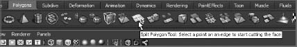
- Orient the persp view panel so you can see the bottom of the box and then select the box model. In the Shelf, click the Polygons tab. Click the Split Polygon tool icon as shown in Figure 3.54. The Split Polygon tool is also selectable through the menu Edit Mesh Split Polygon Tool.
Figure 3.54 The Split Polygon tool icon in the Shelf
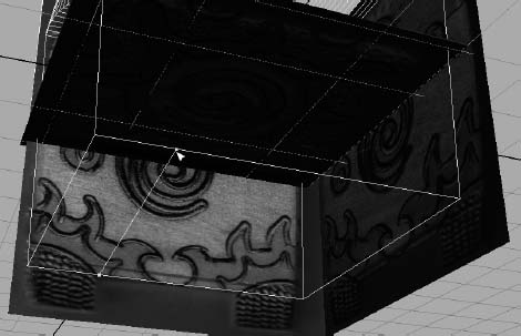
- Your cursor will change to a solid triangle and a text prompt will appear in the middle of your persp view panel asking you to “Click-drag on first edge.” Click, as shown in Figure 3.55, to select a point along the bottom left edge of the box that corresponds with where the box's feet begin.
Figure 3.55 Select the first point for the polygon split.

- Click a second point on the opposite edge on the bottom of the box to create a new edge line, as shown in Figure 3.56. Click the RMB to commit the new edge line. This creates surface detail along the bottom of the box for you to model the feet for the box. This methodology is explained in detail in Chapter 4.
Figure 3.56 Create a new edge line along the bottom of the box.
- Using the same procedures in steps 1 through 3, create three more edge lines for a total of four separate splits in the bottom face of the cube that line up with the legs of the box, as shown in Figure 3.57. The preceding four steps have created surface detail called faces that allow you to create the feet for the box.
Figure 3.57 Split the bottom face four times to create divisions for the box's feet.

- Press the Select tool icon in the Tool Box to the left of the UI (shown in Figure 3.58) to exit the Split Polygon tool. Your cursor returns to the regular Maya cursor.
Figure 3.58 The Select tool in the Tool Box

- Right-click on the box and select Face from the marking menu (Figure 3.59). As you hover your mouse over the parts of the box, the new faces in the four corners of the box you just created will highlight in red. Shift+click on the four corner faces to select all four faces, as shown in Figure 3.60.
- With the four faces selected, go into the Shelf and select the Extrude icon shown in Figure 3.61. This tool is also accessible through the menu Edit Mesh Extrude.
Figure 3.59 Select Face from the marking menu.
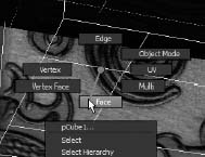
Figure 3.60 Select the four corner faces.

- Your Manipulator will change, as shown in Figure 3.62. Grab the Z-axis move handle and drag it down to “pull” the feet out of the bottom of the box as shown.
- By moving vertices, taper the feet to match the reference images in the Front and Side view panels; see Figure 3.63.
- Save your work. You can compare your progress to boxModel05.mb in the Scenes folder of the Decorative_Box project.
Figure 3.61 The Extrude icon in the Shelf.


Figure 3.63 Move the vertices on the feet to line them up to the reference images.

The Shelf and Tool Box Explained
Here is a brief explanation of the tools and icons in the Shelf and Tool Box.
The Shelf
The Shelf, shown earlier in Figure 3.53, is an area where you keep icons for tools. It's divided into tabs that define functions for the tool icons in the Shelf. Whenever you start Maya, the tab you used in your previous session of Maya will be selected and displayed.
Each tab is broken out into different function sets, showing you icons that are useful for a particular set of functions such as creating surfaces or creating lights and textures. You can change the Shelf display to show the functions you'll be using by clicking the tabs. The Custom tab is empty so that you can create your own custom Shelf, populating it with the tools you find most useful.
Don't worry too much about the Shelf right now; it may be better to use the commands from the menus first before turning to icons and shelves. Doing so will build your proficiency at finding the tools you need, and it will also give you the chance to explore further every time you open a menu.
The Tool Box
The Tool Box, shown in Figure 3.64, displays the most commonly used tools. You have been accessing these tools, such as Move or Rotate, primarily through their hotkeys. Table 3.9 lists the icons and their functions.
Table 3.9 Tool Box icons

In addition to the common commands, the Tool Box displays several choices for screen layouts that let you change the interface with a single click. This is convenient because different animations call for different view modes. Experiment with the layouts by clicking any of the six presets in the Tool Box.
![]()
Continuing the Decorative Box Model
Back to work! We'll be spending more time getting the box in shape. You can load the scene file boxModel05.mb in the Scenes folder of the Decorative_Box project, or continue with your own scene. In the following steps you will add more faces and edges to the model surface (a.k.a. mesh) so you can add detail to the shape.
- There is a little curve to the middle of the box. You will need to create a new edge line that runs across the middle of the box so you can bow out the sides in the middle. In the Layer Editor, toggle off visibility for the reference images by clicking the (
 ) icon for reference planes. Now you can see just the model of the box.
 - Select the box, and in the Polygons tab of the Shelf, click the Split Polygon tool icon (
 ). (This tool is also selectable through the menu Edit Mesh Split Polygon Tool.) You will be using the Help line located at the bottom of the UI for feedback for this tool to help you line up the new edge line you're about to create.
 - Move your cursor to the middle of one of the box's edges. Then click and drag the point to the middle of that edge as shown in Figure 3.65, but do not release the mouse button just yet. Notice in the lower-left corner of the UI is a feedback readout that gives you a percentage (Figure 3.66). Drag the mouse up and down the box's edge and notice the percentage readout in the Status line. You can see when the Split Polygon tool snaps at 50%. Release the mouse at 50% and that will place the point in the middle of that edge.
- Use the percentage feedback in the Help line to place Split Polygon points at 50% for the remaining three edges of the box to create a horizontal split line in the middle of the box, as shown in Figure 3.67. When you place your last point where you started, right-click to commit the action.
Figure 3.65 Click and drag the Split Polygon tool on this edge of the box, and place the point at 50%.

Figure 3.66 The Help line gives you the percentage feedback for the Split Polygon tool.

Figure 3.67 Create an edge line all the way around the box.

- Press the Select tool icon in the Tool Box to the left of the UI (
 ) to exit the Split Polygon tool. Your cursor returns to the regular Maya cursor. Turn on the referencePlanes layer to show the image references.
 - Right-click on the box and choose Vertex from the marking menu. Move the new vertices in the middle of the box to bow out the box slightly. Move the rest of the vertices to match the model to the box images in the Side and Front view panels (see Figure 3.68).
- Save your work. You can compare your progress to boxModel06.mb in the Scenes folder of the Decorative_Box project.
Time Slider and Help Line Explained
As you just saw, using the tool's feedback helped you position your edge lines properly for the box. In this section, we will examine the bottom part of the UI where the Status line lives.
Figure 3.68 Adjust the cube to fit the reference images.

Time Slider/Range Slider
Running horizontally across the bottom of the screen are the Time slider and the Range slider, as shown in Figure 3.69. The Time slider displays the range of frames available in your animation and gives you a gray bar, known as the Current Time indicator. You can click it and then drag it back and forth in a scrubbing motion to move through time in your sequence. (When instructed in this book to scrub to a certain point in your animation, use this indicator to do so.)
Figure 3.69 The Time and Range sliders

The text box to the right of the Time slider gives you your current frame, but you can also use the text box to enter the frame you want to access. Immediately next to the current time readout is a set of DVD/DVR-type playback controls that you can use to play back your animation.
Below the Time slider is the Range slider, which you use to adjust the range of animation playback for your Time slider. The text boxes on either side of this slider give you readouts for the start and end frames of the scene and of the range selected.
You can adjust any of these settings by typing in these text boxes or by lengthening or shortening the slider with the handles on either end of the bar. When you change the range, you change only the viewable frame range of the scene; you don't adjust any of the animation.
This lets you zoom into sections of the timeline, which makes adjusting keyframes and timing much easier, especially in long animations. When you zoom into a particular section of your time frame, the Time slider displays only the frames and keyframes for that portion, making it easier to read.
Command Line/Help Line
Maya Embedded Language (MEL) is the user-accessible programming language of Maya. Every action you take invokes a MEL command or script that runs that particular function. You can write your own commands or scripts using either the Command line or the Script Editor. Use the Command line (see Figure 3.70) to enter single MEL commands directly from the keyboard in the white text box portion of the bar.
Figure 3.70 The Command line and the Help line

Below the Command line is the Help line. This bar provides a quick reference for almost everything on the screen. For the most part, it's a readout of functions when you point to icons. It also prompts you for the next step in a particular function or the next required input for a task's completion.
The Help line is very useful when you're not really sure about the next step in a command, such as which object to select next or which key to press to execute the command. You'll be surprised by how much you'll learn about tool functions by reading the prompts displayed here.
Finishing the Decorative Box Model
Now that you have the overall shape of the box finished, you need to add a few finishing details to the box. You will round out the edges of the box so they are not sharp, as well as add a line around the top of the box for the lid's seam and hinges. You can load the scene file boxModel06.mb in the Scenes folder of the Decorative_Box project, or continue with your own scene.
When you build a model in CG, all the corners and edges will be sharp. To make a model more dynamic, you can round or bevel the edges to heighten the realism of the model when it is lit and rendered.
Figure 3.71 Hiding objects using the Outliner
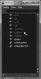
- Let's turn off the image reference planes again, but this time, let's do it a different way. Open the Outliner window by choosing Window Outliner. You are already somewhat familiar with the Outliner from the Solar System exercise in the previous chapter. Select frontPlane, sidePlane, and topPlane in the Outliner, and hide them by selecting Display Hide Hide Selection or by pressing Ctrl+H. This way, you can individually hide any object in your scene. Notice that when an object is hidden, its Outliner entry is grayed out (Figure 3.71).
- Select the box and open the Attribute Editor. Under the Object Display Drawing Overrides headings, uncheck the Enable Overrides box, as shown in Figure 3.72, to display the box in Shaded mode again. This will help you see how the bevel works.
- We will bevel the edges of the box throughout to soften the crisp corners of the cube that the real box doesn't have. Right-click on the box and choose Edge from the marking menu. Shift+select all the outer edges of the cube, as shown in Figure 3.73.
- With those edges selected, select Edit Mesh Bevel . Set everything to the defaults, but change Segments from 1 to 3. Click Bevel, and your box should resemble the one shown in Figure 3.74.
- Select the cube, and delete its history by selecting Edit Delete By Type History. This process essentially cleans up the model and the procedures it has undergone. You'll learn about History in the following chapters.
- You have one final detail to tend to on the lid. You need to add the hinge area you can see in the Side view panel's reference image. Select the reference planes in the Outliner (pPlane1, pPlane2, and pPlane3), and press Shift+H to unhide them (you can also choose Display Show Show Selection). Make sure you're in Texture Shaded mode in your views (press 6) to see the box images.
- Select the box. Turn its display back to wireframe by going into the Attribute Editor and, in the pCubeShape1 tab, turning on Enable Overrides under the Object Display Drawing Overrides heading.
Figure 3.72 Turn off Drawing Overrides in the Attribute Editor to display the box in Shaded mode again.
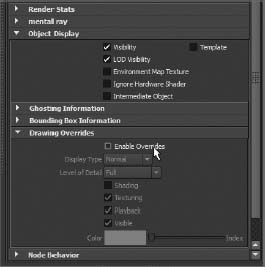
Figure 3.73 Select all of these edges for beveling.
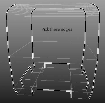
Figure 3.74 The beveled edges of the box

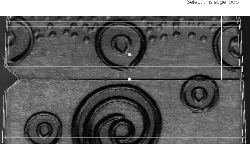
- Select Edit Mesh Insert Edge Loop Tool. This tool is like the Split Polygon tool in that it inserts new edges into a model. Your cursor will change to the solid triangle again. Click on the upper edge of the box and drag a dashed line to line up with the lid's seam in the box reference images, as shown in Figure 3.75. Once placed and you release the mouse button, the edge line will be completed and the dashed line will turn solid.
Figure 3.75 Insert an edge loop to line up with the seam in the real box.
- In the Side view panel, insert four more horizontal edge loops for a total of five edge loops, as shown in Figure 3.76. This gives you edges with which to create the wedge cutout where the box is hinged, and that gives you a little indentation where the lid meets the box. You won't create a separate lid because you won't animate the box to open or close, and you don't need to see the inside.
Figure 3.76 Insert these five edge loops for the lid of the box.

- In the Side view panel, select the appropriate vertices (see Figure 3.77), and move them to create the wedge-shaped indentation as shown.
Figure 3.77 Move the vertices to create the hinge area in the back of the box.
- Choose Select Select Edge Loop Tool. Select the middle edge loop you created earlier for the indent where the lid meets the box, as shown in Figure 3.78. Press R to scale the edge loop very slightly inward as shown.
Figure 3.78 Select this edge loop, and scale it to create an indent line where the lid meets the box.
- Hide the reference planes again through the Layer Editor, and turn Shading back on for the cube in the Attribute Editor. Figure 3.79 shows the completed box. But there's still a little snag. Notice the dark area where the lid meets the box, where you just created the slightly indented seam line. This is due to Normals. It makes the lid look as if it's angled inward.
- Select the box, and choose Normals Set Normal Angle. In the Set Normal Angle window that pops open, set the Angle to the default of 30, and click Apply And Close. Doing so fixes the darkening, as shown in Figure 3.80. For more on Normals, see the note in this section. Select the box, and delete its history by choosing Edit Delete By Type History.
- Save your work, grab someone you love, and give them a hug.
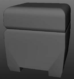
Figure 3.80 The box now looks right.

You're finished with the modeling portion of this decorative box, and gotten to know the interface much better. In later chapters, you'll texture, light, and render the box with photorealism in mind. You can load boxModel07.mb from the Scenes folder in the Decorative_Box project to compare your work.
NORMALS
Normals are imaginary lines that are perpendicular to a mesh's poly face and that define sides for that face. They also help determine how a renderer, such as mental ray, shades the surface. In some cases when you're modeling, you may notice an action that causes part of your model to display a darkened area as you see in the decorative box in Figure 3.79. By manually setting a Normal angle for the box as you did in step 13 of the exercise, you override the seeming display error. You'll learn more about Normals in Chapter 7.
The Attribute Editor and Outliner Explained
You have worked with the Attribute Editor and Outliner several times already. Here's a brief overview of these all important windows in Maya's workflow.
The Attribute Editor Window
To use the Attribute Editor, select Window ![]() Attribute Editor (Ctrl+A). The Attribute Editor window is arguably the most important window in Maya. Every object is defined by a series of attributes, and you edit these attributes using the Attribute Editor. This window displays every attribute of an object, and you can use it to change them, set keyframes, connect to other attributes, attach expressions, or simply view the attributes.
Attribute Editor (Ctrl+A). The Attribute Editor window is arguably the most important window in Maya. Every object is defined by a series of attributes, and you edit these attributes using the Attribute Editor. This window displays every attribute of an object, and you can use it to change them, set keyframes, connect to other attributes, attach expressions, or simply view the attributes.
The Attribute Editor has tabs that correspond to the object's node structure. You've learn a little about Maya's object structure in the previous chapter. As you can see, each tab displays different attributes of the object.
Try This In a new scene, create a NURBS sphere with Interactive Creation turned off (Create ![]() NURBS Primitives
NURBS Primitives ![]() Sphere). Select the sphere, press Ctrl+A to open the Attribute Editor, and click the makeNurbSphere1 tab. Grab the top of the Attribute Editor if it is docked to the UI, and drag it off to the right to undock it. This will automatically display the Channel Box, as shown in Figure 3.81.
Sphere). Select the sphere, press Ctrl+A to open the Attribute Editor, and click the makeNurbSphere1 tab. Grab the top of the Attribute Editor if it is docked to the UI, and drag it off to the right to undock it. This will automatically display the Channel Box, as shown in Figure 3.81.
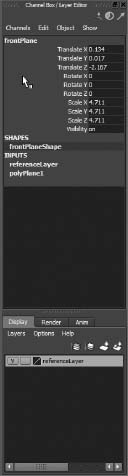
You'll notice that the Channel Box has the primary attributes (Translate X, Translate Y, Translate Z, Rotate X, and so on) of the sphere listed. Below them, you'll find the shapes node named nurbsSphereShape1 and the inputs node makeNurbSphere1 listed. If you click the makeNurbSphere1 entry in the Channel Box, it will expand to show you Select attributes from the tab of the same name in the Attribute Editor. These attributes, despite being shown in two places, are the same. If you edit one in the Channel Box, it will be reflected in the Attribute Editor, and vice versa. The Channel Box is essentially a quick reference, giving you access to the most likely animated attributes of an object. The Attribute Editor goes into detail, giving you access to everything that makes up that object and the other nodes that influence it.
Figure 3.81 The Attribute Editor is undocked and the Channel Box appears again.

Try changing some of the settings in this window and see how doing so affects the sphere in the view panels. For example, changing the Radius attribute under the nurbsSphereShape1 tab changes the size of the sphere. Click the nurbsSphere1 tab next, and you'll see the primary attributes listed. Try entering some different values for the Translate or Scale attributes to see what happens to the sphere in the view panels.
Figure 3.82 You can keep notes with an object's attributes in the Attribute Editor.

On the flip side, press W to activate the Move tool, and move the sphere around one of the view planes. Notice that the respective Translate attributes update in almost real time in both the Attribute Editor and the Channel Box. You'll see an area for writing notes at the bottom of the Attribute Editor. This is handy because you can put reminders here of important events, such as how you set up an object or even a birthday or an anniversary. If you drag the horizontal bar, you can adjust the size of the notes space, as shown in Figure 3.82.
Because you'll use the Attribute Editor constantly, you may want to keep the window open all the time and just move it around. You can also press the Ctrl+A hotkey to open the window more easily.
The Outliner
When you're well into an animation or a complex model, you'll invariably have several elements in your scene. Without a roadmap, finding the correct object to select or manipulate can be difficult. Using the Outliner, as you have already, greatly increases your efficiency. The Outliner is perfect for organizing, grouping objects, renaming nodes, and so forth, as you've already seen.
To use the Outliner, select Window ![]() Outliner (see Figure 3.83). It displays all the objects in your scene as an outline. You can select any object in a scene by clicking its name.
Outliner (see Figure 3.83). It displays all the objects in your scene as an outline. You can select any object in a scene by clicking its name.

The objects are listed by order of creation within the scene, but you can easily reorganize them by MMB+clicking and dragging an object to a new location in the window; doing so lets you group certain objects in the list. This is a fantastic way to keep your scene organized.
Additionally, you can easily rename an object by double-clicking its Outliner entry and typing a new name. It's crucial to an efficient animation process to keep things well named and properly organized. By doing so, you can quickly identify parts of your scene for later editing and troubleshooting.
A separator bar in the Outliner lets you split the display into two separate outline views. By clicking and dragging this bar up or down, you can see either end of a long list, with both ends having independent scrolling control.
Summary
In this chapter, you learned more about the user interface and the primary windows used in Maya as you worked on modeling the decorative box. The user interface combines mouse and keyboard input as well as plenty of menu and tool icons that you can select and use to accomplish your tasks. It also gives you a host of options to customize Maya to suit your needs.
You'll be quizzed in 10 minutes. Do you have it all memorized? Don't worry if you haven't absorbed all the information in this chapter. Now that you've had some exposure to the Maya user interface, you'll be familiar with the various windows when you really get to work.
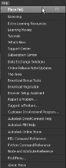
You can always come back to this chapter to refresh your memory. Remember, you should learn the Maya program using its default settings. When in doubt, remember to access the Maya Help system, as shown in Figure 3.84.
Figure 3.84 The best menu... ever!
To start, concentrate on using the menus to access most commands. After you're comfortable working in Maya, you can begin using hotkeys and shortcuts, and eventually you may even customize them. At this stage, though, focus on getting a clear understanding of the tools and what they do. You'll be introduced to various hotkeys and shortcuts as you work through the exercises in this book.