
According to the AIA document E202 BIM Protocol Exhibit, there are five levels of model development ranging from 100 to 500. If you examine excerpts from the Model Content Requirements describing each level of development (LOD) for the design professions—LOD 100, LOD 200, and LOD 300—the evolution of modeling granularity becomes apparent. Although LOD 100 represents a conceptual level of information defined as "overall building massing," LOD 200 and LOD 300 are represented by "generalized systems or assemblies" and "specific assemblies," respectively. This chapter will help you create walls that comply with both LOD 200 and LOD 300.
Walls in Revit can be created in four different ways: basic walls, stacked walls, curtain walls, and in-place walls. In this chapter, you'll explore the skills you'll need to create and customize walls to meet the needs of your design. You will also dive into the new and exciting realm of complex curtain wall and panel generation made possible with Revit's conceptual massing tools.
In this chapter, you'll learn to:
Use extended modeling techniques for basic walls
Create stacked walls
Create simple curtain walls
Create complex curtain walls
As you might already know, walls in Revit are made from layers of materials that can represent generic placeholders for design layouts to complete assemblies representative of actual construction. These layers are assigned functions that allow them to react to similar layers in other walls as well as in floors and roofs. The function assignments within object assemblies give you a predictable graphic representation when you join these types of overlapping elements.
After you have become familiar with the basic modeling functions for walls, you'll probably need to create your own wall types to achieve more complex designs. As you also add more information into the source of your building model, you will be able to extract more useful results through intelligent tagging and schedules. In this section we'll show you how to get the most out of your basic wall types in Revit.
Walls and curtain walls are system families in Revit, which means they exist in a project but cannot be saved as individual families (RFA files). Other system families in Revit include floors, ceilings, roofs, stairs, railings, and mullions. There are only three ways to create or add new system families to your project:
Duplicate a type from one that already exists and modify its properties
Copy and paste them in as objects from one project to another
Use the Transfer Project Standards tool
In Chapter 4 we discussed different strategies for managing standard content through the use of templates. If you have a series of standard wall types you use on every project, you have the option of either storing such wall types in your main project template using the subtractive method or storing them in separate container project files in an additive method. If you need to make new, custom types that are not part of your template, you can create new wall types on the fly at any stage of a project by duplicating existing types, adding or removing wall layers, and adjusting the parameters to meet your requirements. Regardless of which method you employ to manage templates and standard system families, we will show you how to create and customize your own wall types in the following sections.
Note
Within a project file, you can access and edit a wall type in one of two ways:
In the Project Browser, scroll down to the Families category, locate any wall type, right-click it, and select Properties, or simply double-click the wall type name.
Select a wall in the model or start the Wall command, open the Properties Palette, and click Edit Type.
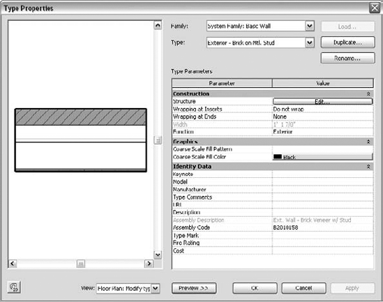
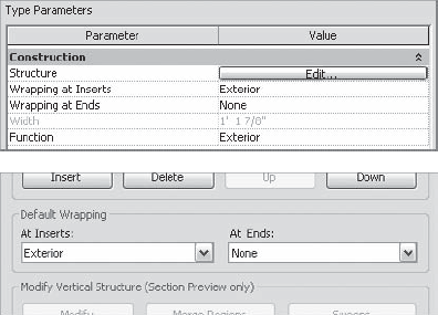
The Type Properties dialog box will appear as shown in Figure 13.1. If you don't see the graphic preview to the left, click the Preview button at the bottom of the dialog box.
Note
The first aspect we will discuss is the editing of a wall type's structure. To access these settings, select Structure as the parameter to edit. This will open the Edit Assembly dialog box, as shown in Figure 13.2. From here you can add or delete wall layers, define their materials, move layers in and out of the core boundaries, and assign functions to each layer. You can also add sweeps and reveals or modify the vertical constraints of the layers.

This dialog box is divided into four zones: the Preview window, the Layers table, the Default Wrapping option, and the Modify Vertical Structure options (which are active only when the preview is set to section display).
- Preview Window
On the left side of the dialog box, you will see a graphic preview of the wall structure in plan or section. If you didn't activate it in the Type Properties dialog box, click the Preview button at the bottom of the dialog box. To switch from the default plan view to the section view or vice versa, click the drop-down list under View to choose an alternate viewing option. In the preview, the core boundaries of the wall are shown with green lines. Note that in the section preview, each wall layer is highlighted in blue when you select a row in the Layers table. Also note that you can change the height of the wall shown in the section preview by modifying the Sample Height value in the upper-right part of the dialog box. You can use any mouse-based navigation method to adjust the preview as well as activate the Steering Wheel by clicking the button at the bottom right of the dialog box.
- Layers Table
The Layers table is where you add, delete, move, and define layers of the wall structure. Each wall layer is represented as a separate row of information. Two of the rows are gray, representing the core boundaries of the wall (which will be discussed in greater detail later in the "Wall Core" section of this chapter). The table is divided into four columns:
- Function
This column provides six choices for wall layer functions that relate to the purpose of the material in the assembly. Each of these functions defines a priority that determines how it joins with other walls, floors, and roofs. Note that the numeric priority is more important to understand than the name of the function itself.
Structure [1] defines the structural components of the wall that should support the rest of the wall layers. This function gives the highest priority to a wall layer and allows it to join with other structural layers by cutting through lower-priority layers.
Substrate [2] defines continuous board materials such as plywood, particle, or gypsum board.
Thermal/Air [3] defines the wall's thermal insulation layer and/or an air gap.
The Membrane Layer is a zero-thickness material usually represents vapor prevention.
Finish 1 [4] specifies a finish layer to use if you have only one layer of finish.
Finish 2 [5] specifies a secondary, weaker finish layer.
With the exception of the Membrane Layer, which has no priority assigned, all the other layers have a priority value from 1 to 5. Revit uses these priorities to determine how to clean up the intersections between various layers when two or more walls are joined. The principle is simply explained: priority 1 is the highest and 5 is the lowest. A layer that has a priority of 1 will cut through any other layer with a lower priority (2, 3, 4, or 5). A layer with priority 2 will cut through layers with priority 3, 4, or 5, and so on. In Figure 13.3, layers with the same priority clean up when the two intersecting walls are joined. Notice the way the finish layers don't join on the right side of the vertical wall because one has a priority 4 and the other is priority 5.
- Material
Associating a material to a wall layer provides graphic (color, cut/surface patterns, and render appearance), identity (mark, keynote, description, and so on) and physical characteristics (for analysis purposes) for each wall layer. Using material takeoffs, you can calculate quantities of individual materials used in wall assemblies throughout your project. Keynoting and material tagging functionality is also supported through wall layers and is discussed in greater detail in Chapter 19, "Annotating Your Design."
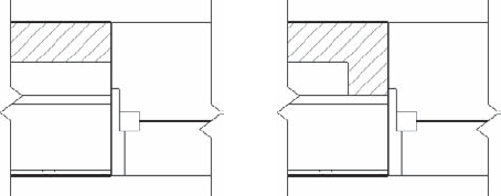
A material definition also affects cleanup between layers of joined walls. If the priority of the layers is the same and the material is the same, Revit cleans up the join between these two layers. If the priority of the layers is the same but the materials are different, Revit separates the two layers graphically with a thin line. In Figure 13.4 the structure layer of one of the joined walls was simply changed from
Metal - Stud LayertoMetal - Stud Layer 2.- Thickness
This value represents the actual thickness of the material. Note that the membrane layer is the only layer that can have a thickness of zero.
- Wraps
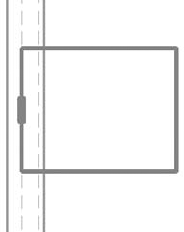
Wall layers rarely end with exposed edges at wall ends or wall openings, windows, or doors. This option allows a layer to wrap around other layers when an opening or wall end is encountered. Figure 13.5 illustrates the layer wrapping of the outer wall layer based on the closure plane defined in the window family. Layer wrapping will be covered in greater detail later in this chapter.
- Default Wrapping
Although you can specify whether each wall layer will wrap in the Layers table, you must also specify whether these options are activated at all in the wall type. To activate this option, you must decide whether the wrapping should occur at openings or wall ends or both. For inserts, you can choose Do Not Wrap, Exterior, Interior, or Both. Similarly, for wall ends the options are None, Exterior, and Interior. The default wrapping parameters appear in both the Edit Assembly dialog box and the wall's Type Properties dialog box.
- Modify Vertical Structure
These settings are available only when you enable the section view in the Preview window. In this area of the Edit Assembly dialog box, you can add articulation to the wall type using any combination of cornices, reveals, trims and panels. We will discuss these in the "Adding Wall Articulation" section later in this chapter.

In summary, editing a wall type's structure begins with adding or deleting wall layers. Each layer is assigned a priority, material, thickness, and wrapping option. To move layers up and down in the table or to add and remove layers, use the buttons at the bottom of the Layers table. Next we will cover some more complex aspects of wall structure in greater detail: wall cores, function, and layer wrapping.
One of the unique functions of a basic wall in Revit is its ability to identify a core. The wall core is more than a layer of material; in fact, it can comprise several material layers. It defines the structural part of the wall and influences the behavior of the wall and how it interacts with other elements in the model. The core boundaries are references to which you can dimension or constrain sketch lines when you use the Pick Walls selection option for floors, ceilings, or roofs.
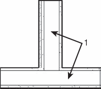
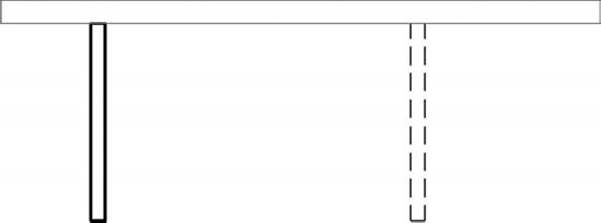
The example shown in Figure 13.6 illustrates a sample floor in Sketch mode where the outer core boundary of the wall was selected using the Pick Walls method. Note that the core boundaries of the wall are shown as dashed lines for clarity.
When floors generated with the Pick Walls method intersect the walls that were picked during Sketch mode, you will receive a prompt to automatically join the geometry and cut the overlapping volume out of the wall:
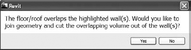
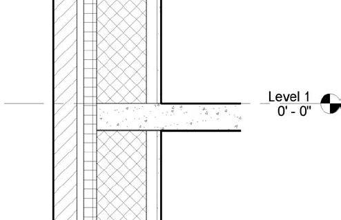
If you click Yes to this message and examine the intersection of the wall and floor in a section view, you will see the result of the joined elements (Figure 13.7). Note that you can get the joining prompt to appear again simply by selecting the floor, clicking the Edit Boundary button in the ribbon, and then clicking Finish Edit Mode (green check icon). If any portion of the selected floor and related walls still overlap but are not joined, the prompt will be displayed.
The Function type property of walls is a simple list of values, but it can be used in very powerful ways. A wall's function can be used to filter schedules or as view filters—for example, if you wanted to hide interior walls for a series of drawings only showing core and shell (exterior) elements. The function property also affects the default placement behavior when you create new walls. The behaviors associated with each function are as follows:
Interior (default height for new walls is set to the level above the active level)
Exterior (default height is Unconnected: 20'-0" [8000mm])
Foundation (default height is determined as Depth, specified down from the active level)
Retaining (default height is Unconnected: 6'-0" [2000mm])
Soffit (default height is Unconnected: 1'-0" [250mm])
Core-shaft
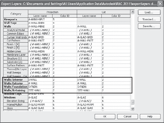
The Function type property can also be used when exporting from Revit to CAD formats. You can export walls of different functions to specific layers assigned in the Export Layers dialog box shown in Figure 13.8.
To create a layer wrapping solution for openings that reflect real-world conditions, you must define two settings. First, select the layer(s) of the wall structure you want to wrap and check the boxes in the Wraps column of the Edit Assembly dialog box. You must then specify the default wrapping behavior for the wall type. These default settings can be set in either the Edit Assembly or Type Properties dialog box, as shown in Figure 13.9.
Specifying the layer wrap settings in the wall type alone may not be sufficient to generate the graphic results you desire. Another set of rules established in hosted families allows you to further customize how layers in a wall will wrap to inserted objects. The following exercise will illustrate this functionality.
Begin by opening the file c13-Wall-Wrapping.rvt from this book's web page: www.sybex.com/go/masteringrevit2011. Activate the Level 1 floor plan, and you should see a wall with an inserted window as shown here:

To begin the exercise, select the wall, open the Properties Palette, and click Edit Type. Notice the setting for Wrapping At Inserts is set to Do Not Wrap and the setting for Wrapping At Ends is set to None.
Click OK to close the Type Properties dialog box.
Select the inserted window and click Edit Family on the Modify | Windows tab in the ribbon.
When the window family opens, go to the Project Browser and activate the floor plan named Floor Line.
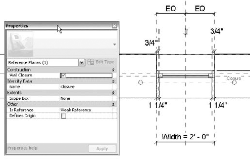
You will notice that this window family has been slightly modified from the original Fixed window family in Revit's default library. Two reference planes have been added that allow the depth of the window frame and the wall wrapping to be customized.
Find the reference plane named Closure, select it, and open the Properties Palette. Find the parameter named Wall Closure and make sure the option is checked, as shown in Figure 13.10.
Create a dimension between the exterior face of the sample wall and the Closure reference plane. Note that you may need to use the Tab key to ensure you have selected the wall reference and not the centerline of the wall or any other extraneous reference plane.
Click the Esc key or the Modify button to exit the dimension command and select the dimension you just created.
On the Options Bar, find the Label drop-down list and choose <Add Parameter...>.
In the Parameter Properties dialog box, type Exterior Wall Closure in the Name field and click OK to close the dialog box.
Click Load Into Project from the Family Editor panel in the ribbon. Note that you may be prompted to select a project or family if you have more than the two sample files open. When prompted with the Family Already Exists dialog box, select Overwrite The Existing Version.
In the Level 1 floor plan of the example project, select the wall and click Edit Type from the Properties Palette. From the Structure parameter, click Edit.
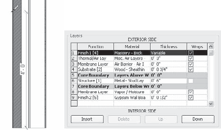
In the Edit Assembly dialog box, find row 1, which will have a function of Finish 1 [4], and the material Masonry - Brick. Make sure the Wraps option is checked.
Set the Wrapping At Inserts option to Exterior and click OK to close both dialog boxes.
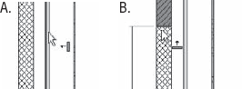
You should now see the masonry layer wrapping into the opening in the wall created by the inserted window. You can now customize the depth at which the brick will wrap.
Select the window and click Edit Type from the Properties Palette. Find the Exterior Wall Closure parameter and change the value to 0'-65⅝".
Click OK to close the Type Properties dialog box. Notice how the depth of the wrapped masonry layer changes in the plan view:

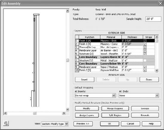
If you need to develop more complex and articulated finishes expressed horizontally along the vertical surfaces of certain walls, you can customize wall types in a variety of ways within Revit to achieve just about any aesthetic effect. Reveals and sweeps can be added to a wall type, and you can edit the vertical extents of material layers. You can find a good example of this kind of wall in the default project template. The wall type Exterior - Brick and CMU on MTL. Stud (Figure 13.11) contains a variety of sweeps, reveals, and vertical modification of material layers.

To access these settings, select any wall in your project and click Edit Type in the Properties Palette. You can also find the wall type in the Project Browser and double-click it to open the Type Properties dialog box. Once it is open, make sure the preview pane is open and the view in the preview is set to Section. Within the Type Parameters, click the Edit button in the Structure field to open the Edit Assembly dialog box and begin modifying the layers and vertical articulation of the wall type, as shown in Figure 13.12.
In the following sections, we'll examine how to create these types of articulation in your wall type. To begin the exercises, create a new project using Revit's default.rte or DefaultMetric.rte template. Create a single wall segment using the type Exterior – Brick On Mtl. Stud. You will create a new wall type based on this wall throughout the following exercises.
We will begin our series of exercises by creating a new wall type based on an existing layered wall structure. Select the wall segment you created using the type Exterior – Brick On Mtl. Stud and open the Type Properties dialog box. Click the Duplicate button and create a new wall type named Mastering - Wall Exercise.
Now let's assume that you need to create a partial region of the finish face where the material is different. For example, you might want to use split-face concrete block at the base of the wall instead of brick.
With the Type Properties dialog box open, click the Edit button in the Structure field to open the Edit Assembly dialog box. Make sure the preview window is open and the view is set to Section.
In the upper right of the Edit Assembly dialog box, change the Sample Height value to 6'-0" [2000mm]. Use either the Steering Wheel button at the lower left of the dialog box or your mouse to zoom into the shorter segment of wall in the preview window.
Click the Split Region button under Modify Vertical Structure and move your mouse pointer along the inside face of the brick layer to a point 4'-0" [1200mm] above the bottom of the sample as shown in Figure 13.13. Note that when you split the layer, the thickness value of the layer indicates it is Variable.
Click the Insert button to add another row immediately below the first exterior layer. Change its function to Finish 1, its material to Masonry - Split Face Block, and its thickness to 0'-0".
Click the Assign Layer button, select the new row you created in the previous step, and then click the lower portion of the split region in the section preview.
Click OK to close all open dialog boxes and save your project for additional exercises in this chapter.
After you assign a material row to a split layer, you'll notice that the thickness values of the two layers are linked but you can't change them in the table. To change the thickness of a split wall layer, click the Modify button and select one of the faces in the section preview. Edit the temporary dimensions to change the thickness of the layer.
You may also notice that once a layer is split and an additional layer is assigned to the split portion, the resulting portions can only be the same thickness. To create a similar result with a layer of varying thickness, you will need to create a stacked wall. We will discuss this later in "Creating Stacked Walls."
If you encounter a situation where you need to merge horizontal or vertical layers that already exist in a wall type, use the Merge Regions button and select a line in the section preview between two layers. Once the mouse pointer is over a line between two layers, an arrow indicating which layer will override the other appears as shown in Figure 13.14.
Many walls have horizontal articulations that are either attached to or embedded in the wall assembly. Cornices, soldier courses, and reveals are examples of elements that can be incorporated into wall types in Revit. To begin adding these, we will continue our previous exercise of creating a new wall type named Mastering - Wall Exercise. In the following exercise, you will add a bullnose sweep to the wall.
Return to the wall's type properties and open the Edit Assembly dialog box.
Click the Sweeps button to open the Wall Sweeps dialog box. Click the Load Profile button and open the file
c13-Profile-Bullnose.rfa, which can be downloaded from this book's companion web page (www.sybex.com/go/masteringrevit2011).Click the Add button to insert a sweep row. Change the values in the row as follows:
Profile: c13-Profile-Bullnose: 3⅝" D x 4" H
Material: Concrete - Precast Concrete
Distance: 4'-0" [1200mm]
From: Base
Side: Exterior
Cuts Wall: Checked
Cuttable: Checked
Click Apply and you should see the sweep appear just above the split region, as shown in Figure 13.15.
Notice that the loaded profile was created for predictable results when placed in a wall assembly. For your own wall you may need to adjust the offset, flip, and setback values to achieve the desired results. Next, you'll add a different profile to the same assembly.
Click OK to close the Wall Sweeps dialog box. In the Edit Assembly dialog box, change the Sample Height value to 12'-0" so that the next sweep addition won't conflict with the one you just added. Adjust the section view as required to see the whole wall.
Click Sweeps to reopen the Wall Sweeps dialog box. Click Load Profile again and navigate to Revit's default library. From the Profiles folder, select either
Cornice-Precast.rfaorM_Cornice-Precast.rfa.Click Add to create another new row and change the values in the row as follows:
Profile: Cornice-Precast
Material: Concrete - Precast Concrete
Distance: 0′-0″
From: Top
Side: Exterior
Offset: −0′-3 5/8″
Notice that the order of the rows is automatically adjusted based on the vertical relationship of the sweeps added to the wall. Click OK to close the Wall Sweeps dialog box.
Notice that a negative value for Offset was specified to bring the cornice sweep into the exterior finish layer. Vertical adjustments can be made by assigning positive or negative values in the Distance column.
Click OK to close all open dialog boxes and save the project file for additional exercises in this chapter.

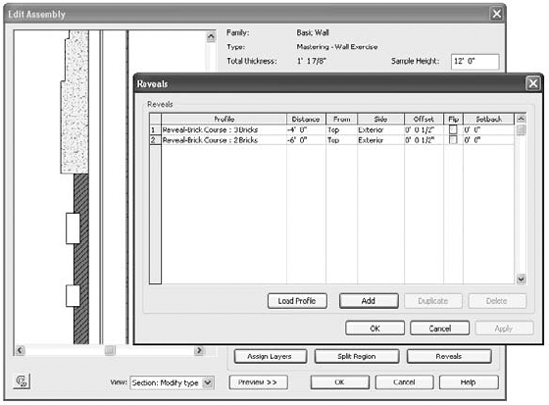
The process to create reveals is almost identical to that used to create sweeps. Simply click the Reveals button to open the Reveals dialog box. Experiment with adding your own reveals to the wall type you're creating throughout this chapter's exercises. We've added two reveals to the wall assembly (Figure 13.16) using the default Reveal-Brick Course profile family.
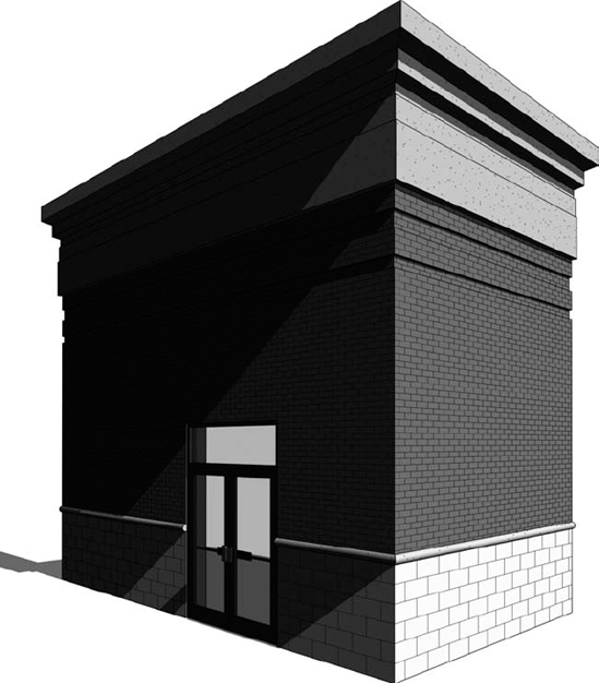
If you create two or more walls using your new compound wall type, you'll see how nicely the sweeps wrap around corners in a 3D or camera view, as shown in Figure 13.17.
In the previous exercises, you learned how to include sweeps and reveals in the assembly of a wall type; however, you can also apply a sweep to a wall if it's only needed in a limited location. For example, you might need to create a fancy wainscot molding in one special room. To accomplish this, go to the Home tab in the ribbon and click Wall and then Wall Sweep. Note that a sweep can be placed on a wall vertically or horizontally by changing the placement option in the ribbon while the Wall Sweep tool is active. Select a wall sweep type from the Properties Palette and pick the wall faces to which you'd like to apply the sweep. If necessary, the sweep can be adjusted vertically in an elevation or section view.
Although profile families can be used in them, a wall sweep is a system family that only exists in a Revit project. New sweep types can only be created by using the Transfer Project Standards tool or by duplicating existing types within your active project. You can now also schedule wall sweeps in Revit 2011.
Let's take a look at how to customize the returns of a wall sweep:
Select the sweep and it will display grips at each end. You can simply drag either end of the sweep as required.
To change the way the sweep returns or turns a corner, click the Modify Returns button in the Modify | Wall Sweeps contextual ribbon. Notice that there are some additional settings in the Options Bar.

You can change the angle of the return or return it to a straight cut, but for now leave the options as Return and Angle = 90°.
The mouse pointer changes to a knife symbol, and when you click somewhere on the end of the sweep, it creates a new segment that can be wrapped around the edge of a wall or opening.
After picking one of the ends of the sweep, press Esc or use the Modify tool to exit the command.
Select the sweep again and drag the control to adjust the length of the sweep return around the corner of the wall. Figure 13.18 shows how the return can be wrapped around the edge of a wall.

In the previous sections, we explored different methods to create a variety of basic wall types. When you begin to use these types to assemble your building model, there are still more methods at your disposal to further customize how walls are applied. Let's take a look at some techniques you can use for modeling basic walls. Note that some of these techniques can be used for stacked walls and curtain wall as well.
In many types of construction, you'll need layers of materials to extend within or beyond the constraints of the wall. Some common examples include the extension of sheathing and siding on an exterior wall or gypsum wallboard extending only slightly above the ceiling for interior partitions (Figure 13.19).

Enabling the extension of layers within a wall assembly requires you to unlock specific edges in the section preview of the Edit Assembly dialog box. Once layers have been unlocked, an instance parameter of the wall becomes active; either Base Extension Distance or Top Extension Distance (depending on which edges you unlocked). This value can be entered directly in the Properties Palette or adjusted graphically in a section view by dragging the small blue triangle control at the edge of the unlocked layer. Let's go through an exercise to explore this functionality:
From the Home tab of the ribbon, select the Wall tool to create a new wall using any generic type. Select it and duplicate it by editing the type. Name the new type Exterior Siding.
Click Edit in the Structure field to open the Edit Assembly dialog box.
Add a new layer to the exterior of the wall, set its function to Finish (4), use the material Siding - Clapboard, and assign a thickness of ¾" [18mm].
Open the preview pane and switch to section view. Zoom into the bottom of the wall.
Select the Modify button and click the bottom edge of the exterior siding layer. Click the padlock icon to unlock the layer (Figure 13.20). Note that you can unlock as many layers as you like; however, the unlocked layers all need to be adjacent. For example, you cannot unlock wallboard layers on both sides of a framing layer.
The siding layer is now unlocked. Click OK to close all open dialog boxes. Make sure the wall segment you created is still selected and the Properties Palette is open. You'll see that the Base Extension Distance parameter is now enabled. Change the value to −10″ [−250mm] for this parameter and check the wall in 3D. You'll see that the siding layer is now extending 10" [250mm] below the base of the wall, as shown in Figure 13.21.
If you switch to a section view and set the Detail Level to Medium or Fine, select the wall and you will see small blue triangles at the edges of the layers that can be modified (Figure 13.22). You can drag the controls to the required offset or use the Align tool to set the unlocked edge to another reference object. If you Tab-select the edge, you can use the Move tool to set a precise distance as well.


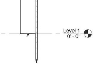
Figure 13.22. Unlocked layers can be modified in a section view by dragging or with the Align or Move tool.
Notice that there are also controls for layers that are locked. Editing the wall with a control of a locked layer changes the Base Offset or Top Offset value and will automatically adjust any Base Extension or Top Extension distances you previously established.
In another common design and construction scenario, you may need to specifically control how two or more walls behave when they intersect. There are a number of ways to customize these occurrences. Let's examine two scenarios where wall joins may need to be edited: phasing conditions and acute angled corners.
When you create a model for a renovation of an existing building, you will likely create elements that are existing, demolished and new. In the example shown in Figure 13.23, a new wall and a wall to be demolished are intersecting an existing wall. Notice that the walls are cleaning up with each other as they normally would if they were all in the same phase.

If you would like to change the graphic behavior of the new and demolished walls when they intersect the existing wall, follow these steps:
Select the new or demolished wall. Right-click the grip control at the end of the wall you'd like to modify and select Disallow Join.
This will cause the walls to overlap, as shown in Figure 13.24.
To complete the operation, you can use the Trim/Extend Single Element or Trim/Extend Multiple Elements tool or simply drag the endpoints of the walls to create the most appropriate intersecting condition (Figure 13.25).

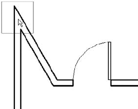
For walls that meet at an acute angle, you can use the Edit Wall Joins tool to control the resolution of the intersection.

Hover your mouse pointer over an intersection of two walls at an acute angle. You will see a box appear around conditions that can be modified with this tool (Figure 13.26).
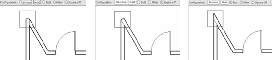
In the Options Bar, you will see a number of choices to help you customize the joining condition between the walls related to the selection.

To cycle through the available options, choose one of the joining types (Butt, Miter, or Square Off) and then click the Previous or Next button. Some options are shown in Figure 13.27.
Note
An important extended modeling technique for walls is the ability to customize the elevation profile of a wall segment. There are two ways you can accomplish this: by attaching the wall's top or base to another element or by editing the sketch profile of the wall. You can apply these methods to basic walls, stacked walls, and curtain walls.
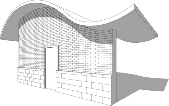
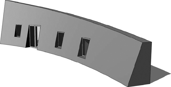
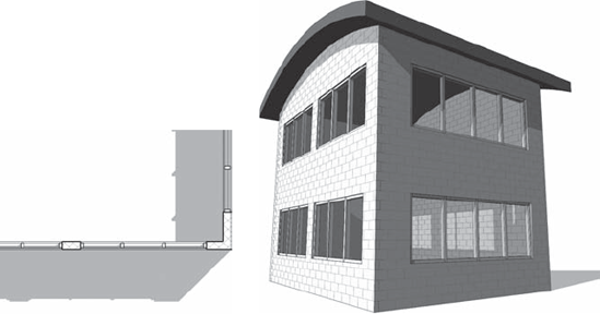
To attach a wall to another element, simply select a wall segment, and you will see the Attach Top/Base button in the contextual Modify ribbon. Once this command is activated, select either Top or Base in the Options Bar and then pick an object. Walls can be attached to roofs, ceilings, floors, reference planes, and even other walls. Figure 13.28 shows a stacked wall that has been attached to a curvilinear roof by extrusion.
When you use the attach method, be mindful of how Revit treats walls that are attached to other objects. After using this method, the instance parameters Top Is Attached and Base Is Attached will show the status of the selected wall's attachment. These are read-only parameters and are for information only. Be aware that the top constraint and any other offset or height value will not display the actual height of the wall when it is attached to something. For example, if a wall whose base constraint is Level 1 and top constraint is Level 4 is attached to a floor slab on Level 2, the wall's top constraint will still be listed as Level 4 in the Properties Palette. This anomaly does not affect other calculations such as wall length, area, and volume.
Automatically Attaching Walls to Floors
When you create a standard floor by sketching a boundary, the floor is hosted on a specific level. After you complete the boundary sketch and finish the editing mode, Revit offers you some help to attach walls to the floor. Any wall whose top constraint is the level on which the floor is hosted can be automatically attached to the bottom of the floor.
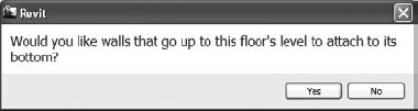
As a bonus, you can access this functionality at any time—not just when you create a floor. If you forgot to attach the walls to the floor when you first modeled the floor, simply select the floor and then click Edit Boundary. Click the Finish Edit Mode button and you should be prompted to attach walls to the floor.
The second method of modifying wall profiles is to edit the sketch profile of the wall. To do this, select a wall and click the Edit Boundary button in the contextual Modify ribbon. This will open a Sketch mode in which you can draw a new boundary for any edge of the wall shape, as shown in Figure 13.29. Click Finish Edit Mode to complete the operation.
Whether you are working on traditional architecture, restoration of historic buildings, or freeform design, you may need to create walls that are irregular in shape. The Model In-Place tool, found in the Component drop-down on the Home tab, lets you create any wall style independent of the constraints of the layer structure described in the previous sections of this chapter. Figure 13.30 shows an example of such a wall created with the solid geometry tools also found in the Family Editor.
You can refer to Chapter 15, "Family Editor," to explore the various modeling techniques available in the Model In-Place mode. Remember that the selection of the family category is important to the behavior of the custom geometry. Select the Walls category to allow your custom elements to be scheduled with other walls and for hosted elements such as doors and windows to be placed.
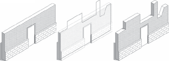
Walls in a building—especially exterior walls—are often composed of several wall types made out of different material combinations and with different widths that stack one on top of another over the height of the façade. Because these walls usually sit on top of a foundation wall, you would likely want to establish an intelligent relationship among these different wall assemblies so the entire façade acts as one wall (for example, when the foundation wall moves and you expect walls on top of the foundation to also move). This is where stacked walls can help.
Note
Stacked walls allow you to create a single wall entity composed of different wall types stacked on top of each other. Before you can create a stacked wall, some basic wall types need to be preloaded in your project. To help you understand how stacked walls work and how to modify one, follow these steps:
Open a new session of Revit and make sure at least three levels are defined. If you don't have three levels, switch to an elevation view, add a few levels, and then go back to the Level 1 floor plan view.
From the Home tab on the ribbon, pick the Wall tool and select Stacked Wall: Exterior—Brick Over CMU w Metal Stud (you can find stacked wall types at the bottom of the list in the Type Selector). Draw a segment of wall in the Level 1 floor plan.
Select the wall segment. In the Properties Palette, click the Edit Type button and then duplicate the wall type to create a new stacked wall called Mastering Stacked Wall.
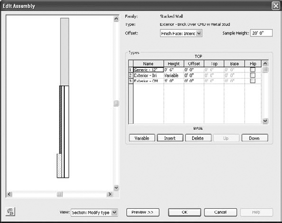
Click the Edit button in the Structure field to open the Edit Assembly dialog box. Open the preview pane and set the view to Section. When you're editing the stacked wall type, you'll notice that the Edit Assembly dialog box (Figure 13.31) is slightly different from when you're working with a basic wall. Rather than editing individual layers, in this dialog box you are editing stacked wall types and their relationships to each other.
Click the Insert button to add a new wall to the stacked wall assembly. A new row appears in the list and allows you to define a new wall. Select the Generic - 12" [300mm] wall type from the Name list and enter a Height of 10'-0" [3000mm] (the height value is not important in this exercise).
At the top of the dialog box, find the Offset drop-down list and change the setting to Finish Face: Interior. This will align the interior faces of the stacked walls and allows you to use the Offset field in the Types table to adjust each stacked wall type in a predictable manner.
Select the row of the generic wall type by clicking the row's number label at the left side of the table. Click the Variable button to allow the wall to vary in height to adjust with varying level heights. Note that one row must have a variable height, but only one row in the assembly can be assigned as such. All others must have a specific height value.
Go back to the Level 1 floor plan and draw a new wall with the Mastering Stacked Wall type, setting its top constraint to Level 3 in the Options Bar.
Cut a section through the model and change the heights of Level 1 and Level 3 to see the effect this has on the wall (make sure the level of detail in the section is set to Medium so you can see the layers of the wall). You'll see that changing Level 2 does not change the bottom walls because they are of a fixed height; however, changing the height of Level 3 changes the height of the variable wall.
At any time, you can break down a stacked wall into its individual wall types. To do this, select a stacked wall and from the right-click menu select Break Up. Once a stacked wall is broken up, the walls become independent and there is no way to reassemble them back to a stacked wall. The base constraint and base offset of each subwall are the same as the stacked wall. For example, if the stacked wall was placed on Level 1, the base constraint for an upper subwall would still be Level 1, with the height difference accounted for in the wall's Base Offset parameter. This can be modified in the Properties Palette if necessary.
The following are some important notes about stacked walls from the Revit User's Guide (from its "Vertically Stacked Wall Notes" section):
When you create a wall schedule, vertically stacked walls do not schedule, but their subwalls do.
When you edit the elevation profile of a stacked wall, you edit one main profile. If you break up the stacked wall, each subwall retains its edited profile.
Subwalls can host sweeps; stacked walls cannot.
Subwalls cannot be in different phases, worksets, or design options from that of the stacked wall.
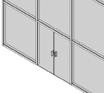
To place inserts such as doors and windows in a stacked wall, you may need to use the Pick Primary Host tool to switch between subwalls composing the stacked wall. For example, the door shown in Figure 13.32 is outside the upper wall because the main host of the door is the bottom subwall.

To place the door properly, select it and then click Pick Primary Host from the Modify | Doors tab in the Host panel. Place your mouse pointer over the wall and select the upper subwall (you may need to press the Tab key to select the correct component). The door will then be properly hosted in the upper wall, as shown in Figure 13.33.

Curtain walls and curtain systems in Revit are unique wall types that allow you to embed divisions, mullions, and panels directly into the wall. They have a distinct set of properties, yet still share many characteristics of basic walls. A curtain system has the same inherent properties of a curtain wall, but it is used when you need to apply a curtain wall to a face. Curtain systems are usually nonrectangular in shape, such as the glazed dome shown in Figure 13.34.

A curtain wall is defined by the following elements and subcomponents:
- The Curtain Wall
A curtain wall is drawn like a basic wall and is available in the Type Selector when the Wall tool is activated. It has top and bottom constraints, can be attached to roofs or reference planes, can have its elevation profile edited, and is scheduled as a wall type. When a curtain wall is selected in a model, the overall curtain wall definition is displayed as a dashed line with extensions at both ends of the segment:
The dashed line of the overall curtain wall definition represents the location line of the wall. This is important if you are placing a curtain system on a face because the placement will be based on the location line. The location line of a curtain wall also determines the measurement of room area. Even if the Room Area Computation option is set At Wall Finish, a room's area will be measured to a curtain wall's location line. For more information, refer to a post on the Do U Revit blog (
http://do-u-revit.blogspot.com/2010/04/room-area-and-curtain-walls.html).So, how do you adjust the location line of a curtain wall? This is accomplished by modifying the offsets in the mullions and panels you assign to a curtain wall or system. We'll cover this process in the section "Customizing Curtain Wall Types," later in this chapter.
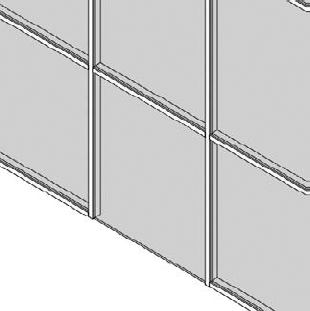
- Curtain Grids
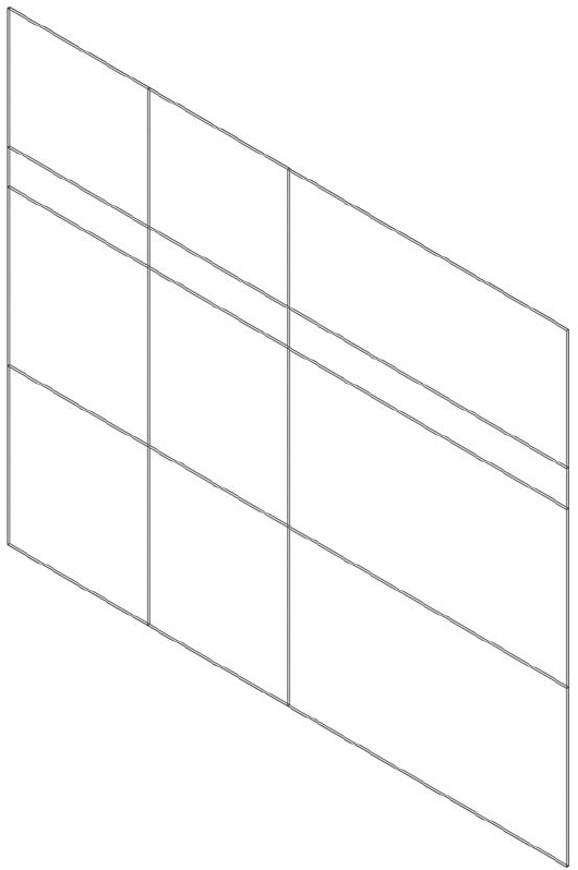
These are used to lay out a grid, defining the physical divisions of the curtain wall. You can lay out grids freely as a combination of horizontal and vertical segments, or they can be predefined in a curtain wall's Type Properties in regular spacing intervals. Figure 13.35 shows a freely designed layout of curtain grids and expressive curtain panels in between.
- Mullions
These represent the structural profiles on a glass façade and in Revit they follow the curtain grid geometry. Mullions can be vertical or horizontal and can be customized to any shape based on a mullion profile family. Offsets specified in a mullion's Type Properties affect how the mullion is placed relative to the curtain wall's location line.
- Curtain Panels
These fill in the space between the curtain grids. Offsets in a curtain panel's Type Properties determine how the panel is placed relative to the curtain wall's location line. Curtain panels are always one of the following:
- Empty Panels
No panel is placed between the grids.
- Glazed Panels
These can be made out of different types of glass that can have any color or transparency.
- Solid Panels
Panels can be created with custom geometry in the Family Editor and can include anything from doors to spandrels to shadow boxes to solar fins.
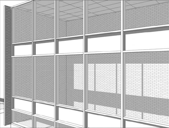
- Wall Types as Infill
When you have a panel selected, you can also choose a basic wall type from the Type Selector to fill the space between the curtain grids. All wall types in the project will be available for your selection. An example of this application would be interior office partitions in which the lower portion is a standard wall and glass panels fill the upper portion.

Let's go through a quick exercise to become familiar with the creation of a simple curtain wall. To create a curtain wall, you can either model a standard wall, then change its type to Curtain Wall, or select a curtain wall type from the Type Selector when the Wall tool is active.
From the Home tab in the ribbon, select the Wall tool. From the Type Selector (in the Properties Palette) select Curtain Wall 1.
In the Level 1 floor plan, draw a single curtain wall. Go to a 3D view to see the result.
The basic curtain wall definition has no predefined grids or mullions. The wall segment you see is actually just one big system panel that you will need to divide. Note that if you create a curved segment for a curtain wall, the panels are always straight segments. Thus, if you try to make a curved segment with Curtain Wall 1, there will only be one straight panel segment between the endpoints of the curve until you start to divide it up with curtain grids.
Divide the wall into panels using the Curtain Grid tool from the Home tab. Position your mouse pointer over the edges of the wall to get a preview of where the grid will be placed (select a vertical edge to place a horizontal grid or select a horizontal edge to place a vertical grid).
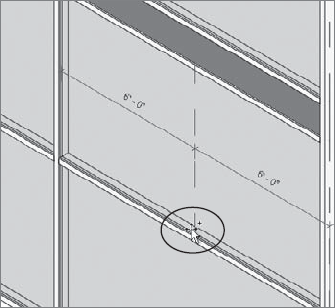
Revit offers some snapping options when you are placing curtain grids that will help you divide the panels and subsequent divisions at midpoints and thirds. Watch the status bar for snapping prompts because there are no graphic indicators of the snapped positions other than the mouse pointer pausing. Place grids on the wall segment so that you get something like the wall shown in Figure 13.36.
From the Home tab, select the Mullion tool. Notice that you can select from a variety of mullion types in the Type Selector; however, the default choice is adequate for this exercise. At the right end of the ribbon, you will see the Placement panel with three options for placing mullions: Grid Line, Grid Line Segment, and All Grid Lines. You can place mullions on the curtain wall using any of these methods. Give each a try to see how they work.
Note
Next you'll replace panels in the wall you just created. As we explained earlier, panels are subcomponents of the overall curtain wall, so you may need to press the Tab key to select a panel and view its properties. Revit has special selection tools for curtain walls that are available in the right-click context menu when you highlight a mullion or a panel. In the following exercise, you will replace the narrow band of glazing panels with solid panels.
In a 3D view, select one of the glazing panels in the narrow horizontal band (press the Tab key to select it if necessary).
From the right-click context menu, choose Select Panels

With all the glazing panels selected along the horizontal grid, go to the Type Selector and find the type named Solid under the family System Panel (note that the Glazing panel type is in the same family as the Solid panel).

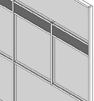
Finally, you will practice the techniques to add or remove segments of curtain grids to refine our curtain wall design. One important fact to remember when working with curtain grids is that they are always implied across the extents of the curtain wall. When we say they are implied, we mean they are not necessarily expressed on all panel segments. To further elaborate, you will add a curtain grid to the midpoint of the right, center panel and delete the division between the two panels to the left of the added grid as shown in Figure 13.38.

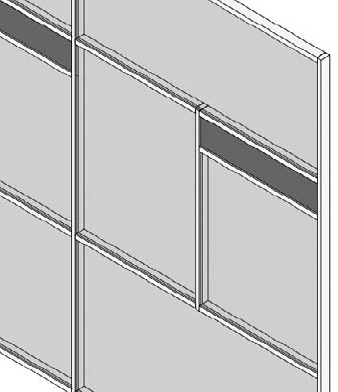
Begin by activating the Curtain Grid tool from the Home tab. In the Placement panel at the right end of the ribbon, click the One Segment button. Hover your mouse pointer over the bottom edge of the right-center panel, snapping to the midpoint of the panel (Figure 13.39).
The second step is tricky. You do not continue creating another division in the short panel above the center panel. Instead, press the Esc key or click the Modify tool to exit the Curtain Grid command. Select the vertical grid line you created in step 1 (you may need to press the Tab key until you see the dashed line indicating the curtain grid). Notice that the grid extends the entire height of the wall (Figure 13.40).
With the curtain grid selected, click the Add/Remove Segments button in the Modify | Curtain Grids panel of the ribbon. Pick the segment of the curtain grid that passes through the short panel. Press the Esc key and you should see that the short panel is also split in half.
Activate the Mullion tool and place mullions on the division between the two center panels, as shown in Figure 13.41.
Press the Esc key or click Modify. Select and delete the horizontal mullion between the two left panels (this step is optional).
Similar to the process of adding grid segments, select the horizontal curtain grid below the narrow band and click the Add/Remove Segments button in the ribbon. Click the segment in the left-center panel. If you did not delete the mullion in step 5, a warning will appear prompting you to delete the mullion segment. The result should look like the wall shown in Figure 13.42.

In the final exercise of this section, you will swap one of the curtain panels for a door panel. Door families for curtain walls can be found in the Doors folder of Revit's default library, but they behave differently than regular doors. The height and width of the curtain wall door is driven by the curtain grids—not the Type Properties of the door.
From the Insert tab on the ribbon, locate the Load From Library panel and click the Load Family button. Navigate to the Doors folder of Revit's default library and load the
Curtain Wall Dbl Glass.rfafamily.Zoom into the bottom-middle panel in your curtain wall. Delete the mullion under this segment as shown in Figure 13.43 (you don't want to have a tripping hazard at your door!). Remember, you may have to press the Tab key to select the mullion.
Select the bottom-middle panel and go to the Type Selector. Find the
Curtain Wall Dbl Glass.rfafamily and select it from the list so the results look like the wall in Figure 13.44. The door swing can be adjusted in plan as any other door in Revit.
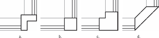
Revit includes special mullions to be used at the corners of two curtain walls. These mullion types are unique in that only one is needed to connect two wall segments. In the default project template you will find four corner mullion types, as shown in Figure 13.45: (a) V Corner Mullion, (b) Quad Corner Mullion, (c) L Corner Mullion, and (d) Trapezoid Corner Mullion.
Corner mullions cannot be customized beyond the shapes included in the Revit project template; however, you can modify the material assigned to the mullions as well as the offset and depth dimensions in the Type Properties. When you use corner mullions between two segments of curtain wall, they will automatically adjust to the angle between the segments, as shown in Figure 13.46.

Before you place a corner mullion, make sure that the endpoints of the two curtain wall segments are cleanly connected. You can drag the endpoint controls of the walls or use the Trim/Extend To Corner tool. To place a corner mullion, simply use the Mullion tool and select one of the corner edges of either one of the wall segments. If you have already placed a regular mullion at the end of a curtain wall segment, select the mullions along the vertical edge and then use the Type Selector to choose a corner mullion type. Remember you can use the right-click menu (select Mullions
In the previous exercises you learned the fundamental techniques of building a simple but custom curtain wall design. To reap some additional productivity from the curtain wall tool, you can predefine almost all the properties necessary to generate a complete curtain wall assembly simply by placing the wall in your project. In the following sections we will examine one of the curtain wall types included with Revit's default project template.
Begin a new project with the Default.rte or MetricDefault.rte template and create a wall segment 30" [9000mm] long using the type Curtain Wall: Storefront. Switch to a 3D view and you will see the wall already has vertical and horizontal divisions along with mullions placed on the divisions. In the example shown in Figure 13.47, we have placed an additional curtain grid and swapped one of the panels for a door type.

Select the sample of Storefront wall you had previously created and click the Edit Type button in the Properties Palette. The settings that drive the generation of this type of wall are relatively easy to understand. Let's review some of the more important options related to these properties:
- Automatically Embed
When this option is enabled, any instance of this curtain wall type will embed itself inside other wall segments. This is useful for modeling extended areas of ribbon or strip glazing (Figure 13.48) instead of using a window family.
- Join Condition
This defines the behavior of the mullion joins. It can be one of the following:
Not Defined (join conditions can be overridden as necessary)
Vertical Grid Continuous
Horizontal Grid Continuous
Border and Vertical Grid Continuous
Border and Horizontal Grid Continuous
- Grid Pattern: Layout
There are four options to define how the vertical and horizontal grids will be arranged in your curtain wall.
- Fixed Distance
The most common setting, which allows you to specify spacing between gridlines. Leftover panel segments must be accounted for in the overall length of the wall.
- Fixed Number
Divides the wall segment into equally spaced panels. When you select this option, the Spacing parameter becomes disabled. In its place, a new integer parameter named Number will appear in the Instance Properties.
- Maximum Spacing
Indicates the maximum spacing distance. Curtain panels will be equally divided over the length of the wall segment, not to exceed the Spacing value.
- Minimum Spacing
Indicates the minimum spacing distance. Curtain panels will be equally divided over the length of the wall segment, no smaller than the Spacing value.
- Mullions
This allows you to specify the mullions that will be automatically applied to the curtain wall. Corner mullions can be applied to either Border 1 or Border 2 for the vertical mullions, but use them carefully as their resolution at corners of will depend on how you construct your wall segments.
You may have already noticed when a panel or mullion is selected from a predefined curtain wall type that they appear with a pushpin icon. This indicates that these elements are part of a system and cannot be changed without additional action.
To change or delete a predefined panel or mullion in a curtain wall instance, select the element and click the pushpin icon. The icon will change to a pushpin with a red X next to it. At this point, you can change the element using the Type Selector or delete it (only mullions can be deleted). Be careful when you attempt to unpin elements from a curtain wall as you cannot re-pin back to the predefined system. Within the active session of Revit, you may be able to return to an unpinned curtain wall element and still find the unpinned icon. This allows you to fix any accidental unpinning, but once your project is closed and reopened, you can no longer reassociate the unpinned elements.
A curtain panel does not have to be confined to a simple extrusion of glass or solid material. You can create any kind of panel family to satisfy your design requirements. When creating a new panel, be sure to select the Curtain Wall Panel.rft or Metric Curtain Wall Panel.rft family template file. The width and height of the panel are not explicitly specified in the family; instead, the outermost reference planes will adapt to the divisions in the curtain wall into which the panel is embedded. If required, you can adjust the panel geometry to offset within or beyond the reference plane boundaries in the family. This is useful for creating butt-glazed curtain wall assemblies.
Complex Curtain Wall Applications
Although covering several specific examples in detail is outside the scope of this chapter, we will offer some real-world examples of creating your own custom curtain panels. Refer to Chapter 15 for guidance on creating your own families. These examples are included in a sample file named c13-Curtain-Wall-Samples.rvt on this book's companion website (www.sybex.com/go/masteringrevit2011).
- Spider Fittings and Sunshades
Generic models can be nested in a curtain panel family. In the example shown here, two instances of the spider component are placed on one edge of the panel. Visibility parameters are assigned to the two spider fittings that enable either the top or bottom spider to be displayed as needed. The spider fittings were downloaded from
RevitCity.comand the sunshade is a Kawneer model 1600 SunShade – Planar downloaded from Autodesk Seek (http://seek.autodesk.com).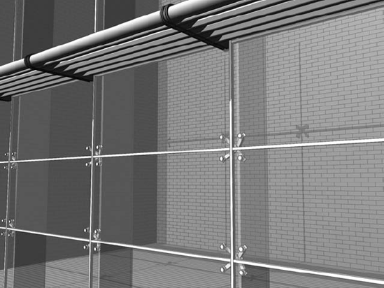
- Spandrel and Shadowbox
Often in glazing applications, the spacing of horizontal members will consist of a pattern including a narrow band or spandrel to mask the floor and ceiling sandwich. Revit does not currently have the ability to define two spacing values, but you can create the spandrel or shadowbox in a single panel family. In the example shown here, the spandrel height is a type property of the custom panel family. Standard mullions are applied to the wall.
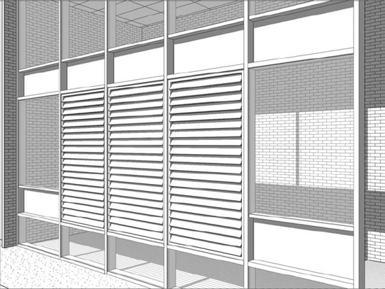
- Louvers
Our last example shows how metal louvers can be embedded in a curtain panel family. The image shown here is a panel developed with a nested generic model. The louver fins are arranged in a parametric array within the generic model, and then the generic model is placed in the panel. The edges of the louver array are constrained to the reference planes in the panel. This parametric louver curtain panel was downloaded from
RevitCity.com.
Often at the early stages of design, as an architect or designer, you need to be able to model curtain wall systems that indicate design intent. These systems need to be flexible and robust enough to allow us to explore design iteration, but they also need to be useful enough downstream as your project moves from concept to design development and then on to fabrication.
In Revit Architecture 2011 you can build Concept Curtain Walls utilizing Revit conceptual massing tools. There are two potential workflows, and it's important to understand the differences. You can model your curtain wall system directly within the project environment from massing forms; or you can build it as a family within a conceptual design environment.
- Project Environment
You can build your forms directly within your project environment using the in-place massing tools. When constructing concept curtain walls through the In-Place Mass tool, the conceptual design environment does not have 3D reference planes and 3D levels.

- Conceptual Design Environment (CDE)
You create your concept curtain wall designs in the Revit Conceptual Design Environment (CDE), which is a type of family editor. These forms reside outside the project environment. You can then reference these massing families into a project environment, allowing you to explore contextual relationships with the building form.
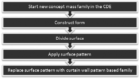
You start by designing your conceptual form that will represent the shape and form of the surface of the curtain wall. You are then able to subdivide the surface of this form using a grid system, referred to as a UV grid. As surfaces are not always planar (flat), a UVW coordinate system is used to plot location across the surface. This grid system automatically adjusts following the natural contours of a non-planar surface or form. The UV grid is then used as a guide for patterning the surface. You can investigate how you might panelize the surface to make it constructible by applying a geometric pattern to the surface. This pattern provides a basic graphically representation of how the panel may look. These graphic patterns can then be replaced with parametric components that automatically conform to the divided surface.
Let's take a look at the basic tools that will allow you to divide the surface of a conceptual form:
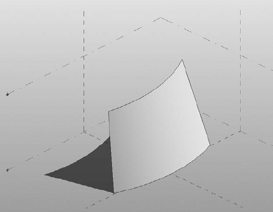
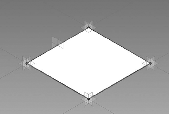
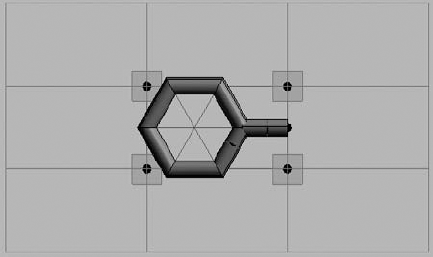
Start by opening
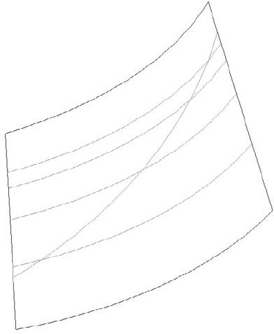
c13-Square-Panel.rfafrom this book's companion web page atwww.sybex.com/go/masteringrevit2011. This file represents a simple conceptual shape for a curtain wall design (Figure 13.49).Select the form and then click Divide Surface on the Modify | Form tab in the ribbon. This will divide the surface of the form and you will see horizontal and vertical grids displayed. This is the UV grid.
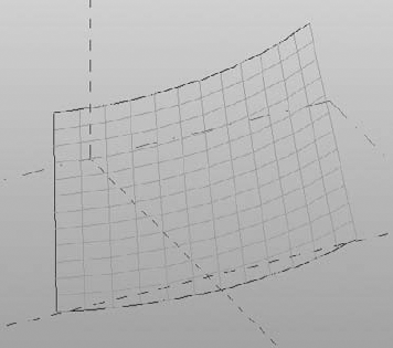
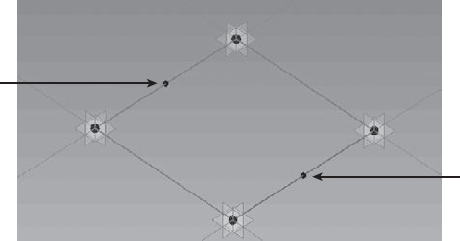
Note that you can control the display of the UV grid when it is selected (Figure 13.50). To modify the display, click the U Grid or V Grid button in the UV Grids And Intersects panel on the Modify | Divided Surface tab of the ribbon.
Make sure UV grids are both displayed and the surface is selected. Notice how the Options Bar provides a number of settings for you to modify the divided surface. You can control the U grid and V grid by a number or with a specific distance. If you select the Number option, you can enter a number of divisions that will distribute evenly across the surface.
Select Distance, which will allow you to enter a specific absolute distance between grids across the divided surface. Under the Distance setting, there is also a drop-down menu that also allows you to specify a Maximum Distance or a Minimum Distance, which are similar to the constraints described earlier in this chapter for basic curtain walls. Make sure the surface is divided by Number, with a U grid of 10 and a V grid of 10.
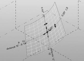
With the UV grid selected, you will see a 3D control (XYZ axis arrows), and an icon appears in the center of the surface. Click the icon to enable the Configure UV Grid Layout command. The display will change (Figure 13.51) and you can now apply specific settings to control the UV grid even further. You have the ability to alter the rotation of the grid, the UV grid belt, and justification of the UV grids at the surface borders. These grid configuration parameters can also be found and modified in the Properties Palette.
In the Properties Palette, set the U Grid Rotation value to 45 degrees, and set the V Grid Rotation value to 45 degrees; then click Apply. Notice how the modified values are updated in the 3D view with the Configure UV Grid Layout command activated.
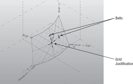
In the Configure UV Grid Layout mode (Figure 13.52), you will see a number of controls—all of which relate to parameters you can also access in the Properties Palette. The arrow cross in the middle of the grid is the grid justification marker. You can drag it to any side, corner, or center of the grid, which will adjust the value of the Justification property of both U and V grids.
The belts represent the lines along the surface from which the distance between grids is measured. The distance is measured by chords, not curve lengths, and can be seen in the Properties Palette as the Belt Measurement parameter for both U and V grids.
As you have seen in the previous exercise, the Divide Surface tool allows you to divide the surface of a form using the natural UVW grid of the surface. However, what if we want to divide the surface with a customized grid pattern? New to Revit Architecture 2011 is the ability to divide a surface by intersecting geometry. By using the Intersect feature you can divide the surface based on the following:
Intersecting levels, reference planes, and even lines drawn on a reference plane
A mixture of U or V grids and intersects
Let's take a look at an example based on our previous file, which will demonstrate how we can use a series of defined reference planes to divide a surface.
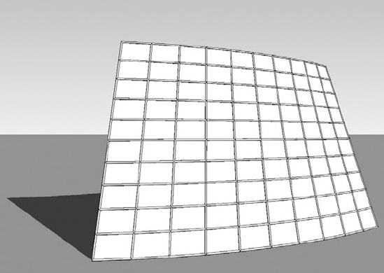
Start by opening the file
c13-Square-Panel-Intersects.rfafrom this book's companion web page atwww.sybex.com/go/masteringrevit2011.Notice that a series of reference lines have been drawn in the X plane; you will use these reference planes to divide the surface of the form.
Select the surface and choose Divide Surface from the ribbon. Click the U Grid tool on the ribbon to disable the display of the U grids.
With the surface still selected, click the Intersects button on the ribbon. Select all the reference planes in the X plane and then click the Finish icon in the Intersects panel on the ribbon. This will divide the surface based on where the reference planes intersect the surface of the form. Note that you could also choose Intersects
Go to the Project Browser and open the 3D view named Surface Only to review the results (Figure 13.53).
Surface patterns allow you to quickly preview in a graphical manner how a panel will work across the surface of the form. As you are not working with complex geometry at this stage, the editing and adjustment to the design concept is quick. Revit provides a number of predefined patterns that are available from the Properties Palette, and they can be applied to your divided surface. You will now apply a surface pattern to a form:
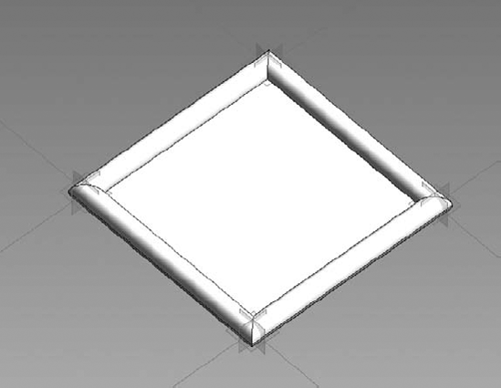
Start by opening
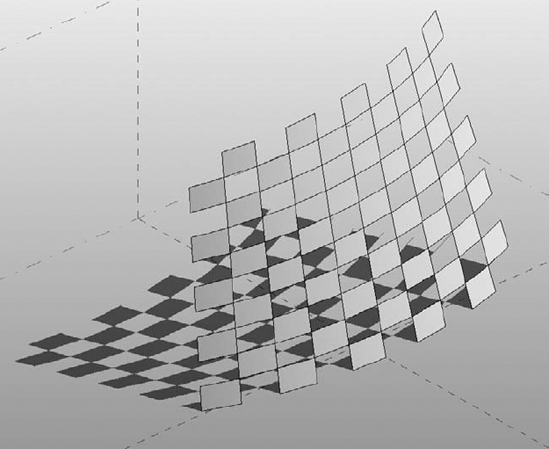
c13-Square-Panel-Pattern.rfafrom this book's companion web page atwww.sybex.com/go/masteringrevit2011.With the UV grid on the form selected, you will notice in the Type Selector that the default empty pattern named _No Pattern is applied to the surface. Open the Type Selector and you will see that you can apply one of a number of predefined patterns to the surface. Click the Rectangle Checkerboard Pattern type to apply it to your surface (Figure 13.54).
Experiment with the various predefined patterns and adjust the UV grid as required to play with the proportions of the patterns.
At any time, you can display both the underlying surface divisions along with the pattern display. With the grid selected, click the Surface button in the Surface Representation panel on the Modify | Divided Surface tab. This display should give you a better understanding of the relationship between the pattern definition and the spacing of the surface divisions.
There will be situations where you will want to edit and control the border conditions for pattern surfaces. Patterned surfaces may have border tiles that intersect the edge of a surface, and they may not end up as complete tiles. You can control the border tile conditions by setting them to Partial, Overhanging, or Empty in the Border Tile instance property of the patterned surface. You will now modify a conceptual curtain wall to examine how the different border conditions affect the surface.
Start by opening
c13-Square-Panel-Border.rfafrom this book's companion web page atwww.sybex.com/go/masteringrevit2011.Select the surface and in the Properties Palette, locate the Border Tile parameter under Constraints. Set the value to Empty and click Apply. Notice that the tiles at the borders are no longer visible, as shown in Figure 13.55.
Next change the Border Tile parameter to Overhanging and click Apply. The border tiles will now show in their entirety, extending beyond the edge of the surface.

When editing a surface in the conceptual design environment, you have the option to choose how surface elements will be displayed. A number of options are available to you, allowing you to customize how you show or hide the various elements that make up a divided surface in a view. If you select either the U or V Grid icon, this will enable or disable the UV grid in the view. The Surface icon allows you to display the original surface, nodes, or grid lines The Pattern icon allows you to hide or display the pattern lines or pattern fill applied to the surface. The Component icon allows you to hide or display the pattern component applied to the surface. If you decide to make any changes to the display using the Surface Representation tools, these changes will not carry through into the project environment. To globally show or hide surface elements you will have to alter this from the Visibility/Graphic Overrides dialog box.
In the Surface Representation panel, you will also notice a small arrow in the bottom-right corner. Clicking this arrow will open the Surface Presentation dialog box, where you will find additional display options for the surface, patterns, and components. You also have the ability to display nodes and override the surface material of the form. Let's practice controlling the surface representation of your form.
Start by opening
c13-Square-Panel-SurfaceRep.rfafrom this book's companion web page atwww.sybex.com/go/masteringrevit2011.With the surface selected, go to the Surface Representation panel in the ribbon and click the arrow in the bottom-left corner to open the Surface Representation dialog box (Figure 13.56).
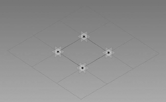
On the Surface tab, enable Nodes; this will display a node at each intersection of the UV grid, as shown in Figure 13.57.


So far, you have created a surface, subdivided it, and applied a graphical representation to the form. You can now begin to add actual component geometry similar to mullions and panels. Note that although the underlying graphic pattern will remain, the component geometry will take precedence. To begin this process, you will create special curtain panel families using the Curtain Panel Pattern Based.rft or M_Curtain Panel Pattern Based.rft family template. This type of panel family can be applied to the divided surface to populate it with architectural components, adding realistic definition to your conceptual curtain wall surface.
In the following exercise, you will build a simple rectangular panel and apply it to your divided surface.
Click the Application button, choose New
Figure 13.58 shows the pattern-based curtain wall family template, which consists of a grid, a series of reference lines, and adaptive points. The grid is used to lay out the pattern of the panel. The adaptive points and reference lines act as a rig, defining the layout of the panel. You can construct solid and planar geometry within and around the reference lines to form the panel.
When a panel is applied to a divided surface, the points in the panel adapt to the UV grid and the panel will then flex accordingly. As a general rule, the grid pattern in your curtain panel family should match the pattern on the divided surface to which it is applied. For example, if you have applied a hexagonal pattern to your divided surface, make sure that the curtain panel family is also using a hexagonal pattern.
You now need to decide what pattern you will use for the component. To change the pattern, select the grid, go to the Type Selector, and change the pattern to Rhomboid. Notice how the adaptive points and reference lines update to reflect the change. Review the various patterns that are available to you. Revert back to the Rectangular pattern.
Modeling a pattern-based curtain panel is similar to how you would sketch and construct a form within the conceptual design environment. You use points, lines, and reference lines to construct geometry.
Select one of the adaptive points and drag it. These points will not move horizontally, only vertically. As you move the point, the reference lines attached to the point will alter the shape. Therefore, as you build geometry on the defined reference lines and an adaptive point is moved or adjusted, the reference lines are altered and the geometry constructed along the reference lines updates to reflect the change.
To reset the adaptive points back to the grid, select the grid and you will notice a Reset Points To Grid button in the Options Bar. Click the button to reset the points.
Select the four reference lines and click the Create Form
Next we will flex the geometry to test its consistency. Select one of the adaptive points and move it vertically. Observe how the geometry flexes, as shown in Figure 13.60, and then reset the points to grid.
Switch to the Home tab in the ribbon and from the Draw panel select the Point Element tool. Place a point on one of the reference planes, as shown in Figure 13.61. This point becomes a hosted point; observe how its symbol is smaller than the adaptive points. Select the point and from the Properties Palette, change the value of the Show Reference Planes parameter to Always. This will make it easier to build geometry using the hosted point in later steps.
From the Home tab and the Work Plane panel, click the Set button (Set Work Plane tool) and pick the work plane of the hosted point.
Draw a circle with a radius of 6 inches [150mm] on the work plane of the hosted point, as shown in Figure 13.62. It can be a little tricky drawing the circle onto the active work plane of the hosted point. Therefore, use the Show Workplane tool to display the active work plane for the point. This will make the process of sketching the circle easier.
Select the circle and the four default reference planes, and then choose Create Form
When building your curtain panels, consider how you will assign geometry to appropriate subcategories. This will ensure you have full control over the elements from a visual and graphical point of view. For details on assigning geometry to subcategories, refer to Chapter 15.
Save the family as
Square-CWPanel.rfa.


Now that you have created a pattern-based curtain panel family, you'll need to load this family into your conceptual mass family and apply it to the divided surface, replacing the graphical pattern with the actual component.
Download and open the file
c13-Square-CWSystem.rfafrom this book's companion web page atwww.sybex.com/go/masteringrevit2011.Load the family file
Square-CWPanel.rfayou created in the previous exercise into this file by clicking Load Family on the Insert tab of the ribbon, or switch to that file and click the Load Into Projects button.In the conceptual mass file, select the pattern and divided surface. In the Properties Palette, click the Type Selector and scroll down the list until you find the name of your pattern-based curtain panel family. Note that your new panel family will be listed under the pattern within which it was designed. The component will now be applied to the patterned surface, as shown in Figure 13.64. Note that the more complex the surface and component, the longer it will take to load.
Now that you have mastered the technique of constructing a simple planar curtain panel, let's take a look at how to create a pyramid type panel. You will add a type parameter to your pyramid curtain panel so that you can vary the apex of the panel.
Start a new family using the
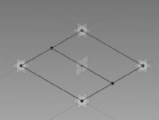
Curtain Panel Pattern Based.rftfamily template.Place a reference point, ensuring it snaps to the middle of one of the reference lines included within the template. Place another reference point on the opposite reference line to the one you previously placed, as shown in Figure 13.65.
From the Home tab in the ribbon, click the Reference tool and ensure 3D Snapping is activated in the Options Bar. Draw a reference line between the two newly placed hosted reference points, as shown in Figure 13.66.
Place another reference point, so that it becomes hosted, at the midpoint of the previously created reference line (Figure 13.67). Select this reference point and from the Properties Palette make sure that Show Reference Planes is set to Always.
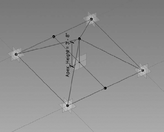
From the Home tab, choose the Set Work Plane tool and select the work plane of the hosted point at the middle of the previously drawn line. Activate the Reference Line tool and uncheck the 3D Snapping option. Draw a reference line vertically in the Z plane from the hosted point. Ensure that the start point of the reference line is locked to the hosted point. You may need to drag the end of reference line, nearest to the point, in the Z direction, before dragging it back to the hosted pointed. This will ensure the lock symbol will appear.
Select the vertical reference line to display the temporary dimension and turn this into a permanent dimension by clicking the dimension icon.
Select this dimension and then choose <Add New Parameter...> from the Label pull-down in the Options Bar. Assigning this dimension to a parameter will allow us to alter the apex of the pyramid panel as needed. In the Parameter Properties dialog box, name the parameter Apex_Height. Click OK to close all open dialog boxes.
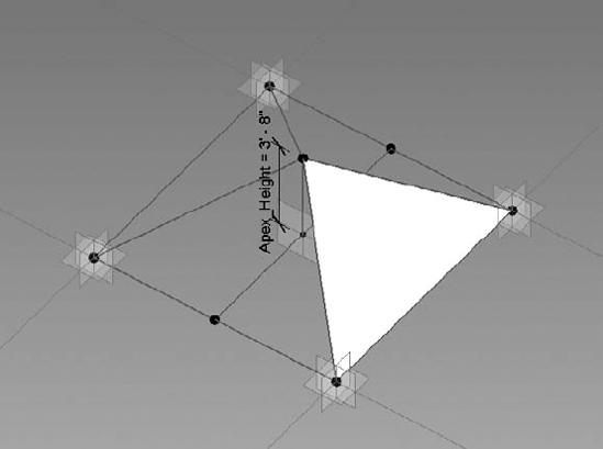
Add a series of reference lines using the 3D Snapping option from the apex to the four points on the base of the pyramid, as shown in Figure 13.68.
You will now create faces on each slope to complete the pyramid shape. To do this, select one reference line from the base and two reference lines on the sloping edges (use the Ctrl key to add lines to your selection) and click the Create Form button. Select the planar triangular face rather than the extrusion (Figure 13.69).
Repeat step 9 for the three remaining faces until you have a completed pyramid, as shown in Figure 13.70.
It is important that we flex the pyramid to check that you can control the height of the apex. Open the Type Properties dialog box and you will see the parameter named Apex_Height. Change the value a few times and click Apply after each change. The pyramid panel should change in height. Save your file as
Pyramid-Panel.rfa.Open the file
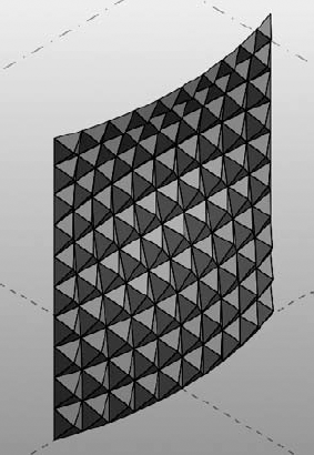
c13-Pyramid-Project.rfafrom this book's companion web page atwww.sybex.com/go/masteringrevit2011. Load yourPyramid-Panel.rfafamily into thec13-Pyramid-Project.rfa. Select the surface, go to the Type Selector, and choosePyramid-Panel. Your pyramid shape curtain panel will now be populated across the divided surface, as shown in Figure 13.71.


Although Revit Architecture includes a variety of patterns you can use for conceptual curtain walls, at present there is no way to create your own pattern-based curtain panel template. The current patterns shipped with Revit Architecture are hardwired so there is no way to modify these either; however, with a bit of creative thinking you can utilize the provided templates to construct panels that will conform to a custom pattern concept. When you consider building a custom panel, it is important to take into account how it will repeat vertically and horizontally. You will need to break it down into to its smallest module. If you think about a repeating architectural pattern such as a masonry wall, its individual component can be broken down into the brick that forms that pattern, which is in essence a rectangle. An example of a hexagon-shaped panel, constructed within a rectangular pattern, is shown in Figure 13.72.
Once you have decided on the design for your panel, look at how the panel could be modularized. To do this, consider laying out the pattern utilizing graph paper. This will certainly help you better understand the layout before attempting to construct the panel using an appropriate template. In Figure 13.73, you will see the hexagonal panel applied across a divided surface.

When designing complex curtain wall systems, the goal is to limit the variety of panels. The more variety you have, the higher the cost because you have to create a greater number of unique panels. When you divide a surface in Revit 2011, the panel sizes can vary quite dramatically. While Revit does not actually offer the ability to limit panel sizes, you can start to reduce the size and variety of panels by nesting curtain panels inside other panels. In the following exercise, you will learn how to nest panels to limit size variation.
Start by creating a simple pattern-based curtain panel family (use either
Curtain Panel Pattern Based.rftorM_Curtain Panel Pattern Based.rft). Make sure the grid is set to the Rectangular type.Select the four reference lines and use the Create Form tool to generate a planar surface.
Similar to the previous exercise, place a hosted point on one of the edges of the surface and then draw a circle with a 6" [150mm] radius on the point's work plane. Use Create Form to generate a swept profile on two edges to represent a mullion as shown in Figure 13.74. Save this panel as
Limit-Panel-1.rfa.Start another new pattern-based curtain panel family, again using the Rectangular grid pattern. Select the four reference planes and use Create Form to generate a planar surface rather than an extrusion.
Select the planar surface and click the Divide Surface tool from the ribbon. You will divide this surface and set the UV grid by number, setting U Grid = 2 and V Grid = 2, as shown in Figure 13.75.
Load the Limit-Panel-1 family into the divided surface panel.
Select the divided surface and apply your panel to the divided surface by choosing Limit-Panel-1 from the Type Selector. This will nest the panel into the subdivisions of the divided surface (Figure 13.76). Save this panel as
Limit-Panel-2.rfa.You can now apply this nested panel into any divided surface. Download and open the file
c13-Limit-Panel-Project.rfafrom this book's companion web page atwww.sybex.com/go/masteringrevit2011.In the
c13-Limit-Panel-Project.rfafile, select the pattern and divided surface. From the Type Selector, select the name Limit-Panel-2. Note that your new panel family will be listed under the pattern within which it was designed. It will take a few seconds for Revit to replace the pattern with the real geometry of the panel. But observe that by nesting the panel inside other panels you have been able to limit the size and variety of the panels (Figure 13.77).

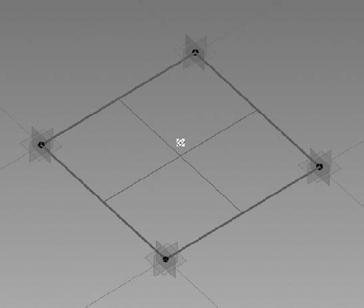

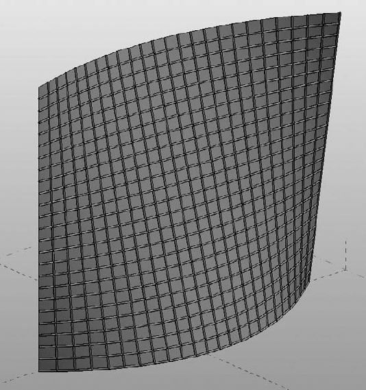
So far the examples covered look at using the UV grid to nest in curtain wall pattern–based families; however, there will be situations where you may want to manually place a panel, specifically at border conditions where you may need to construct custom panels. In Revit Architecture 2011, you can use the new Adaptive Component functionality that is available to you in the pattern-based curtain panel. This functionality is designed to handle cases where components need to flexibly adapt to many unique related conditions. This new functionality also addresses the problems of creating and placing pattern component panels (triangular, pentagonal, hexagonal, and so on) on nonrectangular and irregularly spaced grids. In the following exercise, you will create an adaptive panel and manually place it along the border of a divided surface.
Create a simple pattern-based curtain panel family (
Curtain Panel Pattern Based.rftorM_Curtain Panel Pattern Based.rft) and use the rectangular grid pattern. Select each of the four adaptive points and notice that each point has a number from 1 to 4.Select one of the points; then from the Properties Palette change the Show Placement Number parameter to Always.
Select all the reference planes in the family and choose Create Form; select the Planar Surface option. Save this panel as
My Adaptive Panel.rfa.Download and open the file
c13-StitchSurface-Project.rfafrom this book's companion web page atwww.sybex.com/go/masteringrevit2011.Load the panel you previously created into
c13-StitchSurface-Project.rfa.Notice that in
c13-StitchSurface-Project.rfathe UV grid has been enabled as well as the nodes at the intersections of the UV grid (Figure 13.78). It will be these nodes that you will use to snap your panel.Locate the Families category in your Project Browser and expand the Curtain Panel tree. You will find the My Adaptive Panel type in this list. Drag it into the 3D view window.
With the panel attached at your mouse pointer, place the pointer onto one of the nodes on the subdivided surface to place the first point. Place the remaining points onto the corresponding nodes, as shown in Figure 13.79. Observe how the panel will adapt based on its placement in the surface division.
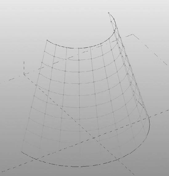
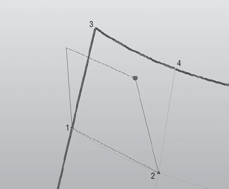
Now that you have completed the design of your pattern-based curtain wall families, you may want to use Revit's scheduling capabilities to assess the quantity and area of panels in your conceptual curtain wall system. This can be useful for calculating approximate costs at the early stages of design. You can schedule panels that have been applied to an in-place mass directly in the project environment; however, it is not possible to schedule panels in the conceptual design environment. You will first have to load your concept mass into a project, where you will then be able to schedule the panels. In this example, you will open a sample file, load it into a project, and then create a schedule, which will list all the panels that make up your conceptual curtain wall.
Download and open the file
c13-Square-Panel-Schedule.rfafrom this book's companion web page atwww.sybex.com/go/masteringrevit2011.Start a new project using either
default.rteorMetricDefault.rte; then load the filec13-Square-Panel-Schedule.rfainto your new project.From the Massing & Site tab in the ribbon, click the Place Mass button and select c13-Squre-Panel-Schedule from the Type Selector. Make sure that the Place On Workplane icon is selected in the Placement panel and place the massing component in the Level 1 floor plan.
Open the default 3D view to view your model (Figure 13.80).
From the View tab in the ribbon, click Schedules and then click Schedules/Quantities. This will open the New Schedule dialog box. Select Curtain Panels from the Category list and click OK.
You will now define the fields that will be included within your panel schedule. Choose Family in the left column and click the Add button to add this field to your schedule. Next add Area and then Count.
Click the Sorting/Grouping tab and check the options for Grand Totals and Itemize Every Instance.
Click the Formatting tab and select the Area field. Make sure the Calculate Totals option is selected. Do the same for Count.
Click OK and your schedule will be created. If you scroll down to the bottom of the schedule, the total area and the number of custom panels in your conceptual curtain wall will be listed.
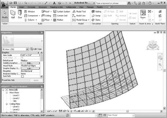
A portion of this chapter was written with the help of David Light.
David Light is currently employed as the Revit Specialist for HOK London, focusing on Revit and BIM as well as helping to drive forward the firm's global buildingSMART principles. David was first introduced to Revit at version 4.5 just after the Autodesk acquisition and has had an unhealthy passion for the technology ever since. Before joining HOK, David worked for the UK's Autodesk Premier Solutions Center providing coaching, training and consultancy in Revit Architecture and Revit Structure. David has developed a reputation as one of the leading UK experts in Revit and is a popular speaker and blogger on all things Revit and BIM.
- Use extended modeling techniques for basic walls.
Walls in Revit are made from layers of materials that can represent generic placeholders for design layouts to complete assemblies representative of actual construction.
- Master It
How can you customize the profile of a wall?
- Create stacked walls.
Exterior walls are usually composed of several combinations of materials with varying thicknesses. These various wall types can be combined into a single entity called a stacked wall.
- Master It
How do you create a stacked wall?
- Create simple curtain walls.
A curtain wall is an assembly of parts including curtain grids, panels, and mullions. They can be created in predefined types with regular horizontal and vertical spacing along with specific panel and mullion types.
- Master It
How do you add a door to a curtain wall?
- Create complex curtain walls.
Revit's conceptual massing environment can be used to create complex curtain wall configurations. Pattern-based panel families can be loaded into the massing environment and populated on a divided surface. These populated surfaces can then be loaded and placed in a project model for documentation and scheduling.
- Master It
How do you create a complex divided surface?