SolidWorks renamed the Animator product MotionManager, and it is now available in SolidWorks Standard. The MotionManager enables you to create movies of parts and assemblies. These movies can show something as simple as a part rotating or as complicated as complex machinery in motion, including motion constrained by assembly mates or motion driven by motors, springs, gravity, and contact.
This chapter does not cover Motion Analysis, formerly COSMOSMotion, because it is beyond the scope of SolidWorks Standard.
SolidWorks uses two different types of motion studies: Animation and Basic Motion. Animation uses key frames to drive the motion, and Basic Motion uses motors, springs, gravity (Physical Simulation), and collision (Physical Dynamics).
The terminology used in this new product can be a little confusing. Here's an overview:
MotionManager. Animator is now MotionManager. Animator as a separate product no longer exists. Its functionality has been absorbed into SolidWorks Standard.
Motion Analysis. COSMOSMotion is now Motion Analysis. Motion Analysis is beyond the scope of this book.
Basic Motion. Physical Simulation is now Basic Motion. Basic Motion uses motors, springs, gravity, and so on; it does not use key frames. It includes Physical Dynamics, which is the calculation of motion due to collisions.
Animation. Assembly Motion is now Animation. Animation uses the key frame method, where the software interpolates between positions established by mates, free-hand drag, or positioning via Triad or XYZ values. Animation is not to be confused with Dynamic Assembly Motion, which is simply dragging parts in an assembly with the cursor to create motion.
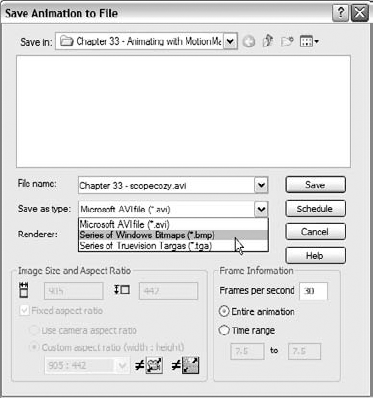
The MotionManager enables you to make animations within SolidWorks and output movie files as *.avi or a series of *.bmp or *.tga still images. You can use it with the default (OpenGL) SolidWorks display, RealView display, or in conjunction with PhotoWorks to create more realistic rendered animations.
Note
PhotoWorks will be replaced by PhotoView 360 in SolidWorks 2011. As of this writing, SolidWorks 2010 SP0 is the current version, and PhotoView 360 does not have any capability to be coupled with animation tools in SolidWorks.
You can control the pixel size and frame rate of the recorded animation to help control finished file size, movie quality, and the amount of time it takes to record the animation. You can rotate or fly through single parts or assemblies. You can make assembly mechanisms move through animating mates, driving them with motors or manually positioning the parts in space.
One of the beautiful things about SolidWorks animations is that you can save them to an eDrawings file. You can send eDrawings to non-SolidWorks users for review, and the file format is small so animations are especially size efficient.
You can access the MotionManager interface in the lower left of the graphics window. The Model and Motion Study 1 tabs enable you to toggle the interface on and off. The Model tab shows the normal SolidWorks interface. You can add tabs to create multiple motion studies. Figure 33.1 shows the lower-left corner of the SolidWorks window with each of the buttons activated. If you cannot see this interface, you may need to turn on the MotionManager. To do this, right-click on a toolbar and select MotionManager from the list of toolbars.

You can animate the following:
Distance mates
Angle mates
Part appearance (including display modes — shaded, wireframe, and so on)
Part transparency
Part visibility
Part position
View/zoom state
Camera position and properties
When you animate colors and appearances, simple colors can fade from one color to another, but any appearance with a texture does not fade; it simply snaps to the next texture at the appropriate time. That is to say that you can fade red to blue, but you cannot fade marble to fabric.
You cannot animate the following:
Changing part dimensions
Changing PhotoWorks materials
Configurations
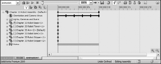
The parts of the interface you will use the most are the key points, the design tree, and the time bar. The filters help you select or view limited sets of items, and the tabs at the bottom enable you to set up alternative studies. Playback speed enables you to change the rate of playback to either take in a long animation more quickly, or to see motion in one area in more detail. The timeline zoom in and out tools enable you to rescale the time interval on the timeline. Figure 33.2 identifies the major elements of the MotionManager.

When recording an animation to a movie file or a series of still images, you have several options for the type of display output to use. The first and easiest is the default SolidWorks display, without RealView. This is most appropriate for fast, technical presentations. You might want to use this to demonstrate the function of a particular mechanism or to simply rotate around a model to demonstrate the model in 3D rather than as a flat image or an eDrawing.
You can also turn on RealView and record the animation. If you do this, you should have appropriate appearances in use for individual parts. RealView appearances enable you to use reflective or textured materials on your parts.
The highest-quality images come through the PhotoWorks renderer. Using PhotoWorks takes much more time than the other options because each individual frame must be rendered just like a normal PhotoWorks rendering. PhotoWorks itself is beyond the scope of this book.
It is often useful to plan any animation that is more involved than just a couple of moves on the screen. You can do this a couple of different ways. The easiest way is to write out a list of moves or positions you want display, with the approximate time of each position or action.
You might also use the storyboard technique professional video houses use. You create a series of images to represent the state of the animation at specific points in time. You can use static screen captures or hand sketches to do this, depending on the complexity of the geometry and animation.
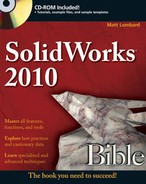
The easiest animations are those you can create with the Animation Wizard. The Animation Wizard accommodates two types. The first is where a part or assembly is simply rotated on the screen, and the second uses an existing exploded view from an assembly. You can combine, reorder, reverse, copy, or move both types of animation sequences within a larger animation.
To create a rotating animation, first click the Animation1 tab at the bottom-left corner of the graphics window. This opens the MotionManager. Remember that you can select or deselect the MotionManager in the list of toolbars. (Choose Tools
After you select the appropriate type of animation and click Next, you select an axis of rotation, the number of rotations, and the direction. An important thing to note here is that the X, Y, and Z axes do not refer to axes of the part; they refer to axes on the screen. Rotating about the X axis is like holding down the right-arrow key on the keyboard. The sample animation that appears in the corner of the Animation Wizard, shown in Figure 33.4, shows what you can expect. It will change direction if you change the option.
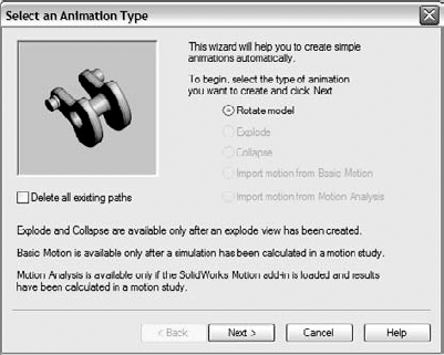

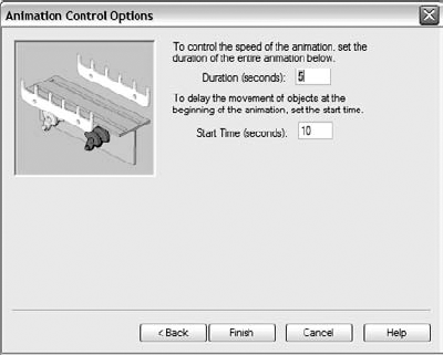
The final step in creating the rotating animation is to determine how long the animation will last, and at what point in the overall animation it should start. Figure 33.5 shows the Animation Wizard page to set these options.
Note
Looping is only controlled during playback. The animation itself has a beginning and an end. If you want to play the finished movie with smooth looping, you should make sure that the start point and the end point of the animation are exactly the same.
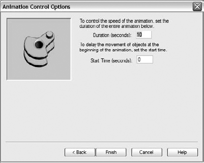
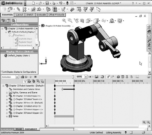
After you click Finish, MotionManager populates the timeline with key points along the timeline for the Orientation and Camera Views. Instead of rotating the part, the software rotates the view. It seems like a semantic difference, but when you start working with moving parts in assemblies while changing the view, the difference becomes important. Notice the heavy black line with diamonds on the row for the Orientation and Camera Views in Figure 33.6. Each diamond (key point) represents a view angle, and the line between them represents that MotionManager will interpolate the view between the key points, making the view transition smoothly. You will learn how to create key points later in this chapter.
The sample assembly on the CD-ROM is named Chapter 33 Robot Assembly, and is saved with an exploded view. You can create your own or use the one I have provided. If you use this file, create a new animation to practice with. To use the Animation Wizard to create an animated explode and collapse, first start with an assembly that has an exploded view and activate the Animation Wizard. Figure 33.3 shows the first page of the Animation Wizard where you select the animation type. Select Explode and click Next. Figure 33.7 shows the second page. Explode animations skip the second step, which is used by Rotate animations.
If you added the explode at the end of the rotate, your animation does both: rotate then explode, each in sequence. Later you will learn how to copy and reverse the key points for the explode to make it collapse and how to adjust key points to make parts move faster, slower, or simultaneously.
You are not limited to the Rotate Animation Wizard to changing the view. You can manually create key points or drive a camera along a path to create the view or transition between views that help you visualize your geometry.
Animating view changes is a simple task in the MotionManager, and once you learn it, you will be able to apply what you learn to making parts and mechanisms in an assembly move in much the same way.
Again, start with the robot assembly. First clear the timeline of any key points. One way to do this is to simply choose File
The purpose of disabling the creation of new views is so you don't accidentally rotate the view and thus change the animation. I can tell you from experience that this is one of the most common mistakes I make when creating an animation.
Best Practice
The best way to handle the Orientation and Camera Views option is to select it (allow view changes) only when you want to establish the view key points, then deselect it when you are done.
To start this animation of the view, you need to deselect the Disable View Creation option, so that the blue telescope appears to the left of the entity in the design tree.
The time bar is the vertical gray line in the timeline area that denotes the current time that you are editing in the animation. When you make a change to any element that can be animated, that change is applied at the time denoted by the time bar. To make a key-point driven animation, the workflow usually involves moving the time bar, making a set of changes, moving the time bar, making another set of changes, and so on. I do the same thing here to demonstrate how it works.
I start by making sure the time bar is set to zero (all the way to the left), and then positioning the view I want to start the animation with. In this case, bring up the View Orientation dialog box (spacebar) and double-click the view named 1.
I want the view to remain static for a couple of seconds when the animation starts. It might be too confusing to start the animation immediately with the view changing. To create this hesitation, I copy the first key point from the 0-second mark to the 2-second mark. It is as easy as it sounds. Click the key point in the same row as the Orientation and Camera Views, and then Ctrl+drag it to the right to the 2-second mark. This causes the first 2 seconds of the view to be static.
Next, move the time bar to the 5-second mark and bring up the View Orientation box again and activate view 2. This causes the view to swing around, and adds an additional key point to the timeline. The black bar between the 2-second key point and the 5-second key point indicates that MotionManager will interpolate the view orientation between the two defined points. The MotionManager now looks like Figure 33.8.
Note
There is a bit of odd functionality here. If you have the time bar selected and press the spacebar, the time bar advances 1 second. If you need to access View Orientation instead of advancing a second, first click in the graphics window or the timeline area to clear the selection before pressing the spacebar.
The next step is to zoom in to the grippers and simultaneously turn the view slightly to give a better view. Before changing the view, though, it would be nice to have another hesitation to give the viewer the chance to see what is there. To create the hesitation, click on the last key point in the Orientation and Camera Views row, and then Ctrl+drag it to the 7-second mark. Then move the time bar to the 10-second mark. Remember that the highlight color is now blue, not the green that longtime users are used to. Also remember that the workflow for copying a particular key is to select, then Ctrl+drag, not just Ctrl+drag. If you Ctrl+drag without the initial select, you may be copying other key points that were also selected at the time. The select operation serves two functions: first to deselect anything else, and second to select only the key point you are interested in.
Note
When creating an animation, you have to be very careful about making changes to anything because those changes may be incorporated into the animation. If you just want to rotate the model to look at something, switch back to the Model tab near the lower-left corner of the SolidWorks window. The first tab always hides the MotionManager and you don't have to worry about changes to the views or positions of parts being recorded.
Once you have the time bar moved to the 10-second mark, zoom in on the grippers using whatever method you use to zoom: Shift+Z, middle mouse button (MMB) scroll, Zoom to Area, Zoom to Selection, or Zoom In/Out. When you are satisfied with the zoom, rotate the view slightly with the mouse, arrow keys, or any of the available toolbar tools. You may also want to pan the view slightly to get it positioned correctly. You need to be careful to make all the changes while the time bar is in a single location, or you may wind up with some very chopped-up view changes in the animation. The idea is to get a good partial side view of the grippers, such as that shown in Figure 33.9. Play the animation to see what you have created.

When you play the animation, it doesn't look very smooth. When the MotionManager interpolates between key points, either for changing views or part positions, the default interpolation mode is linear. That means that it changes between points at a constant speed. This creates the jerkiness because the motion starts and stops abruptly.
To remedy this, MotionManager offers several interpolation modes. Right-click one of the key points that you have created, and select Interpolation mode at the bottom of the list that appears. Another menu flies out, as shown in Figure 33.10.

The icons for the modes should be self-explanatory. My only complaint is that the Ease out icon seems upside down. In any case, curves make smoother motion than lines. Ease in/Ease out create the smoothest motion; Ease in works best at the beginning of a change, and Ease out works best at the end of a change. Snap and Linear should be self-explanatory.
The default is linear, so if you want to change all four of the key points, you have to go through this selection four times, right? No, there is an easier way. You can box+select all four key points, then right-click any of the selected key points, and change them all to the Ease in/Ease out mode. Now play the animation again. Notice how much smoother the view changes are.
When you start to use the MotionManager, you will probably make mistakes. MotionManager does you the favor of recording them all for you in the form of adding key points to the change line for either the part position or view orientation. One way to troubleshoot these types of mistakes is to drag the timeline through the key points, identifying which key points need to be removed. To remove a key point, just click on it and press Delete.
If you are making a long animation that covers a long period of time, say more than 30 seconds, the key points may be close together and difficult to distinguish from one another. You can use the zoom tools in the lower-right corner of the timeline area to zoom the timeline in or out. Zooming in makes the key points appear further away from one another, enabling you to select one that might be right on top of another.
Other mistakes or animation problems will also come up, such as parts that don't move correctly. In most of these situations, the fastest way to deal with them is to delete the problem key points and re-create them. Troubleshooting some errors tends to be fruitless and takes longer than re-creation.
The main weakness of the Rotate Animation Wizard is that it rotates about the screen axis. When I first saw the part rotate that way, I wondered how I could change it. It isn't as easy as maybe it ought to be, but once you understand the process, you can make it as simple as you need to make it. I will use the example of making the camera revolve around the axis of a part regardless of the orientation of the part as the example of how to drive a camera along a path. You can make this process as simple or as complex as you need to. I will start simple and make it gradually more complex.
To state the problem explicitly, rotating the view around the axis of the screen the way the Rotate Animation Wizard does it makes the part look like it is wobbling in space, or spinning while dangling from a string. It doesn't look like it is sitting on a turntable and the table is rotating, which I would guess is the effect most people are looking for. In order to spin the view around the part axis, make a path on a plane perpendicular to the axis, and draw some sort of a path on it.
Starting with the robot assembly from the CD-ROM (Chapter 33 Robot Assembly.sldasm), move to a top view, and open a 3D sketch. When doing prep work like this, it is better if you can work using the Model tab, instead of the MotionManager. This prevents you from creating any unnecessary key points for animatable items.
In the 3D sketch, from the Top view, draw a four-point closed loop spline, as shown in Figure 33.11. The reason I've created this in a 3D sketch is so that I can change the path to a non-planar path if I want to.

The path doesn't have to be perfectly circular; in fact, it might be better if it gets closer to the assembly on one side, making it rather kidney-shaped.
Note
To greatly simplify this task, you can create an offset plane, and sketch an ellipse or circle on the plane rather than using the 3D spline. The 3D spline is intended to give you the most control and flexibility.
The camera will be attached to this spline. You might also want to have a target point for the camera to follow as it goes around the path. I placed a sketch point inside the joint between the Tower and Arm parts. If the assembly or even a part origin is in a convenient location, you can also use this as a place to point the camera.
Once the path exists, exit the sketch and insert a new camera. You can insert a camera by right- clicking the Lights, Cameras and Scene folder and selecting Add Camera. Remember that if the Lights, Cameras and Scene folder does not appear in the FeatureManager, you can make it appear by choosing Tools

Notice when you insert the camera, the SolidWorks graphics window splits into two viewports. The left viewport is your view of the camera, the model, and their surroundings. The right viewport is the view through the camera.
To attach the camera to the spline and point it at the sketch point, make the following settings:
Aimed at target. Select this radio button.
Target by selection. Select this check box and select the 3D sketch point placed inside of the joint.
Position by selection. Select this check box and select the spline.
Set roll by selection. Select this check box and select Top plane.
You can set the camera angle now, but you should experiment a little first. In the left viewport, you can zoom the view up to a small window. Zoom to fit or otherwise zoom out until you can see the sketched spline. A yellow dot connects the lens of the camera to the spline. Drag the yellow dot around the spline slowly and observe the result in the right window. The image on the right in Figure 33.12 shows the arrangement of the viewports. As you drag the camera around the path, watch to make sure that the model stays in the field of view. Sections of the right viewport are grayed out to represent the visible field of view through the camera.
If portions of the model go out of the field of view, or you feel that the camera is too far away or too close to the model, you can move the camera or change the lens. To move the camera, exit the camera PropertyManager and edit the 3D sketch.
Note
Remember that when editing unconstrained 3D sketches, it is best to do it from orthogonal views. Any points you drag move in the plane of the screen. The best way to edit the size of the spline is to view it from the Top view, and drag out individual spline points.
Once you have exited the camera PropertyManager, to get back to it is not exactly the same as most other features in SolidWorks. One way is to right-click it and choose Properties. The easiest way is to simply double-click the camera in the FeatureManager.
If the first method was like filming an object on a turntable, this method is like walking around with a video camera on your shoulder. The first method attached the camera directly to the path, but in this method, you attach the camera to a dummy part, sometimes called a sled, and then move the sled around. The sled should be hidden when the animation is run and left visible for working purposes.
Warning
This functionality may or may not live up to your needs and expectations. You could politely call it "quirky," but it can be made to work within its limited range of capability, and works best when you do everything right the first time without needing edits. One of the cautions in the official SolidWorks documentation on the MotionManager states not to apply path mates to the sled. This seems odd, especially given this particular application looks perfect for the Path mate, but I can vouch that the Path mate does not work well in this application.
The SolidWorks documentation suggests that you use mates with the Use For Positioning Only option, so that the mate places the part, but is not added to the list of mates. I recommend you apply the mate but suppress it instead. If you need to put the part back to its original position, you can unsuppress and then resuppress the mate. The SolidWorks documentation recommends using the Move Component tool with the Along Entity setting, which is essentially the same as just dragging the part, but limiting the drag to a particular axis.
Take a look at this simple animation using a sled Open the Chapter 33 sled track assembly.sldasm.
Start by creating a new motion study. Right-click the Motion Study 1 tab and select Create New Motion Study. Do your new work in this new motion study rather than trying to edit the existing motion study.
Notice that the assembly has two parts: the track and the sled. In this animation, the sled goes around the three sides of the sled and then stops. The first thing to do is to position the sled in the track. I would make a coincident mate between the bottom of the side and the bottom inside face of the track. Figure 33.13 shows this arrangement.

When you move around the corners, remember that the sled is not going to follow an arc path; it interpolates linearly between key points. You can, however, make it rotate and translate at the same time. To do this from the end of a straight section, drag the sled with the left mouse button (LMB) to its new location, and then rotate the part by dragging with the RMB to get it headed down the next straight section. It is also recommended to use more key points when changes in curvature are greater. So around the corners, it may work better if you can place key points more densely than along the straight sections.
The assembly on the CD-ROM has an animation stored in it. You might want to check it out for reference.
Create a new camera by right-clicking the Lights, Cameras and Scene folder. Use the steps I outlined earlier to attach the camera to the midpoint of the short side of the triangular sled, and target the pointy end of the sled. Be careful to not position or aim the camera such that it is half buried in the floor of the track or pointed at the floor. You want the camera to point in a direction parallel to the floor.

You may want to mate the bottom of the sled at a distance from the bottom of the track so the camera is not too close the floor.
Hiding the sled turns out to be more of a task than you might have imagined. Because you have to be able to see the sled to position it, and you have to have a portion of the sled in the field of view if you want to use it to control the camera target, you will have created the animation with the sled always visible. If you hide it, the MotionManager actually make it transparent in the background, and fades from opaque at the other end of the timeline. You need to move the time bar to the other end of the timeline and hide the part there, too.
Once you have created the animation from the bird's-eye point of view, and you can see the camera actually travel around the track, you will want to see the animation through the camera. To do this, first deselect Disable View Key Creation by right-clicking the Orientation and Camera Views item; then right-click the camera in the MotionManager design tree and select Camera View. If you want to return to the bird's-eye view, just reverse the procedure.
In the end, using sleds has its own set of difficulties compared to simply moving the camera without attaching it to any thing. Neither is easy or convenient.
In this chapter, I have already shown you a little about key points to introduce the idea, but here you will learn about how to use them in more detail. You can think of key points as snapshots at particular moments in time. If you said, "At the 4-second mark, the wheel needs to be three inches from the wall," this statement describes a key point. To create a key point, drag the time bar to a new time, and make a change. Any of the animatable items I listed earlier in the chapter can create a key point.
Consider this easy and useful example: a customer wants you to make a little animation of a holder for a stethoscope that he will show to a potential client in PowerPoint. The holder opens, the stethoscope slides out, and then the animation is reversed.
The assembly with the animation saved in it is on the CD-ROM as Chapter 33 – scopecozy.sldasm. The assembly and the completed animation timeline is shown in Figure 33.15.

This animation uses RealView display, which the customer has said is good enough for his purposes. This cuts down the time significantly compared to using PhotoWorks to render the animation.
Your first task is to set up the camera. You could do this without a camera, but cameras are a convenient way to store a particular view, along with settings such as lens angle, perspective, camera position, and target. Plus, if you do decide to use PhotoWorks later, cameras are the only way to get depth of field for additional realism. Another advantage of the camera is that you are able to control the area in view more closely. If you don't use a camera, the area of view is just whatever is available in the view port. With the camera, you can specify a size and aspect ratio, and the available area is cropped appropriately.
Because the stethoscope model is cut into pieces to enable different parts of it to be positioned, you need to position the parts and the camera such that the break between the head and ear pieces is not visible. Leave enough open area so that when the stethoscope comes out, it will not run out of the area of view.
Note
When adjusting the position of the camera, it is often easier to adjust the view itself than to manipulate the camera. In the Camera PropertyManager, deselecting the Lock Camera Position Except When Editing option enables you to manipulate the view directly. This setting is selected by default and will give you the camera with a red X icon if you try to rotate the view when the camera view is on. Switch to camera view and deselect Disable View Key Creation.
I like to start animations with some stillness. If you start an animation with motion, your viewer may not have the time to get settled. A second is usually enough time. Expand the Chapter 33 – Top part, click the key point for the Move row at the zero time mark, and Ctrl+drag it to the 1-second mark. This means that the top will not move between zero and 1 second. Now move the time bar to 2 seconds and open the top by just dragging it up slightly. It should only open about half an inch.
Now move the time bar to the 5-second mark. I want to create a mistake so you see one way to correct mistakes. At the 5-second mark, move the stethoscope out of the holder three or four inches. Try to make sure you do not go far enough that the rubber tube runs into the plastic parts.
Notice that this creates a change bar that shows the position of the scope head part moving continually from time 00.00.00 to time 00.00.05. The motion is supposed to start at the 3-second mark. I've shown you how to fix this in Figure 33.16.

Click the key point for the motion of the scope head part. Then Ctrl+drag it from the 0-second mark to the 3-second mark.
The animation is essentially done at this point, except that now the stethoscope needs to go back into the holder and it has to close. You don't have to manually create all the steps to close the device, although you could if you wanted to. It is more efficient to simply copy and reverse the paths that you have already made.
To copy both sets of motion, the top opening and the head sliding out, drag a window around the key points to select them all, and then Ctrl+drag them to the 6-second mark. Notice that this creates the situation shown in Figure 33.17. If you play the animation at this point, it is not at all what you want. It simply stacks the same motion on top of the original motion. You want it to be reversed.
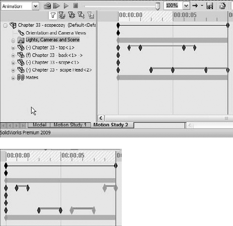
With the newly copied key points still selected, right-click one of them and select Reverse Path. Notice that this now shows symmetrical key points.
The animation is getting close to complete, but now you notice that it would be better if the second half of the animation went by faster than the first half. To do this, move the key points on the right side of a change bar toward the left. You might want to move both key points for the top part closing so that it starts closer to the time when the scope head is back inside the holder. You could even make some of the motion overlap, so the top starts closing before the scope head is fully inside.
Again, if you see a strange effect like the scope head not going all the way back to where it belongs, trying clicking the Calculate button again. Calculate essentially rebuilds the animation after changes.
To make the motion a little smoother, right-click in empty space inside the timeline area, and choose Select All; then right-click one of the key points and select Interpolation Mode. Click the Ease in/Ease out option. Click Calculate again to watch the smoother animation.
If want variable speed, say for the scope head coming out of the holder (for example, it starts coming out slowly and then speeds up), you need to add at least one more key point. To do this, position the time bar to the left of the middle of the first scope head change bar, and click Place Key. This adds a key point in the existing change bar. This is shown in Figure 33.18. Then move the key point to the right. Make sure the new key point uses the Ease in/Ease out interpolation mode. Recalculate, and run the animation again.

If you decide that the entire animation is too fast or too slow, you can also adjust this easily. Drag the right-most key point on the very top row with the Alt key depressed. This scales the entire animation up or down.
The options for the renderer are simply the SolidWorks screen or PhotoWorks. In this example, I used RealView and the SolidWorks screen renderer, which provides sufficient quality for my purposes. The main advantages of PhotoWorks over RealView are it offers a better choice of backgrounds, anti-aliasing, and more shadow control.
Image Size and Aspect Ratio options are available only when you do not use a camera. Without the camera, you are at the mercy of the size and shape of the SolidWorks graphics window until you save the animation to a file.
The Schedule button enables you to schedule the output for a more convenient time. You would normally use this option when using the PhotoWorks, because rendered animations can take many hours to complete depending on render settings, length of animation, and the frames per second setting.
Frame Information enables you to set the quality of the finished rendering. Low frame rates result in choppy motion. High frame rates will be much smoother, but the files may become unmanageably large. High-quality animations generally fall into the 25 to 30 frames per second (fps) range. The human eye cannot resolve faster rates, so it is usually pointless to go any higher than 30.
Depending on the length of the animation and the other settings, test animations might run in the 10 fps range. You might also consider using a specific range of time to test just a portion of the animation.
Unfortunately, many of the decisions that you make regarding animation quality settings directly relate to the time you have to produce the final movie file. The biggest time saver is to avoid PhotoWorks. If RealView suits your needs, you are well ahead on time.
When you go to save the animation, the software prompts you to select a video compressor (codec). Typical options are the Microsoft Video and the Cinepak compressors. Sometimes when you record or play back a movie with a particular compressor, you get a lot of video garbage in the movie. If this happens, try another compressor. I used Microsoft Video for the first movie I recorded of this animation, and there was a lot of video noise. I switched to Cinepak and it worked perfectly.
You cannot change part dimensions when animating. You cannot use features like the Flex to bend parts for an animation. If you can't do any of this, how do you make parts flex during an animation? This calls for another workaround, but it is the only way to actually make parts change shape with the MotionManager. You have to find a way to model the part such that you can make the changes using distance and angle mates in an assembly. That means that you have to do in-context modeling.
A lot of people treat in-context modeling as if it is some terrible infectious disease, but as I pointed out in Chapter 16, it is nothing to be afraid of if you know how to handle it. Still, when you're flexing parts with in-context tricks, it is best if you can keep it simple.
Figure 33.20 shows an assembly that uses this technique to twist the strap as the fork rotates. The assembly used to create this animation is on the CD-ROM, and is called Chapter 33 yoke link.sldasm. The finished movie file is also on the CD-ROM, and is called Chapter 33 yoke link.avi.
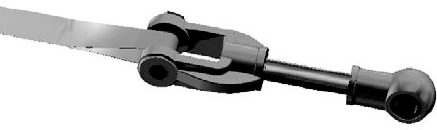
The main trick here is that the strap is made from three separate features. One feature is a revolve that fits the bottom shape of the pin. This feature is part of a part that moves with the fork and pin as they rotate. Another feature is an extrude made from an in-context feature. The in-context relation goes to a dummy part that remains stationary with respect to the rotating fork. And the final feature (really a pair of features) is a loft that goes from the ends of the rotate feature to the ends of the extrude feature.
As the fork part rotates, the in-context relation causes one feature to stay still while the other rotates, and the constant rebuilds the MotionManager does make it look like the strap is flexing.
You can use the same sort of idea to flex living hinges in plastic parts, or just about anything. A cleaner way to do this is to create planes in the in-context part, and then everything else is sketches. If you can drive the flex illusion with planes, you can get this trick to work in a wide range of situations. You usually wind up needing a loft feature, because no other feature is quite as flexible as a loft. It is possible to sometimes use other types of features, but I like the loft the best.
To create the actual motion in the MotionManager, you handle things just like in the other examples, but when you move the time bar, you double-click the angle mate and change the value. Driving animations with angle or distance mates is an effective way to get more exact motion.
In this case, the angle mate is the only thing driving the motion. There is some view orientation movement at the end of the movie, where I also copied the motion from the first half of the movie, and ran it again a little faster with different angle values closer up.
Basic Motion is the functionality formerly known as Physical Simulation. It involves setting motors to turn parts, gravity to move parts and springs, and collisions to create animations that cannot be driven by mates or free motion. It uses a different solver than the rest of the animations in this chapter.
Basic Motion does not take into account effects such as momentum, bounce, resistance/friction, viscosity, reaction forces, and so on. To analyze for these effects, you will need to use Motion Analysis (formerly COSMOS Motion).
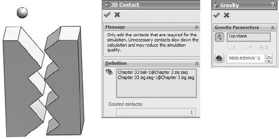
The study type selection box appears in the upper-left corner of the MotionManager. You will need to use Basic Motion, shown in Figure 33.21, for this example.
Figure 33.21 shows an assembly that demonstrates the gravity and contact functions of Basic Motion. The problem is easy to set up. The part that is to move (ball) is underdefined, using only one mate to keep it in plane as it moves. The zigzag part uses a Fixed constraint. The assembly used in this example is on the CD-ROM and is called Chapter 33 zig zag.sldasm.
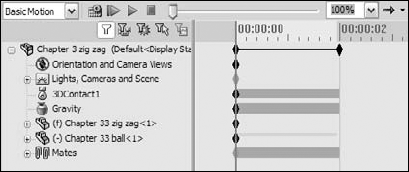
When you have added the physical simulation items, the MotionManager design tree looks like Figure 33.22. Editing items such as contact and gravity does not use the interface options that have been available in the rest of the SolidWorks software starting in the 2008 release. Left-click (select) does not bring up a context toolbar; you have to right-click and access the full RMB menu.
Because this example goes by so quickly, you may wish to use the Playback Speed drop-down menu to get a better look at it. You can also set playback looping options with the drop-down menu to the right of the Playback Speed.
The use of motors does not necessarily require Basic Motion, but if you include springs, or contact or gravity problems, it does. Torsion springs require Motion Analysis, but linear springs only require Basic Motion. This example (on the CD-ROM as Chapter 33 ratchet.SLDASM) shows a motor driving a gear with a ratchet held to the gear teeth by a spring. I've added a swinging ball on a spring to show this isn't simple 2D functionality.

To set up this example, apply a counterclockwise motor to the inside circular edge of the gear, and select the block as the part to move relative to. In this case, I started the motor with a slow rpm (revolutions per minute), moved the time bar out a few seconds, and assigned a faster speed, so the motor speeds up over time.
The linear spring is easy to apply. Select the locations of both ends. In this case, I have circular bosses on the block and the ratchet to hold the spring.
If you keep your animation relatively simple, the MotionManager tools in SolidWorks Standard should be able to give adequate results. If you are using mates to drive motion, be sure to follow mates best practice recommendations. If you are manually positioning parts, remember to place key points closer together if the motion curvature changes.
The changes with PhotoWorks and PhotoView 360 will happen by SolidWorks 2011. Expect a lot of functionality to be added to PhotoView 360, including a link to motion studies.