
Previous chapters have described the basic tools for sketching. This chapter takes you to the next level, teaching you about more advanced sketch tools, how to edit and manipulate sketches, and how to work with sketch text, sketch pictures, and sketch colors. At the end of this chapter, with a little practice to reinforce the tools and techniques, you should feel like you have mastered the topic of SolidWorks sketching and can handle almost any problem that is thrown at you.
Delete is not an edit option. In time, you will find that this is good advice, even if you don't agree with it now. There are times to use the Delete command, but you should use it only when it is necessary. In my own work, I sometimes go to extreme lengths to avoid deleting sketch entities, often just to stay in practice, but also because deleting sketch entities, or even features in a part, increases the likelihood that sketch or mate relationships will be broken.
The main reason to not use Delete in a sketch is that when you are editing a sketch that has other features that are dependent on it, the dependent features may lose their references, or go dangling. Because of this, even when you can use the Delete command instead of making edits, it is still a good practice to edit instead. Deleting relations is not as critical as deleting sketch entities, unless the relations are referenced by equations or design tables.
Before deleting sketch entities, try to understand what types of relationships the change will affect downstream. Be sure to consider other sketch relationships within the current part, mates, and in-context relations in the assembly, and things of this nature. In fact, it is best to have all of this in mind when you are creating relationships to begin with. Try to make relations to the most stable entities available, which usually means having sketches and reference geometry entities as high up in the tree as possible.
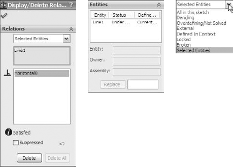
Sketch relations in the Display/Delete Relations dialog box can be divided into the following categories:
All in this sketch. Shows all the relations in the active sketch.
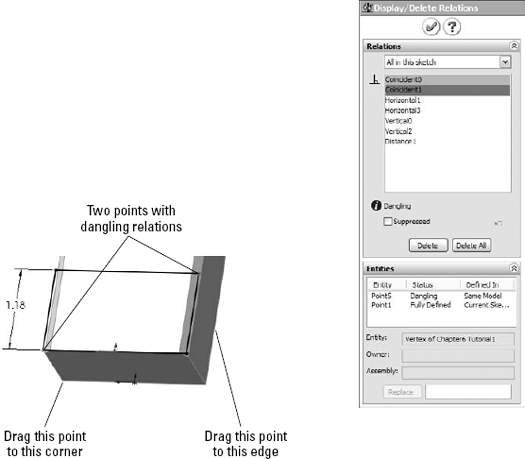
Dangling. Shows only the dangling relations. Dangling relations appear in a brownish-green or olive color, and represent relations that have lost one of the entities that drives the relation. You can repair dangling relations by selecting the entity with the dangling relation, and then dragging the red dot onto the entity to which it should have the relation.
Overdefining/Not Solved. Overdefined relations are any set of conflicting or redundant instructions that are given to a sketch entity, and appear in red. For example, if a line is collinear with an edge and vertical, but the edge itself is not vertical, then both the collinear and vertical relations appear in red.
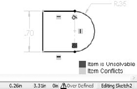
The Not Solved condition often accompanies Overdefined. Not Solved typically refers to a dimension or relation that cannot be applied because of the conflict. The lower-right corner of the screen and the status bar show flags warning that the sketch is overdefined, as shown in Figure 6.2.
When an overdefined situation exists, all the relations and dimensions in a sketch often become overdefined. This can look like a daunting task to repair, especially when the entire problem is caused by a single relation. Do not automatically delete everything. Instead, try deleting or suppressing the last dimension or relation that was added, or a single relation that looks suspect. It is also a good idea to delete red relations before deleting yellow ones. Yellow simply means conflict, while red means a condition that cannot be applied. You can suppress a dimension by setting it to Driven in the right mouse button (RMB) menu, and you can suppress relations in the Display/Delete Relations PropertyManager.
External. External relations connect with an entity outside the active sketch. This includes the part Origin, or any model edges. The term external relations can also signify any relations outside of the part.
Defined in Context. Any relation between features in one part in an assembly and another part is considered an in-context relation.
Locked (Broken). External relations (outside the part) may be locked or broken to increase speed and to lock out parametric changes. There is no advantage of breaking relations rather than locking them. Both are ignored, but locked relations can be unlocked; broken relations can only be deleted.
Selected Entities. Sketch relations are shown only for the selected sketch entities.
Cross-Reference
In-context design, also called top-down, as well as locked and broken relations, is covered in detail in Chapter 16.
Warning
Some of the relations listed in the Display/Delete Relations dialog box may be colored to signify the state of the relation. Unfortunately, colored relations are typically placed at the top of the list to attract attention, but when you select them, they are always gray, and so the advantage of color-coding is always defeated for the first relation in the list. The only way around this is to select a relation other than the first one in the list. If there is only one relation in the list, you cannot see the state color.
A setting in Tool
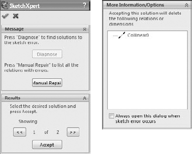
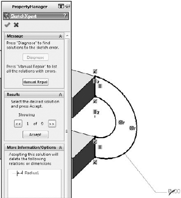
The SketchXpert, shown in Figure 6.3, can help you to diagnose and repair complex sketch relation problems. The Diagnose button at the top creates several possible solutions that you can toggle through using the forward and backward arrow buttons in the Results panel. The Manual Repair button displays all the relations with errors in a window where you can delete them manually.
By selecting the option at the very bottom of the dialog box, you can make the SketchXpert appear any time that a sketch error occurs. To display the SketchXpert manually instead of automatically, you can access it by right-clicking in a sketch.
SolidWorks offers several different tools to help you move sketch entities around in a sketch. In SolidWorks, it is usually recommended to keep the sketch as simple as you can, and to create patterns using feature patterns rather than sketch patterns. The following section discusses the main tools for moving and copying sketch entities.

The Keep Relations option does not actually keep any relations — it deletes the Horizontal and Vertical relations in the sketch, as shown in Figure 6.5 — but it does keep the merged endpoints, as shown in the right-most image of Figure 6.5. This can be useful, especially considering how many sketch relations it would take to make a sketch move like this naturally.


The Modify Sketch dialog box enables you to perform the following functions:
Scale About. The Scaling function in the Modify Sketch tool enables you to scale about either the part Origin or the Moveable Origin. The Moveable Origin is the black origin symbol with knobs on the ends of the axes and at the intersection. The Moveable Origin can be moved and even snapped to entities that are internal or external to the sketch.
Translate. The Translate function of the Modify Sketch tool enables you to click and drag to move the entire sketch, or to select a point and move it to a specific set of coordinates that you type in. If the sketch is dragged onto an external entity and picks up an automatic relation, then a message may appear saying that you can now use Modify sketch only for rotating the sketch because there is an external relation.
Rotate. The Rotate function of the Modify Sketch tool enables you to position the Moveable Origin to act as the center of rotation, and to either type in a rotation angle or drag with the right-mouse button to rotate, as indicated by the cursor.
When you place the cursor over the knobs on the Moveable Origin, the cursor symbols change to indicate the functionality of the RMB. These cursors are shown in action in Figure 6.8. The cursors enable mirroring about X, Y, or both simultaneously.

Note
The Modify Sketch tool is one of my favorite sketch editing tools to use because it is straightforward and doesn't do anything unexpected. It was also an original SolidWorks development, not a tool meant to duplicate existing AutoCAD functionality like some of the previously mentioned sketch tools.
The one thing about Modify Sketch that many people find unsettling is that the red sketch origin moves and rotates along with the rest of the sketch. Once you make peace with the fact that you can't use the red sketch origin for much anyway, this becomes unimportant.
Probably the simplest way to copy sketch entities in a sketch is to select the entities and use Ctrl+C and Ctrl+V or one of the many other methods available for this purpose (such as the RMB button menu, the Edit menu, and Ctrl+dragging).
In addition to copying selected entities within an active sketch, you can also select a sketch from the FeatureManager and copy or paste it to a selected plane or planar face. This creates a new sketch feature in the FeatureManager that is not related to the original, although it does maintain internal dimensions and relations. (External relations are not copied with the sketch.) This is particularly useful when setting up certain types of lofts that use several profiles that can be created from a single copied profile. Copying and pasting is a fast and effective method of putting sketches on planes.
If a selected set of sketch entities has no external relations, then you can select it as a group and move it without distorting or resizing the sketch. For best results with this, avoid dragging end points.
A derived sketch is a parametrically linked copy. The original parent and derived sketches do not need to have any geometrical relation to one another, but when the parent sketch is changed, the dependent derived copy is updated to stay in sync.
To create a derived sketch, you can select a plane or planar face, Ctrl+select the sketch of which you want to make the parametric copy, and then choose Insert
When you create a derived sketch, you cannot change its shape; it works like a block of a fixed shape driven by the parent. However, you can change the position and orientation of the derived sketch. Figure 6.9 shows a derived sketch and its parent. Modify Sketch is a great tool to use for manipulating derived sketches that are not related to things outside the sketch, especially for mirroring or rotating.

Sketch pictures are images that are placed in a sketch on a sketch plane. You can size and rotate the images, give them a transparent background, trace over them, and suppress them. They display as a child of the sketch in the FeatureManager. Image types that you can use as sketch pictures are BMP, GIF, JPEG, TIFF, PNG, PSD, and WMF.
To bring a picture into a sketch, the sketch must first be active. Click Sketch Picture on the Sketch toolbar (it is not there by default, and so you may need to drag it onto the Sketch toolbar from the Tools
To change the size of a sketch picture, you can double-click it and drag one of the handles around the outside of the image. When the picture comes into the sketch, it is usually too big, having been sized at a ratio of 1 pixel to 1 mm. To size a picture accurately, you should include a ruler or an object of a known size in the image. If you cannot do this, the next best thing is to guess the size. Draw a line in your sketch and dimension it to approximately the size of something that is recognizable in the image, and then move the image by clicking and dragging it to lay the dimensioned sketch entity as close over the object in the image as possible.
You can rotate and mirror images, as well, using the Sketch Picture PropertyManager. Images are opaque, and you cannot see the model through them, but at the same time, you also cannot see the images through the model. They are like flat pieces of paper that are pasted to the model or hanging in space.
You can add transparency to images, either by selecting a color or by using the built-in transparency in the image file. When you select a color to be transparent, you will also need to increase both the Matching Tolerance and the Transparency value sliders, which are by default set to their minimum values.
Warning
If a sketch picture has had user defined transparency applied to it, and you double-click the picture, SolidWorks automatically bumps you into the eyedropper mode, which selects a color to be transparent. A single extra click in this mode can make a mess of your Sketch Picture transparency settings by changing the selected transparency color.
Sketch pictures cannot be shown on a drawing associatively. The only way to do this is to capture an image of the sketch picture that is being shown in the model, and put this image in the drawing. PhotoWorks does not use sketch pictures, either, and PhotoWorks Decals are a separate item altogether.
Tip
Although the most common use for the sketch picture is as a tracing guide, you can use it for a wide variety of other purposes. For example, any sort of logo, decal, or display that is on a flat surface can be shown as a sketch picture.
Best Practice
Best practice for using sketch pictures is to put them into a separate sketch near or at the top of the FeatureManager. Even though you can have sketch entities in a Sketch Picture sketch, I recommend keeping them in separate sketches. This is because when you use the sketch entities for an extrude or a loft guide curve, this sketch will be consumed under that feature, meaning the image becomes buried somewhere in your model rather than being easily accessible at the top of the FeatureManager.
When building a model from images, it is often helpful to have three or more images from orthogonal views, similar to re-creating a part from a 2D drawing. If you have a left and a right view, it may be a good idea to put them on planes that are slightly separated so that the images are not exactly on top of one another, which makes them both hard to see. Putting them on slightly offset planes means that one will be clearly visible from one direction and the other visible from the other direction.
Each sketch picture must be in a separate sketch. Figure 6.10 demonstrates the use of multiple sketch pictures to trace the outline of a vehicle, with the partially complete model shown with the images.
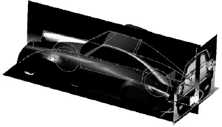
Additionally, you can put multiple sketch pictures inside a single sketch if you want to do that. Both images show up in the FeatureManager, and both can be displayed at the same time, although you may have difficulty if you want to put them on top of one another.
When taking digital photographs to be used as sketch pictures in SolidWorks, you have to consider how perspective affects the image. Perspective can make it difficult to size items in the foreground or background. You should be aware of this, as well as that objects at different distances from the camera will appear at distorted sizes. If you are taking the pictures that will be used as sketch pictures, you can minimize the effects of perspective by standing farther away from the object and using zoom on the camera if possible.
When you are drawing a sketch of an object, you are usually drawing theoretically sharp corners of the model. Real parts usually have rounded corners, so you may have to use your imagination to project where the 3D surfaces would intersect at an edge minus the fillets.
When you are reverse-modeling a part from images, you are not using an exact science. It is better than not being able to put pictures into the sketch, but there is nothing about it that can be considered precise.
Auto Trace is an add-in that you can select by choosing the Tools
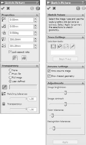
Auto Trace works best with solid blocks of black and white in the Sketch Pictures. To achieve this, you may need to use image processing software and reduce your picture to a two-color (black and white) bitmap, TIF, or PNG image. Even if this pre-processing gives perfect results, don't expect much from Auto Trace.
I can't imagine a situation in which I would use this myself or recommend anyone else use it. In all cases, including idealized demonstration images or those in which traced images would be of the most benefit to the user, such as logos with complex curvature, I believe it would be faster and more accurate to do the tracing manually, even it means using splines.
Sketch text uses TrueType fonts to create text inside a SolidWorks sketch. This means that any TrueType font that you have can be converted to text in solid geometry; this includes Wingdings and symbol fonts. Keep in mind that some characters in certain fonts do not convert cleanly into SolidWorks sketches. Sketch text still has to follow the rules for sketching and creating features such as closed contours, as well as not mixing open and closed contours.
You can make sketch text follow a sketch curve; to space it evenly along the curve, you can control character width and spacing, as well as overall size, by specifying points or actual dimensions. Sketch text can also be justified right, left, centered, and evenly, as well as reversed, rotated, and flipped upside down. Figure 6.12 shows the Sketch Text PropertyManager and some examples of sketch text options.

The icons in the Sketch Text PropertyManager are self-explanatory, other than the Rotated Text option, which rotates individual letters, and not the whole string of text.
You can use the Sketch Text tool multiple times in a single sketch to make pieces of text with different properties. Each string of text has a placement point located at the lower left of the text. This point can be given sketch relations or dimensions to locate the text.
If the text overlaps in places, as shown in Figure 6.12, you can correct this in a couple of ways. First, you can extrude it with the Merge option unselected so that each letter is created as a separate solid body. You can also explode sketch text so that it becomes simply lines and arcs in a sketch, which you can edit the same as any other sketch. You can also adjust the Width Factor and Spacing settings.
Starting in the 2010 version of SolidWorks, you can link the text to a custom property. This means that sketch text can be changed with configurations. Configurations are covered in a later chapter. The text used to extrude a feature can come from Custom Properties, which can be driven by a design table or directly through the Sketch Text PropertyManager.
Custom colors and line styles are usually associated with drawings, not sketches; in fact, they are most valuable when used for drawings. In sketches, this functionality is little known or used, but is still of value in certain situations.
When you select the button, the sketch state colors are used. When the button is not selected, any custom colors that you have applied to the sketch entities appear. If the button is not selected and you have not applied colors to the entities, then the default sketch state colors are used.
You can use sketch colors for emphasis, to make selected sketch entities stand out, or to make sketches with various functions immediately distinguishable. Color Display mode only has an effect on an active sketch. Once a sketch is closed, it returns to the gray default color for inactive sketch entities.
To assign a thickness or a style, you can select the sketch entities to be changed, click the button, and then select the thickness or style. Although a single sketch entity may have only a single thickness or style, you can use multiple thicknesses or styles within a single sketch. Figure 6.13 shows a sketch with the thickness and style edited.
Cross-Reference
Line thickness and line styles are covered in more detail in the discussion of drawings in Chapter 20.

SolidWorks has a lot of functionality that overlaps between multiple topics. The following tools could appear in other sections of the book, but I include them here because they will help you work with and control 2D sketches in SolidWorks. Almost everybody who opens the SolidWorks software at one time or another has to use a sketch, so these tools could be applied by a wide swath of users.
The workflow with this tool is that you start in one sketch, with an active sketch tool, move the cursor over another plane or face without exiting the first sketch, and start sketching the entity on the new plane.
The only real downside of using RapidSketch is that if you sketch on a particular plane or face where other planes or faces might be visible in the background, SolidWorks might interpret certain selections as trying to change sketch planes. To get back to a previous sketch, deactivate the current sketch tool (for example, by pressing Esc) and double-click the previous sketch you want to return to. To move to a later sketch, use the normal sketch exiting techniques.
RapidSketch is a rarely used function in SolidWorks. It has been available for several releases now, but it has not caught on with users. I have yet to see a compelling case for its use.
You are not limited to using sensors only when working with sketches; you can use them outside of sketches in parts and assemblies to warn you when various types of parameters meet various types of criteria.
Figure 6.14 shows the Sensor PropertyManager. You can create sensors for measurements, simulation data, or mass properties. The reason I have included Sensors in this chapter is the measurement options, which enable you to select a dimension and set a range of values or criteria for which you want to be notified. The dimension can be a driving (black) sketch dimension, a driven (gray) dimension on a sketch, or even a driven dimension placed directly on solid geometry.
The third image shows what happens when a sensor finds a condition that you asked it to notify you about.

In addition to turning Sensor alarms on or off, you can also suppress Sensors when they are no longer needed or to improve performance.
Sensors are a great way to keep an eye on particular values, such as wall thickness or clearance between parts. You can use a Sensor to monitor any value you want to monitor but don't drive directly.
Metadata in SolidWorks is non-geometrical text information. Metadata is particularly helpful as keywords in searches as well as in Product Data Management (PDM) applications. If you don't use metadata within your CAD documents, it can be easy to forget that it is there at all.
The sources for storing metadata in SolidWorks files are
Sketch and feature names
Sketch and feature comments (access comments via the RMB menu)
Custom Properties
Design Binder documents
Tags for features (located on Status Bar in the lower-right corner)
Metadata searches can be particularly useful in large assemblies or parts with long lists of features that you need to access for various reasons. You can conduct searches for metadata through the FeatureManager Filter at the top of the FeatureManager. The Advanced Search function in assemblies can also search metadata sources. SolidWorks Explorer is a good first-level data management solution that can search, display, and edit metadata and previews. Windows Explorer can also search properties and tags.
In SolidWorks, the only construction geometry that can be created directly is the construction line. All other sketch entities can be converted to construction geometry by selecting the Construction Geometry option within the sketch entity's PropertyManager or by using the Construction Geometry toggle toolbar button.
SolidWorks terminology is inconsistent, because it sometimes refers to construction lines as centerlines. The two are really the same thing. Centerlines are used for revolved sketches and mirroring, but there is no difference between a centerline and a construction line in SolidWorks.
Construction geometry is useful for many different types of situations. I use it frequently for reference sketch data. You can make sketch relations to construction geometry, and can use it for layout sketches or many other purposes limited mainly by your needs and imagination.
This tutorial guides you through some common sketch relation editing scenarios and using some of the Copy, Move, and Derive tools. Follow these steps to learn about editing and copying sketches:
Open the part named
Chapter6 Tutorial1.sldprtfrom the CD-ROM. This part has several error flags on sketches. In cases where there are many errors, it is best to roll the part back and go through the errors one by one.Drag the rollback bar from just after the last fillet feature to just after Extrude3. If Extrude3 is expanded so that you can see Sketch3 under it, then drop the rollback bar to after Sketch3. If a warning message appears, telling you that Sketch3 will be temporarily unabsorbed, then select Cancel and try the rollback again. Figure 6.15 shows before and after views for the rollback.
Edit Sketch3 and deselect the Sketch Relations display (View
Sketch Relations). Relations with errors will still be displayed. Click Display/Delete Relations on the toolbar (the Eyeglasses tool), and set it to All in This Sketch. Notice that all the relations conflict, but only one is unsolvable: the Equal Radius relation. This appears to be a mistake because the two arcs cannot be equal.
Delete the Equal Radius relation. Select the relation in red and click the Delete button in the PropertyManager. (You can also press the Delete key on the keyboard.) The sketch is still not fixed.
Click the green check mark icon to close the Display/Delete Relations PropertyManager.
Right-click the graphics window and select SketchXpert; then click Diagnose.
Using the double arrows in the Results panel, toggle through the available solutions. All the solutions except one remove sketch relations. Accept the one solution that removes the dimension. This is shown in Figure 6.16. The sketch no longer shows errors in the graphics window, but it still does in the FeatureManager.
Close the sketch. Notice that the error flag does not disappear until the sketch has been repaired and closed.
Use the rollback bar to roll forward to after Extrude2 and Sketch2. Figure 6.17 shows the tool tip message that appears if you place the cursor over the feature with the error. With time, you will begin to recognize the error messages by a single keyword or even by the shape of the message text. This message tells you that there is a dangling relation — a relation that has lost one of the entities.
Edit the sketch (see Figure 6.18). If you show the Sketch Relation icons again, the errors will be easier to identify. When you use Display/Delete Relations (Tools
Click the name of the dangling entity in the Entities panel of the PropertyManager; then click the vertex indicated in Figure 6.18 in the Replace box at the bottom. When you have fixed the errors, exit the sketch and confirm that the flag is no longer on Sketch2.
An easier way to repair the dangling relation is to click on the dangling sketch point once. It will turn red. Next, drag the point onto an entity that you want to reattach the relation to.
Exit the sketch.
Drag the rollback bar to just before CutExtrude1. Edit 3DSketch1. This sketch is overdefined. If the Sketch Relations are not selected at this point, then select them again.
Tip
Because selecting and deselecting the display of the sketch relations in the graphics window is a task that you will perform many times, this is a good opportunity to set up a hotkey for this function. As a reminder, to set up a hotkey, choose Tools
CustomizeKeyboard, and in the Search box, type relations. In the Shortcut column for this command, select a hotkey to use.Double-click any of the relation icons; the Display/Delete Relations PropertyManager appears. Notice that one of the sketch relations is a Fixed relation. Delete the Fixed relation, and exit the sketch.
Right-click anywhere in the FeatureManager and select Roll To End.
Click CutExtrude1 in the FeatureManager so that you can see it in the graphics window and then click a blank space to deselect the feature.
Ctrl+drag any face of the cut feature, and drop it onto another flat face. The Ctrl+drag function copies the feature and the sketch, but the external dimensions and relations become detached. This will only work if Instant3D is unselected.
Click Dangle in response to the prompt. This means that you will have to reattach some dangling dimensions rather than re-creating them. Edit the newly created sketch, which now has an error on it.
Two of the dimensions that went to external edges now have the olive dangling color. Select one of the dimensions; a red handle appears. Drag the red handle and attach it to a model edge. Do this for both dimensions. The dimensions update to reflect their new locations. Exit the sketch and verify that the error flag has disappeared.
Expand CutExtrude1, and select Sketch5 under it. Ctrl+select a flat face on the model other than the one that Sketch5 is on. In the menu, choose Insert
The sketch is blue, and so you should be able to resize it, right? No, it doesn't work that way for derived sketches. You can test this by dragging the large circle; it only repositions the entire sketch as a unit.
Dimension the center of the large circle to the edges of the model.
Drag the smaller circle, and notice that it swivels around the larger circle. Create an angle dimension between the construction line between the circle centers and one of the model edges. Notice that the sketch is now fully defined.
Exit the sketch, and look at the name of the derived sketch in the FeatureManager. The term derived appears after the name, and the sketch appears as fully defined.
Right-click the sketch and select Underive Sketch. Notice that the sketch is now underdefined. The Underive command removes the associative link between the two sketches.


This tutorial guides you through some of the miscellaneous functions in sketches, and shows you what they are used for and how they are used. Follow these steps to learn how to control these items:
Open a new part using a template with inches as units. Open a sketch on the Front plane and draw a construction line starting from the origin 12 inches down (negative Y) away from the Origin.
Insert a sketch picture in this sketch. Use
Sketch Picture 1.tiffrom the CD-ROM for Chapter 6.Resize the image so that the endpoints of the construction line are near the centers of the holes on the ends of the part. To move the image, just double-click it first, and then drag it. To resize it, drag the corners.
In the Transparency panel of the Sketch Picture PropertyManager, select the Eyedropper tool and click in the white background of the image. Make sure that the color field next to the Eyedropper tool changes to white.
Slide the Transparency and Matching Tolerance sliders all the way to the right, or type 1.00 in the number boxes.
Close the sketch, and rename it Sketch Image Front View.
Put the image
Sketch Picture 2.tif, also from the CD-ROM, in a sketch on the Right plane, and resize it to fit with the first image. Center it symmetrically about the Origin. Also, set the transparency to the same setting as the first image.Open a new sketch, also on the Front plane, and draw two circles to match the features on the ends. Extrude them using a Mid Plane extrusion to match the image in the other direction (about 2.5 inches), as shown in Figure 6.19.
Open another new sketch on the Front plane and draw the tangent lines to form the web in the middle of the part. Use the automatic relations to draw the lines tangent to the two cylinders. It is easiest if you the Front View for this. Close the sketch to make a solid extrusion. Extrude this part .5 inches Mid Plane.
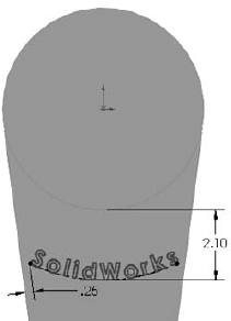
Open a new sketch on the face of the large flat web that you created in the previous step, and offset the arc edge of the larger circular boss by 2.10 inches.
Change the arc to a construction arc and drag its endpoints to approximately the position shown in Figure 6.20. The endpoints of the arc are blue after you drag them. Give them a Horizontal relation, and then dimension them.
To create the 2.10 dimension as shown, select the arc and circle with the Dimension cursor while pressing down the Shift key.
Choose File
Properties. Make sure the Custom tab is active, and type Sketch Text in the first open box of the Property Name column. Make sure the Type is set to Text, and in the Value field, type SolidWorks. Click OK when you are done.Choose Tools
Sketch EntitiesText to initiate the creation of sketch text.Select the construction arc to go into the Curves window.

Deselect the Use Document Font option, click the Font button, and then set the Units to .50 inches. Click the Bold button to make the text thicker. Click OK to exit the dialog box. Click the green check mark icon to exit the sketch text, and then exit the sketch.
Extrude the text to a depth of .050 inches with 3 degrees of draft. The part at this point resembles Figure 6.21.
Performance
Sketch Text is a real performance killer. The more text that you use, the longer it takes to extrude. Draft on the extrusion adds to the time required.
Select the flat face on the other side of the part from where you just extruded the text, and open a sketch.
Select the face and click the Offset button to make a set of sketch entities offset to the inside of the face by .50 inches. Remember that you may have to reverse the offset to get it to work properly.
Open the Line Format toolbar (right-click any toolbar other than the CommandManager and select Line Format).
Select all the sketch lines and change their color using the Line Color tool. Change the line thickness and the line style using the appropriate tools. The sketch now looks something like Figure 6.22.
When you click the Color Display Mode tool, the colors return to regular sketch colors. When you exit the sketch, the line weight and style also return to normal.


If you integrate the use of metadata into your company's modeling process, your SolidWorks models can be a resource for much more than just geometrical data. In this tutorial, discover the hidden treasure of extra information stored as metadata in this model.
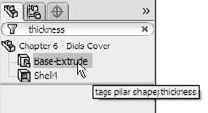
Open the part from the CD-ROM called Chapter 6 –
Dial Cover.sldprt.Check the Custom Properties in this file by choosing File
Properties. Notice the Thickness and Process properties in particular. All the metadata entry interfaces are shown in Figure 6.23.Add a Custom Property with the Property Name Material, type Text, and value ABS. The Custom Property interface is located at File
Check the Comments in this part. Notice that a Comments folder exists near the top of the FeatureManager. Inside it is a list of the features for which I have written comments.
Add a Comment by right-clicking the VarFillet3 feature, selecting the Comment flyout arrow, clicking the Add Comment option, clicking the Date/Time Stamp button, and adding a comment that uses the word Blend.
Check the Tags for the part by clicking the small yellow tag in the lower-right corner of the Status Bar, then click any feature, and double-click in the Tags interface box.
Add a Tag by selecting the Cut-Extrude1 feature and adding the tag pilar.
Right-click any item in the FeatureManager and select Go To from the options.
Type 37 in the box and click the Find Next button. The FeatureManager should highlight a feature near the bottom of the tree named Fillet37.
Click Fillet37 in the Feature Manager and select the Zoom to Selection tool. Zoom to Selection is a magnifying glass with an equal sign in it. The display zooms and pans to a fillet on one end of the part.
Right-click a face of Fillet37 on the model and select Go To Feature (In Tree), which will select the FeatureManager if necessary and scroll to show Fillet37. This sequence of tools shows the importance and interdependence of feature names and the actual geometry.
Type the word Thickness in the filter at the top of the FeatureManager. Figure 6.24 shows the result. Notice how quickly the results appear. Notice also that the metadata item that caused the feature to show in the list can be shown in a tool tip by hovering the mouse over the feature.
Click the X at the right end of the filter to restore the FeatureManager to its original state, and type the word Pilar instead. Now filter for Thermoform.

Sketches can be used as geometrical calculators. Parametrics can be extremely powerful when you can define relationships between geometry. In this tutorial, you will set up a sketch to calculate the complex size and location relationships between the rings of a child's stacking toy.
Open a new part document with inch units.
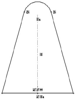
Draw a pyramid with the base centered on the origin, as shown in Figure 6.25. Do not use dimensions, but use sketch relations and construction geometry to enable it to change symmetrically.
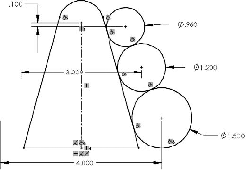
Draw three circles to the right of the pyramid. The bottom circle should be tangent to the bottom and the angled side of the pyramid. The middle and top circles should be tangent to the lower circle and the angled side of the pyramid, respectively. Figure 6.26 shows this process partially completed.
Put a diameter dimension on each circle. In the PropertyManager for each dimension, rename the dimension for ring1dia@Sketch1, ring2dia, and so on. This is shown in Figure 6.27.
Place a dimension from the center of the bottom circle to the construction line, and place the dimension on the far side of the construction line from the circle. This creates a diameter dimension.
Place a dimension for the middle circle in the same way as the bottom circle, but this time, make the dimension value about 75 percent of the first diameter.
Complete the sketch as shown in Figure 6.28, with all the dimensions and sketch relations.
Make changes to the sketch to see which changes it will allow and which it will not. Double-click dimensions and use the wheel in the middle of the Modify dialog box to apply changes smoothly. Try changing each dimension.


Many tools that are available in sketches are not commonly covered in the most popular sources of information, including official training manuals. The difference between a good CAD tool and a great communication tool can be minor functions that just make life a little easier, or the presentation or editing of data a little better. When you explore the capabilities of SolidWorks, it usually rewards you with functionality that is not immediately obvious.