
IN THIS CHAPTER
The difference between templates and formats
Creating drawing formats
Creating drawing templates
Creating blocks
Engineering drawings include a lot of repetitious information from one drawing to the next. The information is not always exactly the same, but it is usually in the same format and of the same type. For example, part drawings always include information about who made the drawing, when they made it, what the material and surface finish of the part are, and some basic notes that depend on the use of the drawing (manufacturing, assembly, or inspection).
All of this information needs to appear consistently on each drawing, every time. However, humans are not always good at following dull routines, which is why we have computers, to help with these boring or difficult tasks.
Even experienced users sometimes cannot tell the difference between templates and formats in SolidWorks. I have mentioned this before, but it is worth mentioning again. Simply put, templates are collections of document-specific settings and default views, saved in the *.prtdot (part template), *.asmdot (assembly template), and *.drwdot (drawing template) formats.
Formats, more formally called "sheet formats," are exclusive to drawing documents, and contain the sheet size, the drawing border-line geometry, and the text/custom property definitions that go with the text in the drawing border. Formats can also include company logo images.
You can save formats in templates; in fact, this is the method that I both use and recommend. Using SolidWorks' default settings, you specify the size and the format when creating a new drawing from a blank template; however, when the format is already in the template, the size is taken care of ahead of time, and so the templates end up being saved as sizes. Of course, you can change formats later if you need to use a larger drawing sheet.
No. This is one of the most common questions from new users. Perhaps if SolidWorks received enough enhancement requests on this topic, they would be willing to change the software to enable the user to transfer the settings from an existing template to one or more existing documents.
Currently, once you create any kind of a document, you cannot change the underlying template. However, you can change all of the settings, which is for the most part equivalent. There are macros available on the Web that you can use to copy the settings from one document to another or to apply settings to a document or group of documents. In particular, there is a spreadsheet available that has a list of settings and options that you can copy to a given document. You will need to search around for these utilities, but they should be easy to find through the newsgroup comp.cad.solidworks, by using Google Groups if you do not have a newsreader.
Different formats must be maintained for different sheet sizes. If you do contract design or detailing work, then you may need to maintain separate formats for different customers. Some people also choose to have different formats for the first sheet of a drawing and a simplified format for the remaining sheets.
Why you should maintain different templates is an easier answer. First, if you put formats on the templates, then you are making separate templates for various sizes. Also, separate templates are frequently created for different units or standards, because templates contain document-specific settings. I also keep a blank template with no format on it just to do conceptual scribbles or to make an informal, scalable, and printable drawing without the baggage that typically accompanies drawings.
Warning
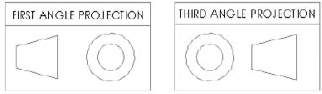
SolidWorks can install with default document templates that use different standards. Be careful of the difference between drawings with ANSI and ISO standards, or more importantly, the use of third-angle projection versus first-angle projection. Figure 20.1 shows the difference between a third- and first-angle projection. Third angle is part of the ANSI standard used in the United States, while first angle is part of the ISO standard used in Europe.
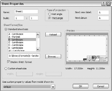
If you work for a company that does a lot of international work, then you may have to deal this issue more frequently. The setting that controls the projection angle is not in Tools, Options (where you might expect it to be), but in the Sheet Properties, which you can access by RMB clicking anywhere on the blank drawing sheet and selecting Properties.

Drawing formats can be either simple or difficult; the good news is that you can choose which one you want to use.
The simple solution is to customize an existing format for your own use. This generally works well, and you can usually finish the task in a few minutes, depending on your requirements. Some options exist for sources. The easiest option is to take the existing SolidWorks sample formats and add a few things such as a company name, logo, and tolerance block to them. You can also use formats from other drawings, editing and saving out as your own.
The sample formats that installed with SolidWorks are located in the Data folder in your SolidWorks installation directory. They include ANSI sizes A to E, and ISO sizes A0 to A4. You can probably find enough space on the formats to place a company logo and some standard notes.
You cannot open a format directly—it must be on a drawing—and so to get a closer look at the format, you must make a new drawing using the format.
Note
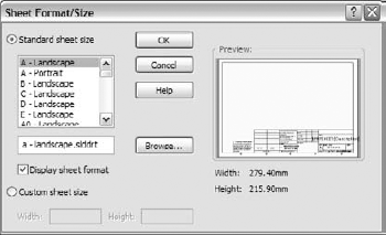
Templates that have been saved with a format already on them skip the step of prompting you to select a format, which allows you to create drawings quickly. If you select one of the default SolidWorks templates, these do not have formats on them and so you are prompted to select one. Figure 20.2 shows the interface for selecting a format that displays after you have selected the template for a drawing.
The SolidWorks drawing environment frequently gives new users trouble. Once you understand how it is organized, it is not so bad, but you may make several mistakes while getting used to it. In the drawing, you are either editing the sheet or editing the format. You can think of the sheet as being a piece of transparent Mylar over the top of the drawing border format. In order to get to the format, you have to peel back the Mylar layer. Drawing views go onto the sheet, and so when you edit the format, any drawing views that may be there disappear. (Of course, drawing views—except for maybe some Predefined views—should not be on a drawing when you are creating a format.)
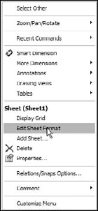
To peel back the sheet and gain access to the format, RMB click a blank area of the sheet and select Edit Sheet Format. This RMB menu is shown in Figure 20.3. Be careful of the terms here, which include Sheet and Sheet Format. The sketch lines of the format light up like a sketch becoming active, and at the lower right-hand corner, on the status bar, a message appears, saying Editing Sheet Format.
The lines in the format border are just like regular SolidWorks sketch entities, but they display a little differently. Also, sketch relations are sometimes not used in formats because solving the relations causes the software to be a bit sluggish. Typically, Trim and Extend functions are the best tools for editing lines.
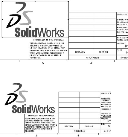
Images that you add to the format work best as bitmaps. Be aware of the file size of the bitmap when you put it into the format, as bitmap images can be large, and all of that extra information will travel around with each drawing that you create from the format. Figure 20.4 shows a bitmap placed in the format.
You can resize the bitmap by dragging the handles in the corners, and move it by simply dragging it. The image to the right in Figure 20.4 shows the Print Preview window. I included it here to show that the outline around the bitmap that displays while you are working in SolidWorks does not print out.
One of the newer functions in SolidWorks is the ability to make a text box of a specific size that causes text to wrap. This is particularly useful in drawings. The image to the left in Figure 20.5 shows a new annotation being added. The image to the right shows the same text box after the corner has been dragged.

Tip
When dragging the text box, it may seem intuitive to drag the middle handle on the end, thinking that shortening the box will cause it to wrap. However, that only works if the box has some space on the bottom to wrap to; SolidWorks does not automatically expand the text box down the way PowerPoint does. You are better off dragging a corner to get the wrap to work.
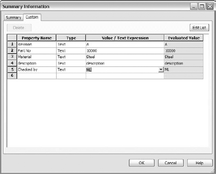
The most important part of the drawing format is the custom properties. While the rest of the format is just for display, custom properties use automation to fill out the title block automatically from matching custom properties in the model document. Custom properties can pull items such as filenames, descriptions, materials, and other properties from the model associated with the sheet, or they can pull data from the drawing itself, such as the sheet scale, filename, sheet number, and total sheets. Figure 20.6 shows the existing custom property formatting in the default format being used for this example.
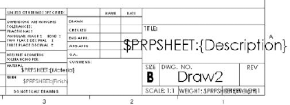
The syntax $PRP or $PRPSHEET indicates that the property that follows the syntax is to be pulled from either the current document (drawing) or from the model specified in the Sheet Properties, respectively. This is an important distinction to make. Most of the time, custom properties are typed in at the part or assembly level so that the data can be reused by drawing properties, BOM, or even design tables.
Notice that all of the notes in the format that are showing raw syntax are pulling data from the model. This is because there are no properties being pulled from the drawing, "Draw2," and the Scale notes are driven by the drawing. When no value exists for the property to display, you have an option of what to show. Figure 20.7 in the image to the left shows the settings in the View menu that control the display of syntax of the custom property links. In general, it is common to turn off the error display, and to show the link variables.
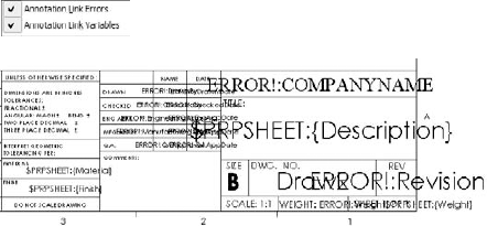
The errors in Figure 20.7 are caused by links to the local document for which there is no corresponding property. For example, the "ERROR!: COMPANYNAME" message is linked to "$PRP: COMPANYNAME," but the local custom property "COMPANYNAME" does not exist. If it existed, but had a null or space value, the error would disappear.
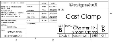
Likewise, with the option to display link variables turned on, the syntax that calls model custom properties displays until there is some value for it to pull from. If a part is put onto the drawing, then some of the properties are filled in because properties and values exist to pull from, and the rest of the properties simply disappear to make space. Notice in Figure 20.8 that the Material property has been filled in, but the Finish property has not. This is because there is either no Finish property in the part on the drawing or a null value in the Finish property.
Tip
When initially setting up the format, it can be useful to have a dummy model already on the drawing. You should delete the views containing the dummy model before saving the format or the template. The dummy model should have all of the custom properties in it that you intend to use in your drawings. This prevents the blank fields or error messages during setup.
Note
If you drag-and-drop a part onto a drawing while editing in the Sheet Format, the views may appear for a split second and then disappear again. This is because you cannot display drawing views while editing the Sheet Format. Once you exit the Sheet Format and go back to editing the sheet, the views can display once more.
It is easy to create annotations that are linked to properties. Begin as if you are creating a note:

Place the note on the drawing. The Formatting toolbar appears.

If the desired custom property is not in the drop-down list shown to the right, then you can type it into the text box or click the File Properties button to edit the properties. This button is not available for the model if there is no model on the drawing, in which case you must type in the name of the property manually.

There is no graceful way to say this, and so I'll just say it: SolidWorks is not really good at manipulating a lot of 2D sketch-line data such as what you find in drawing title blocks. I have gone through the process of making my own formats, as well as the process of importing data from which to create one. By the time you have everything centered, in the right color, and on layers if you are using them, and the text aligned, you have used up more than a couple of hours. If you choose to custom build one size and then use it to create the rest of the sizes, you need to be patient. SolidWorks typically turns off the most useful parametric sketch functions when working with a format (what SolidWorks considers a large sketch) because of speed problems. If you would like to turn these settings back on, they are located at Tools, Sketch Settings.
SolidWorks is not the best program for making a nice-looking drawing border. If you insist on creating your own, set aside some time for it, and have an idea of what you are trying to achieve, maybe sketched out by hand or in a printout of a title block that you would like to replicate.
The Modify Sketch tool may be useful in moving entities around the screen, and even scaling them. You can also access a useful hidden command by RMB clicking the name of the drawing in the FeatureManager, and selecting Move from the menu, as shown in Figure 20.10. A small dialog box appears that enables you to move the entire format by a specified distance.
Tip
If you need to use construction geometry to help you size or locate objects or text while manually creating your Sheet Format, then you do not need to delete the geometry when you are done. You can put all of the construction geometry on a specially created drawing layer and turn the layer off.

If you still think you want to create your format from an imported DWG or DXF file, then locate the file that you would like to import, and open it from the File, Open dialog box. The DXF/DWG Import screen appears, as shown in Figure 20.11.

The sample file used for this example can be found on the CD-ROM for Chapter 20 if you are interested in following along. To make a drawing format, you can select the Create New SolidWorks Drawing and Convert To SolidWorks Entities options. Although one of the other options contains the word format, it is not being used in the same sense, so do not be misled. When this selection is complete, click Next. Figure 20.12 shows the next screen.
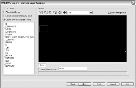
Select the Layers Selected For Sheet Format option. Select the TB layer, leaving the other layers off. Every imported file will be different in this respect, because layers used by title blocks vary widely. Click Next when you have made these selections. Figure 20.13 shows the Document Settings screen.

The important features in the Document Settings screen are the Document template selection and the Geometry positioning options.
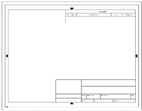
Document template selection is only important if you plan to save the format with a template. Be sure to select a template that does not already have a format saved in it. In the Geometry positioning section, if you can get the software to center the title block for you, definitely take advantage of this functionality and use the Center In Sheet option. Once you are happy with these settings, click Finish. The resulting format is shown in Figure 20.14.
From here, you can add the links to custom properties as described earlier, as well as logo images, loading favorites, and blocks. You can now save the format as described in the next section.
Tip
You can save drawing formats in two ways, either with the template, or separate from the template. You cannot edit formats separate from a template, but they do have their own file type, *.slddrt.
Note
If you are wondering how the extension *.slddrt relates to a sheet format, what is now known as sheet format used to be called a drawing template (thus, the drt of slddrt). What is now called a template did not exist in 1997. The shift in architecture and, more importantly for users, the shift in terminology has left many people a bit confused.
Saving templates is covered in the next section. To save a format, select File
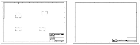
When you have multi-sheet drawings, it is often important to have a simplified or specialized format for the second sheet. Figure 20.15 shows sample page-one and page-two formats side by side.
You can add sheets to a drawing through the RMB menu of the sheet tab at the lower-left corner of the drawing window. If you RMB click the first sheet tab, the sheet that is added gets the format that is used on the first sheet. If you RMB click the second sheet tab, the added sheet gets the second sheet format.
If a format has been changed, and you would like to update a drawing to the new format, this option is available in the Sheet Properties, as shown in Figure 20.16.
Document-specific settings are an important part of the template, and it is probably best to get one size drawing completely set up the way you want it, and then create the other sizes from this drawing. This helps to ensure that the settings, such as bent leader length, font, and line weight, are the same for all of the templates. Uniform settings on drawings give them a consistent look, and make them easier to read. An in-depth discussion of document-specific settings at Tools
Figure 20.17 shows a template using Predefined and projected views. You can access Predefined views on the Drawings toolbar; although it is not there by default, you can place it on the toolbar through the Tools

Once a Predefined view has been placed, you can select an orientation for it from the PropertyManager. Figure 20.18 shows the Drawing View PropertyManager. The orientation for a view is set in the top Orientation panel. In addition to orthogonal views, you can also create isometric and other custom views as Predefined views.
Once the view has been oriented, you may want to create more views on the drawing that also become populated by model geometry. This is where the projected views are used. Make sure that the drawing properties are set to the correct projection angle.
Because the rest of the views have been created relative to the Front view, none of the views needs to be rotated as they would if, for example, the Top view were placed above the Back or Right views.

Although it is not on this drawing, many drawing templates include a third-angle projection symbol as a part of the Title Block, which is in the format. Figure 20.19 shows first- and third-angle projection symbols. These are included as blocks with the sample data in the SolidWorks 2007 installation. Blocks are discussed in more detail in Chapter 22.
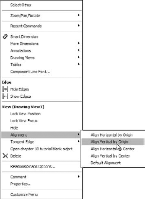
You can align views to one another through a view's RMB menu, as shown in Figure 20.20. Projected views are aligned to one another automatically, but if you chose to use a Predefined view rather than a projected view to one side of the original Predefined view, you can use the Align Vertical by Origin or the Align Horizontal by Origin command. This ensures that the parts in each view are aligned. Aligning by center should not be used for projected views on an engineering drawing, because it is not guaranteed to line up edges in adjacent views.
Four methods exist to populate a drawing with Predefined views:
Drag-and-drop: Drag a part or assembly from the FeatureManager and drop it in the drawing window. All Predefined views are automatically populated.
Insert Model: RMB click a view and select Insert Model. From the interface, browse for the model to be displayed in all of the related (projected) views.
PropertyManager: Select a predefined view, and from the PropertyManager, select Browse in the Insert Model panel.
Make Drawing from Part/Assembly: Click the Make Drawing From Part/Assembly button in the Standard toolbar and select a template that uses Predefined views.
When Predefined views are created, they are set to follow the sheet scale by default; however, you can manually set them to have a custom scale. If you are using the automatic scaling option (found at Tools
Favorites function like styles and formatting in Microsoft Word, or other word-processing software, by adding underlines, bold formatting, and even items such as tolerances and symbols. Hole Wizard Favorites are described in Chapter 17, and work similarly to Dimension and Note Favorites (described in Chapter 22). This chapter is concerned with the fact that favorites can be saved to files, and loaded to documents. In particular, they can be loaded to documents that can be saved as templates, thus maintaining the loaded favorites. Several types of favorites can be loaded into and saved with drawing templates, including dimension, note, GD&T, weld, and surface finish symbols.
When a favorite is loaded into a template, any document that you create from that template can use any of the loaded favorites. The many file types for favorites exist mainly to transfer favorites from one document to another, but they are not needed once the favorite is loaded. As a result, before saving a template, you should gather together your favorites into your library folder and load them into the template.
You can load favorites by going to the interface for the type of favorite, for example, dimensions or notes. Figure 20.21 shows the top of the Note PropertyManager interface, which contains the Favorites panel.
The buttons in the Favorites panel of the Note PropertyManager interface have the following functions:
This section is concerned with the last function, Load a favorite. After clicking this button, you can load multiple favorites at once by Shift-selecting them through the Open dialog box that appears.
Even symbol types that can be applied by dragging-and-dropping from the Design Library can also be loaded as favorites. However, I prefer dragging from the Design Library because you get a preview of the symbol; with the favorites, you just see a text tag.
Blocks can also be loaded into a template or used from the Design Library as drag-and-drop items.
Part of the usefulness of templates is that you can do work once, and have it replicated many times. This is an excellent example of process automation. One of the ways that you can take advantage of this feature is by putting default custom properties in your templates. In many cases, simply having a default value for something is better than no value, and a default value may even prompt you to put a value with real significance in the property. For example, the Description of a document is extremely important, especially if you are using sequential part numbers for your filenames. A custom property named Description can be added to your template, and the default value is used unless it is changed when the template is used in a document.
You have already seen how custom properties used in parts can be instrumental in filling out a title block on a drawing. Custom properties in part and assembly documents work exactly the same as they do in drawings. The custom properties interface is shown in Figure 20.22.
Drawing templates are saved through the Save As menu, by selecting Drawing Templates in the Files of Type drop-down list. This automatically takes you to the folder for the templates, as specified in Tools
In the case where a template and format have been saved together and are being saved together, but the format also needs to be saved to its own file, saving the template with the changed format only changes the format for documents that are made from that point forward with that template.
You may also save out the format to its own file from the edited template. Formats are needed in their own file (in addition to existing within a template) for situations when you have an existing drawing and want to change the size of the sheet, and then need a format to put on the sheet. Another situation is when a drawing may come in to your organization from an outside contractor, and they have not used your format; in this case, you can simply replace their format with yours, or you can send them your format (and template, for that matter), from which the contractor can create all drawings for you.
Separate formats are important for when you have multi-sheet drawings. When adding a sheet, you also need to add a format. You can save multi-sheet drawing templates in which the first and second sheets have different formats on them.
Blocks are an important aspect of automating drawing creation. They enable you to combine text and sketch geometry and to annotate common features on drawings. Blocks are discussed in Chapter 4 (sketch blocks) and also in Chapter 22 (creation, editing, and placement). Blocks can be used for many purposes, including the following:
Tolerance blocks on drawings that might change with the process (if you do not have separate formats that already contain this information).
Electrical or pneumatic schematic symbols that can be snapped together.
Flowchart type symbols.
Fluid flow-direction arrows.
Special markers calling attention to a specific detail.
Sheet formats that can be created as a block, enabling you to move it around as a single entity much more easily.
You can create blocks by selecting a group of sketch entities, annotations, or symbols and then clicking Tools
Note
For more information on the creation, editing, management, and placement of blocks, see Chapter 22.
Getting your templates and formats correct creates an excellent opportunity to save some time with drawings by automating many of the common tasks through the use of templates, Predefined views, multiple formats, blocks, favorites, and linked custom properties. Setup becomes more important when you are administering a larger installation, but is also important if it is just for yourself. One of the most important things that you can do is to establish a file library and direct your Tools