
Chapter 12. Interactive Graphics
WHAT YOU’LL LEARN IN THIS CHAPTER:

Thus far, you have learned to create some sophisticated 3D graphics using OpenGL, and many applications do no more than generate these scenes. But many graphics applications (notably, games, CAD, 3D modeling, and so on) require more interaction with the scene itself. In addition to menus and dialog boxes, often you need to provide a way for the user to interact with a graphical scene. Typically, this interaction usually happens with a mouse.
Selection, a powerful feature of OpenGL, allows you to take a mouse click at some position over a window and determine which of your objects are beneath it. The act of selecting a specific object on the screen is called picking. With OpenGL’s selection feature, you can specify a viewing volume and determine which objects fall within that viewing volume. A powerful utility function, gluPickMatrix, produces a matrix for you, based purely on screen coordinates and the pixel dimensions you specify; you use this matrix to create a smaller viewing volume placed beneath the mouse cursor. Then you use selection to test this viewing volume to see which objects are contained by it.
Feedback allows you to get information from OpenGL about how your vertices are transformed and illuminated when they are drawn to the frame buffer. You can use this information to transmit rendering results over a network, send them to a plotter, or add other graphics (say, with GDI, for Windows programmers) to your OpenGL scene that appear to interact with the OpenGL objects. Feedback does not serve the same purpose as selection, but the mode of operation is similar and they can work productively together. You’ll see this teamwork later in the SELECT sample program.
Selection
Selection is actually a rendering mode, but in selection mode, no pixels are actually copied to the frame buffer. Instead, primitives that are drawn within the viewing volume (and thus would normally appear in the frame buffer) produce hit records in a selection buffer. This buffer, unlike other OpenGL buffers, is just an array of integer values.
You must set up this selection buffer in advance and name your primitives or groups of primitives (your objects or models) so they can be identified in the selection buffer. You then parse the selection buffer to determine which objects intersected the viewing volume. Named objects that do not appear in the selection buffer fell outside the viewing volume and would not have been drawn in render mode. Although selection mode is fast enough for object picking, using it for general-purpose frustum-culling performs significantly slower than any of the techniques we discussed in Chapter 11, “It’s All About the Pipeline: Faster Geometry Throughput.” For picking, you specify a viewing volume that corresponds to a small space beneath the mouse pointer and then check which named objects are rendered within that space.
Naming Your Primitives
You can name every single primitive used to render your scene of objects, but doing so is rarely useful. More often, you name groups of primitives, thus creating names for the specific objects or pieces of objects in your scene. Object names, like display list names, are nothing more than unsigned integers.
The names list is maintained on the name stack. After you initialize the name stack, you can push names on the stack or simply replace the name currently on top of the stack. When a hit occurs during selection, all the names currently on the name stack are appended to the end of the selection buffer. Thus, a single hit can return more than one name if needed.
For our first example, we keep things simple. We create a simplified (and not-to-scale) model of the inner planets of the solar system. When the left mouse button is down, we display a message in the window caption naming which planet was clicked. Listing 12.1 shows some of the rendering code for our sample program PLANETS. We have created macro definitions for the sun, Mercury, Venus, Earth, and Mars.
Listing 12.1. Naming the Sun and Planets in the PLANETS Program

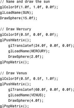
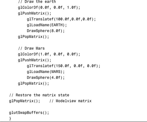
In PLANETS, the glInitNames function initializes and clears the name stack, and glPushName pushes 0 on the stack to put at least one entry on the stack. For the sun and each planet, we call glLoadName to name the object or objects about to be drawn. This name, in the form of an unsigned integer, is not pushed on the name stack but rather replaces the current name on top of the stack. Later, we discuss keeping an actual stack of names. For now, we just replace the top name of the name stack each time we draw an object (the sun or a particular planet).
Working with Selection Mode
As mentioned previously, OpenGL can operate in three different rendering modes. The default mode is GL_RENDER, in which all the drawing actually occurs onscreen. To use selection, we must change the rendering mode to selection by calling the OpenGL function:
glRenderMode(GL_SELECTION);
When we actually want to draw again, we use the following call to place OpenGL back in rendering mode:
glRenderMode(GL_RENDER);
The third rendering mode is GL_FEEDBACK, discussed later in this chapter.
The naming code in Listing 12.1 has no effect unless we first switch the rendering mode to selection mode. Conveniently, you call the same function to render the scene in both GL_RENDER mode and GL_SELECTION mode, as we have done here.
Listing 12.2 provides the GLUT callback code triggered by the clicking of the left mouse button. This code checks for a left button click and then forwards the mouse coordinates to ProcessSelection, which processes the mouse click for this example.
Listing 12.2. Code That Responds to the Left Mouse Button Click
///////////////////////////////////////////////////////////
// Process the mouse click
void MouseCallback(int button, int state, int x, int y)
{
if(button == GLUT_LEFT_BUTTON && state == GLUT_DOWN)
ProcessSelection(x, y);
}
The Selection Buffer
The selection buffer is filled with hit records during the rendering process. A hit record is generated whenever a primitive or collection of primitives is rendered that would have been contained in the viewing volume. Under normal conditions, this is simply anything that would have appeared onscreen.
The selection buffer is an array of unsigned integers, and each hit record occupies at least four elements of the array. The first array index contains the number of names that are on the name stack when the hit occurs. For the PLANETS example (Listing 12.1), this is always 1, because we never really push anything else on top of the name stack. The next two entries contain the minimum and maximum window z coordinates of all the vertices contained by the viewing volume since the last hit record. This value, which ranges [0,1], is scaled to the maximum size of an unsigned integer for storage in the selection buffer. The fourth entry is the bottom of the name stack. If more than one name appears on the name stack (indicated by the first index element), they follow the fourth element. This pattern, illustrated in Figure 12.1, is then repeated for all the hit records contained in the selection buffer. We explain why this pattern can be useful when we discuss picking.
Figure 12.1. Hit record for the selection buffer.

The format of the selection buffer gives you no way of knowing how many hit records you need to parse. The selection buffer is not actually filled until you switch the rendering mode back to GL_RENDER. When you do this with the glRenderMode function, the return value is the number of hit records copied.
Listing 12.3 shows the processing function called when a mouse click occurs for the PLANETS sample program. It shows the selection buffer being allocated and specified with glSelectBuffer. This function takes two arguments: the length of the buffer and a pointer to the buffer itself. You must make sure that you allocate enough elements ahead of time to contain all your hit records. If you do not, the call to glRenderMode will return –1 and the buffer contents will be invalid.
Listing 12.3. Function to Process the Mouse Click


Picking
Picking occurs when you use the mouse position to create and use a modified viewing volume during selection. When you create a smaller viewing volume positioned in your scene under the mouse position, only objects that would be drawn within that viewing volume generate hit records. By examining the selection buffer, you can then see which objects, if any, were clicked on by the mouse.
The gluPickMatrix function is a handy utility that creates a matrix describing the new viewing volume:
void gluPickMatrix(GLdouble x, GLdouble y, GLdouble width,
GLdouble height, GLint viewport[4]);
The x and y parameters are the center of the desired viewing volume in OpenGL window coordinates. You can plug in the mouse position here, and the viewing volume will be centered directly underneath the mouse. The width and height parameters then specify the dimensions of the viewing volume in window pixels. For clicks near an object, use a large value; for clicks next to the object or directly on the object, use a smaller value. The viewport array contains the window coordinates of the currently defined viewport. You can easily obtain this information by calling
glGetIntegerv(GL_VIEWPORT, viewport);
Remember, as discussed in Chapter 2, “Using OpenGL,” that OpenGL window coordinates are the opposite of most systems’ window coordinates with respect to the way pixels are counted vertically. Note in Listing 12.3, we subtract the mouse y coordinate from the viewport’s height. This yields the proper vertical window coordinate for OpenGL:
gluPickMatrix(xPos, viewport[3] - yPos + viewport[1], 2,2, viewport);
To use gluPickMatrix, you should first save the current projection matrix state (thus saving the current viewing volume). Then call glLoadIdentity to create a unit-viewing volume. Calling gluPickMatrix then translates this viewing volume to the correct location. Finally, you must apply any further perspective projections you may have applied to your original scene; otherwise, you won’t get a true mapping. Here’s how it’s done for the PLANETS example (from Listing 12.3):

In this segment, the viewing volume is saved first. Then the selection mode is entered, the viewing volume is modified to include only the area beneath the mouse cursor, and the scene is redrawn via a call to RenderScene. After the scene is rendered, we call glRenderMode again to place OpenGL back into normal rendering mode and get a count of generated hit records.
In the next segment, if a hit occurred (for this example, there is either one hit or none), we pass the entry in the selection buffer that contains the name of the object selected or our ProcessPlanet function. Finally, we restore the projection matrix (thus, the old viewing volume is restored) and switch the active matrix stack back to the modelview matrix, which is usually the default:
// If a single hit occurred, display the info.
if(hits == 1)
ProcessPlanet(selectBuff[3]);
// Restore the projection matrix
glMatrixMode(GL_PROJECTION);
glPopMatrix();
// Go back to modelview for normal rendering
glMatrixMode(GL_MODELVIEW);
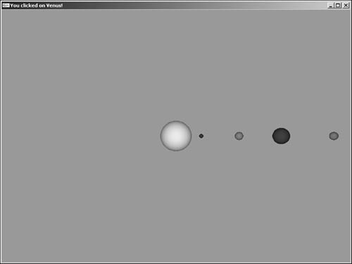
The ProcessPlanet function simply displays a message in the window’s caption telling which planet was clicked. This code is not shown because it is fairly trivial, consisting of no more than a switch statement and some glutSetWindowTitle function calls.
The output from PLANETS is shown in Figure 12.2, where you can see the result of clicking the second planet from the sun.
Figure 12.2. Output from PLANETS after a planet is clicked.
Although we don’t go into any great detail here, it is worth discussing briefly the z values from the selection buffer. In the PLANETS example, each object or model was distinct and off alone in its own space. What if you apply this same method to several objects or models that perhaps overlap? You get multiple hit records! How do you know which one the user clicked? This situation can be tricky and requires some forethought. You can use the z values to determine which object was closest to the user in viewspace, which is the most likely object that was clicked. Still, for some shapes and geometry, if you aren’t careful, it can be difficult to sort out precisely what the user intended to pick.
Hierarchical Picking
For the PLANETS example, we didn’t push any names on the stack, but rather just replaced the existing one whenever a new object was to be rendered. This single name residing on the name stack was the only name returned in the selection buffer. We can also get multiple names when a selection hit occurs, by placing more than one name on the name stack. This capability is useful, for instance, in drill-down situations when you need to know not only that a particular bolt was selected, but also that it belonged to a particular wheel, on a particular car, and so forth.
To demonstrate multiple names being returned on the name stack, we stick with the astronomy theme of our previous example. Figure 12.3 shows two planets (okay, so use a little imagination)—a large blue planet with a single moon and a smaller red planet with two moons.
Figure 12.3. Two planets with their respective moons.

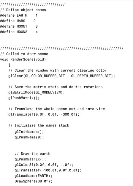
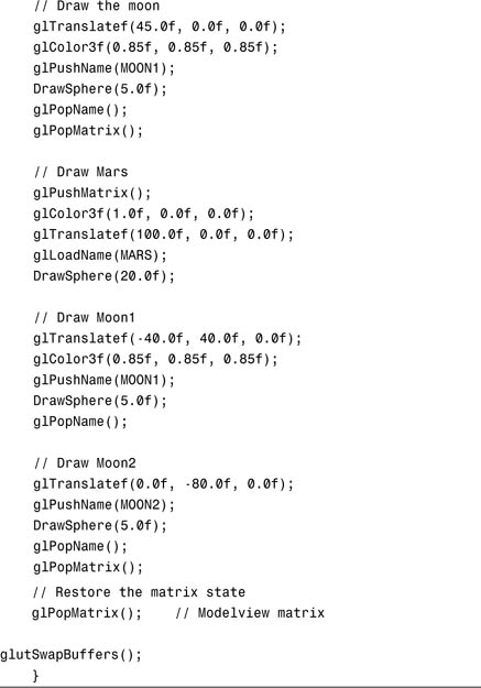
Rather than just identify the planet or moon that is clicked, we want to also identify the planet that is associated with the particular moon. The code in Listing 12.4 shows our new rendering code for this scene. We push the names of the moons onto the name stack so that it contains the name of the planet as well as the name of the moon when selected.
Listing 12.4. Rendering Code for the MOONS Sample Program
Now in our ProcessSelection function, we still call the ProcessPlanet function that we wrote, but this time, we pass the entire selection buffer:
// If a single hit occurred, display the info.
if(hits == 1)
ProcessPlanet(selectBuff);
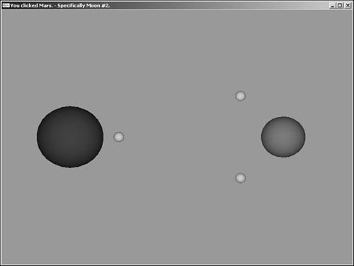
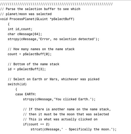
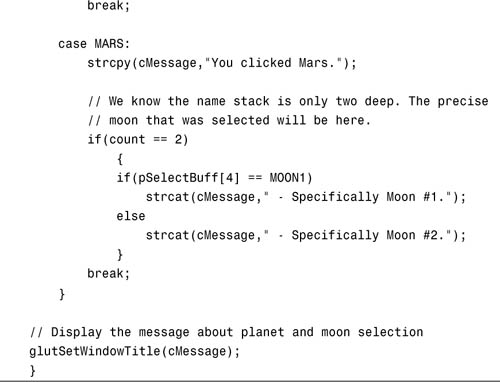
Listing 12.5 shows the more substantial ProcessPlanet function for this example. In this instance, the bottom name on the name stack is always the name of the planet because it was pushed on first. If a moon is clicked, it is also on the name stack. This function displays the name of the planet selected, and if it was a moon, that information is also displayed. Sample output is shown in Figure 12.4.
Figure 12.4. Sample output from the MOONS sample program.
Listing 12.5. Code That Parses the Selection Buffer for the MOONS Sample Program
Feedback
Feedback, like selection, is a rendering mode that does not produce output in the form of pixels on the screen. Instead, information is written to a feedback buffer indicating how the scene would have been rendered. This information includes transformed vertex data in window coordinates, color data resulting from lighting calculations, and texture data—essentially everything needed to rasterize the primitives.
You enter feedback mode the same way you enter selection mode, by calling glRenderMode with a GL_FEEDBACK argument. You must reset the rendering mode to GL_RENDER to fill the feedback buffer and return to normal rendering mode.
The Feedback Buffer
The feedback buffer is an array of floating-point values specified with the glFeedbackBuffer function:
void glFeedbackBuffer(GLsizei size, GLenum type, GLfloat *buffer);
This function takes the size of the feedback buffer, the type and amount of drawing information wanted, and a pointer to the buffer itself.
Valid values for type appear in Table 12.1. The type of data specifies how much data is placed in the feedback buffer for each vertex. Color data is represented by a single value in color index mode or four values for RGBA color mode.
Table 12.1. Feedback Buffer Types

Feedback Data
The feedback buffer contains a list of tokens followed by vertex data and possibly color and texture data. You can parse for these tokens (see Table 12.2) to determine the types of primitives that would have been rendered. One limitation of feedback occurs when using multiple texture units. In this case, only texture coordinates from the first texture unit are returned.
Table 12.2. Feedback Buffer Tokens
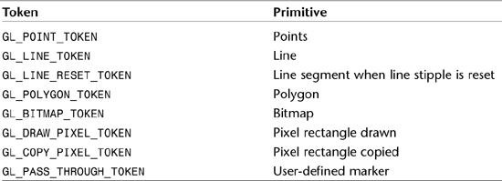
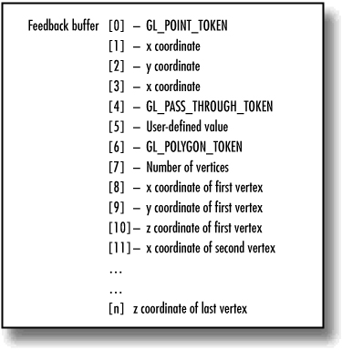
The point, bitmap, and pixel tokens are followed by data for a single vertex and possibly color and texture data. This depends on the data type from Table 12.1 specified in the call to glFeedbackBuffer. The line tokens return two sets of vertex data, and the polygon token is immediately followed by the number of vertices that follow. The user-defined marker (GL_PASS_THROUGH_TOKEN) is followed by a single floating-point value that is user defined. Figure 12.5 shows an example of a feedback buffer’s memory layout if a GL_3D type were specified. Here, we see the data for a point, token, and polygon rendered in that order.
Figure 12.5. A sample memory layout for a feedback buffer.
Passthrough Markers
When your rendering code is executing, the feedback buffer is filled with tokens and vertex data as each primitive is specified. Just as you can in selection mode, you can flag certain primitives by naming them. In feedback mode, you can set markers between your primitives, as well. You do so by calling glPassThrough:
void glPassThrough(GLfloat token);
This function places a GL_PASS_THROUGH_TOKEN in the feedback buffer, followed by the value you specify when calling the function. This process is somewhat similar to naming primitives in selection mode. It’s the only way of labeling objects in the feedback buffer.
A Feedback Example
An excellent use of feedback is to obtain window coordinate information regarding any objects you render. You can then use this information to place controls or labels near the objects in the window or other windows around them.
To demonstrate feedback, we use selection to determine which of two objects on the screen has been clicked by the user. Then we enter feedback mode and render the scene again to obtain the vertex information in window coordinates. Using this data, we determine the minimum and maximum x and y values for the object and use those values to draw a focus rectangle around the object. The result is graphical selection and deselection of one or both objects.
Label the Objects for Feedback
Listing 12.6 shows the rendering code for our sample program SELECT. Don’t confuse this example with a demonstration of selection mode! Even though selection mode is employed in our example to select an object on the screen, we are demonstrating the process of getting enough information about that object—using feedback—to draw a rectangle around it using OpenGL lines in a 2D orthographic projection. Notice the use of glPassThrough to label the objects in the feedback buffer, right after the calls to glLoadName to label the objects in the selection buffer. Because these functions are ignored when the render mode is GL_RENDER, they have an effect only when rendering for selection or feedback.
Listing 12.6. Rendering Code for the SELECT Sample Program
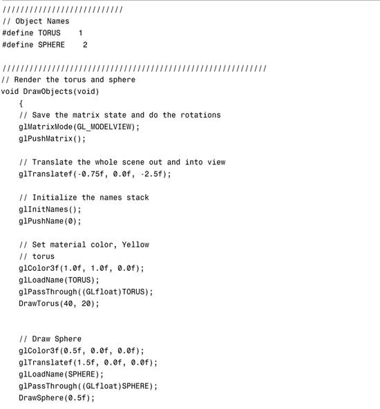
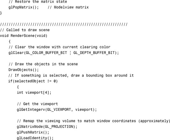
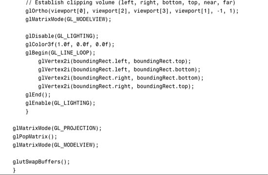
For this example, the rendering code is broken into two functions: RenderScene and DrawObjects. RenderScene is our normal top-level rendering function, but we have moved the actual drawing of the objects that we may select to outside this function. The RenderScene function draws the objects, but it also draws the bounding rectangle around an object if it is selected. selectedObject is a variable we will use in a moment to indicate which object is currently selected.
Step 1: Select the Object
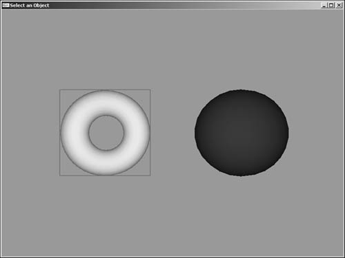
Figure 12.6 shows the output from this rendering code, displaying a torus and sphere. When the user clicks one of the objects, the function ProcessSelection is called (see Listing 12.7). This is similar to the selection code in the previous two examples (in Listings 12.3 and 12.5).
Figure 12.6. Output from the SELECT program after the sphere has been clicked.
Listing 12.7. Selection Processing for the SELECT Sample Program


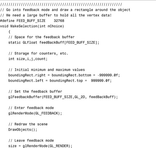
Step 2: Get Feedback on the Object
Now that we have determined which object was clicked (we saved this in the selectedObject variable), we set up the feedback buffer and render again in feedback mode. Listing 12.8 shows the code that sets up feedback mode for this example and calls DrawObjects to redraw just the torus and sphere scene. This time, however, the glPassThrough functions put markers for the objects in the feedback buffer. Similar to the case of the selection buffer, if you do not allocate enough space for all the data when you call glFeedbackBuffer, glRenderMode will return –1 indicating an error.
Listing 12.8. Load and Parse the Feedback Buffer
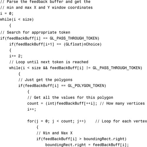
When the feedback buffer is filled, we search it for GL_PASS_THROUGH_TOKEN. When we find one, we get the next value and determine whether it is the one we are looking for. If so, the only task that remains is to loop through all the polygons for this object and get the minimum and maximum window x and y values. These values are stored in the boundingRect structure and then used by the RenderScene function to draw a focus rectangle around the selected object.
Summary
Selection and feedback are two powerful features of OpenGL that enable you to facilitate the user’s active interaction with a scene. Selection and picking are used to identify an object or region of a scene in OpenGL coordinates rather than just window coordinates. Feedback returns valuable information about how an object or a primitive is actually drawn in the window. You can use this information to implement features such as annotations or bounding boxes in your scene.
The reader should note that the features in this chapter are typically implemented in software (the driver), even for hardware accelerated OpenGL implementations. This means that rendering in selection mode, for example, will be very slow compared to hardware rendering. A common means of accounting for this is to render lower resolution “proxies,” and render only objects that can be clicked on when performing selection. There are more advanced means of determining object selection that may be preferable for real-time picking. Some of the 3D math books in Appendix A would be a good place to start. Using the techniques in this chapter makes adding this kind of functionality to your application fairly straightforward. You may also find that even with software rendering, the response time from mouse click may be more than fast enough for most purposes.