
Hour 8. Character Modeling
What You’ll Learn in This Hour:
![]() How to prepare for creating a character in Maya
How to prepare for creating a character in Maya
![]() How to create a low polygon character
How to create a low polygon character
![]() What to consider when creating characters
What to consider when creating characters
![]() How to identify problem areas
How to identify problem areas
Nearly all modern visual-effects-laden films and shows contain at least some character animation. From talking fuzzy animals to drooling insects, the television and film VFX markets rely heavily on modelers who can bring designs to life in 3D. This means that for your purposes as a CG artist, familiarity with the character-creation process is crucial. If you are planning on moving further down the character-modeling path, this Hour will be helpful for you to start getting accustomed to common considerations with CG character models.
Note: Working A-Head
We will go over common issues in character modeling that cover both the head and the body, although there are enough issues to discuss about head and face modeling to fill an entire book. Remember to use the concepts and exercises in this book as a jumping-off point for further study in CG and in Maya.
In this Hour, you will encounter the most common issues surrounding character modeling and learn how to overcome them. You will set up a scene in a way that allows for easy character creation and accurate modeling from a design. You will also learn about modeling considerations as they pertain to a production. Like most of the CG disciplines, character modeling is subject to personal workflows. Therefore, as you read this Hour, take note of the concepts that seem to come naturally to you, and those that are a little more difficult, so that in your personal exercises later on you can focus on finding your own way to achieve the goals explained here.
Character Model Basics
With a little bit of polygon modeling experience, you can pretty much intuit the process of creating a character model. The literal acts of extruding, adding edge loops, and merging vertices are all the same when you are modeling a character as when you are modeling a cell phone or a car. However, because characters are almost always meant to deform and move onscreen, certain important considerations must be made to ensure successful character modeling.
Working From Designs
One of the first considerations you have to make is whether you are going to be working from drawn character designs. If so, it is imperative that you have those drawings imported and arranged in your scene in a way that helps you get the 3D model as accurate as possible. Because it is common to work from designs, Maya makes it easy to get your images into the scene. Figure 8.1 shows how close to a design it is possible to create a character.

FIGURE 8.1 This finished character model looks very close to the design because we were careful to use all of Maya’s available tools.
To begin, we must first create planes that will serve as guides in 3D space as to where our geometry is supposed to be placed. This is commonly achieved in one of two ways: using camera image planes or using polygonal planes with the designs as a texture. The first way involves importing the image as a background in your panel—otherwise known as an “image plane” (more in Hour 22, “Working with Film”). The advantages to this method are that Maya automatically retains the aspect ratio of your drawing, so an extra step is removed. The downside is that to move, rotate, or scale these planes, you must do so through the image plane’s attributes in the Attribute Editor, which can be cumbersome when you are in the middle of modeling the character. Even with this drawback, the camera image planes are quicker and easier to create than polygonal planes, so we will use them.
First, we must locate our designs and make sure they have been created correctly. We just need to make sure that the front and side views’ images line up perfectly. Navigate to this Hour’s source files directory and open up design_Ortho.jpg (see Figure 8.2).

FIGURE 8.2 Notice how this design was created with the character perfectly lined up in both the front and side views. This makes it so that we have the most accurate guide and the easiest time matching the design.
You can clearly see that the front and side views line up correctly. So in order to use these designs, we must load them as image planes on their respective cameras. Open Maya, and in any panel, go to Layouts, Saved Layouts, Four Panes. This will reset your panel layout to the well-known standard layout shown in Figure 8.3.

Next, we load the images as the image planes for the front and side cameras. In the front panel, go to View, Image Plane, Import Image.... Navigate to this Hour’s source files and choose image_Front.jpg. The image has been cropped for the front view. In the Attribute Editor (which should open automatically when you create the image plane), one of the very first sliders is the Alpha Gain. This controls how “see-through” your image planes are. Set the Alpha Gain to .5 for the front image plane as well as the side image plane when you are done importing it. The properly loaded image is shown in Figure 8.4.
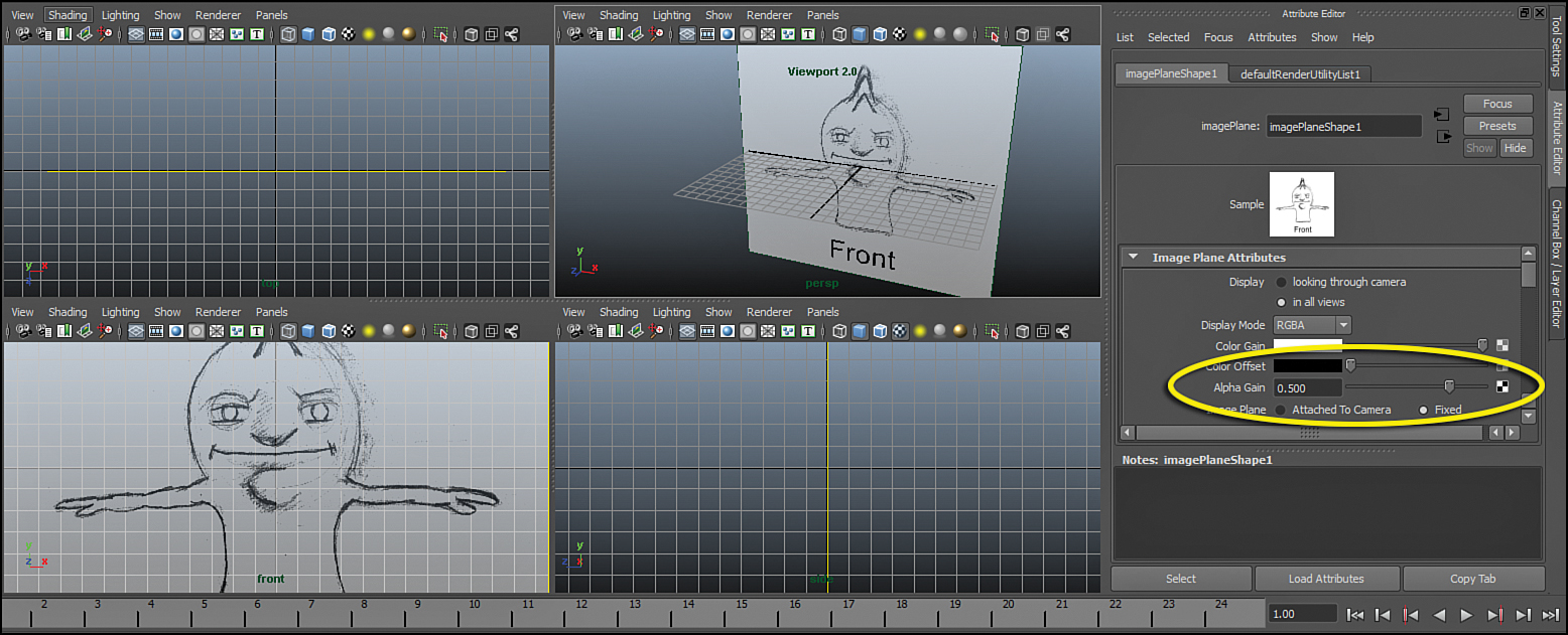
FIGURE 8.4 The front view of the design loaded as an image plane into the front panel. The alpha gain (circled) is set to .5. Notice also that transparency is working correctly in the Persp panel with Viewport 2.0 set as our renderer.
Note: Viewport 2.0
We are going to set our Persp panel to render with Viewport 2.0. This panel render engine has some quality features that give us great options for viewing models really beautifully in panel (even before rendering). In this case, however, we need Viewport 2.0 simply for the fact that it renders transparent image planes in the Perspective cameras correctly. In the Persp panel, go to Renderer, Viewport 2.0.
Now do the same for the side panel. Go to View, Image Plane, Import Image... one more time and find the image_Side.jpg file. Once it is loaded, you can see in the Persp panel that both images are placed at the world origin, ready for your use, as shown in Figure 8.5.
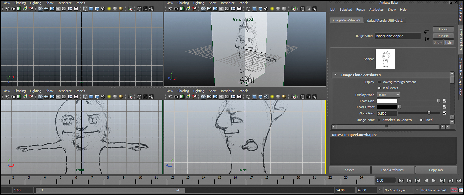
FIGURE 8.5 The two image planes loaded into Maya. Notice how they maintain their aspect ratio by default, which is an extra step you have to take care of if you were to create polygon planes and arrange them yourself in this manner.
We will want to move the image planes so they are not in the way of the character when we start to model him. Select the front image plane and press Ctrl+A to bring up the Attribute Editor. If you scroll down the attributes, you will see a section called Placement Extras. You can resize your image plane and move it around the scene using these attributes. The Image Center attribute controls where the plane is placed. We want to move the image plane backward so it will be behind the model, so change the value in the far-right box next to Image Center (this is the Z value, even though it is not labeled) to –8. Select the side image plane and make the X value (first box) in its Image Center attribute –12. Figure 8.6 shows the planes with their correct positions.

FIGURE 8.6 The image planes as they should be, lined up and ready to guide us as we create our geometry.
Tip: Seeing Three Boxes? It’s XYZ!
Any time Maya has three inputs or attributes next to each other with no labeling, it is assumed that the three attributes control the X, Y, and Z values of whatever node you are editing. Be warned, though: Sometimes direction is relative, like in the sense of the Front and Side cameras, where Z is always away from camera, and might not line up with the Z axis in world space.
Once that is completed, we are almost ready to start creating geometry the same way we did with the hammer in Hour 4, “Modeling with Polygonal Geometry.” There are just a few more steps to take to make sure we are going to have the most efficient workflow when modeling. Create a polygon sphere by going to Create, Polygons, Sphere. Click anywhere in the front panel and press the 5 key to shade the objects. As you can see, the sphere is opaque and we cannot see our image planes through it. To see through objects in a panel, click on (in your panel) Shading, X-ray. RMB drag on the sphere and choose vertex. With the vertices highlighted, it’s easy to see how intuitive and simple it will be to line up the polygons with details in the designs.
Note: Image Specifics
The importance of having accurate, well-drawn orthographic images cannot be overstated. If you try to use this method of creating image planes with designs that were not drawn from straight-on and side angles, your results will be highly skewed. It is also imperative that the images share at least one of the same dimensions—be it width or height—so that scaling the images (using the Width and Height attributes) can be done uniformly. The best practice is to combine the two images into one image to line them up, and then crop and save the two views out separately, retaining the image size.
Using Symmetry in Modeling
We’re nearly ready to start modeling. Before we begin, we need to set up our model so that when we work on one side of the character, the other side will update as well. There are a wide variety of ways to do this, so I will show you the way that works the simplest—a “mirrored instance.”
Note: Duplicates and Instances
The main difference between duplicating an object and instancing an object is that the instance will continue to update with modifications until it is converted into a separate object. Think about an instance as a duplicate with a continuous link to the other object, always updating and adjusting as you work. This link even persists if you delete history on both objects.
To create a mirrored instance, we are going to start with a single polygon. Create a polygon plane by clicking Create, Polygon Primitives, Plane and then the options box ![]() . In the options box that appears, make sure the width divisions and height divisions are both set to 1 and then click Create. Now in the Persp panel, RMB drag and select the two vertices on the left side of the side image plane (the two vertices in negative X space) so that you can move them to the axis, as in Figure 8.7.
. In the options box that appears, make sure the width divisions and height divisions are both set to 1 and then click Create. Now in the Persp panel, RMB drag and select the two vertices on the left side of the side image plane (the two vertices in negative X space) so that you can move them to the axis, as in Figure 8.7.

We are going to move these two vertices to the center of the world axis. Press W to switch to the Move tool. Now, holding down the X key makes it so that Maya will snap a vertex to the gridlines (the V key snaps to vertices, and the C key snaps to curves). With the X key pressed, move these two vertices along the X axis until they snap to the center (they will be aligned with the side panel’s image plane). Figure 8.8 shows the vertices in the correct position.

Now we will instance this geometry. Press F8 to return to object mode or RMB drag on the plane and choose “object.” Go to Edit, Duplicate Special and then the options box ![]() . In the options box, change “Geometry type” to “Instance,” and in the first value box (the X value) for “Scale,” enter –1 (remember that when you see three boxes, they are X, Y, and Z). Leave the rest of the settings at default and hit “Duplicate Special”. A new plane will mirror across the X axis (the result of scaling it by –1), and it is an instance of our first plane. The two planes are now linked together, as shown in Figure 8.9, and all of the edits and modifications you do to the geometry of one will be applied to both simultaneously.
. In the options box, change “Geometry type” to “Instance,” and in the first value box (the X value) for “Scale,” enter –1 (remember that when you see three boxes, they are X, Y, and Z). Leave the rest of the settings at default and hit “Duplicate Special”. A new plane will mirror across the X axis (the result of scaling it by –1), and it is an instance of our first plane. The two planes are now linked together, as shown in Figure 8.9, and all of the edits and modifications you do to the geometry of one will be applied to both simultaneously.

FIGURE 8.9 The final result of mirrored instancing. The two planes are instanced objects; therefore, when we make adjustments, and even add geometry onto these objects, they will give us a symmetrical model.
Note: Negative Transforms and Normals
Remember normals? They were mentioned in the Hour 4 quiz, and are basically the “direction” that Maya considers a polygon to be “facing.” If you perform a Modify, Freeze Transformations on a piece of geometry with negative scale, it will flip the normal so that the surface is facing inward. This is a problem for UV’ing and rendering, and even some other effects that rely on face normals. Do not Freeze Transformations on a piece of mirrored geometry; we will perform the necessary steps to make sure we can combine the instanced objects correctly.
Starting a Model
We will begin by making some extrusions of this plane, working in the side and front panels to take advantage of the design we have.
Start by selecting the vertices and lining them up with the forehead in the side panel (see Figure 8.10).

FIGURE 8.10 The first polygon is now lined up with the forehead area of our design. Get it close; there’s no such thing as perfect at this stage. Remember to select both vertices when lining this up in the side panel.
Next, select the top edge and extrude it once (in the Polygons menu set, click Edit Mesh, Extrude), working in the side panel to line up the geometry with the design (see Figure 8.11).

Continue extruding the geometry until you have gone around the entire circumference of the character in the side panel. To connect the last two faces, line up the vertices as best you can in the side panel and then switch to the Persp panel. Select two vertices that are supposed to be connected and then select Edit Mesh, Merge. They should “weld” together.
Tip: Selecting Both Vertices
When you are selecting the vertices in the side panel, be very careful to not select single vertices. Some vertices are lined up with each other, so in the side panel it will look like there is only one. The easiest way to make sure you select both while you are doing this step is to drag small selection boxes around both vertices instead of LMB clicking.
Note: Extruding in the Right Direction
The Extrude tool will show you a manipulator when you engage the tool that corresponds to the direction of the face. If you are working only in the side panel, you don’t have to worry about the polygons moving off of the center of the grid, but if you are working in the Persp panel, be careful: It is easy to accidentally move a face when extruding in the wrong direction.
Edge Loops
From Hour 4 you learned that edge loops are a series of continuous edges in a polygonal model. Edge loops are much more important in character modeling, because most of the time we are going to subdivide our mesh at render time and the results need to be predictable. Having good control over your edge loops means being able to have the “flow” of the model follow natural lines instead of fighting against them. A good example is the muscles of the arms; you would have a hard time really defining a nice bicep shape without edge loops that follow the curve of that muscle. Another instance when edge loop control is very necessary is when we have circular shapes in our mesh, such as mouths, eye sockets, and nostrils. It is common to draw a few edge loops on your design to give you a guide as to where the detail needs to go. Select the front panel’s image plane, go into the Attribute Editor, and then replace the image with image_Front_Loops.jpg, as seen in Figure 8.12.

FIGURE 8.12 The updated front view image with a few important edge loops drawn over. We will integrate these edge loops as we work.
Let’s create the edge loop that encircles the eye. One way is to create some polygons in the area of the eye and then use the Interactive Split tool and extrude to edit the polygons into shape. Instead, we will purposefully create the edge loops explicitly so that we know where they will be. Extrude the edges down the nose until your polygon is lined up with the edge loops drawn on the front image plane. Select the edge that is closest to the inside of the eye, as shown in Figure 8.13.
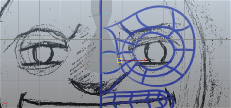
FIGURE 8.13 The edge that we are going to start with to create the edge loop that will encircle the eye socket.
Note: Setting Up Polygon Display
We want to be able to see through the polygons we are manipulating so that we can see the design while we work. Turn on X-ray shading by clicking on the Shading menu in your front and side panels and clicking on X-Ray. Make sure you are in shaded mode as well by pressing 5 while your mouse is within the panel. You should now be able to see through the polygons.
Extrude the edge in the front panel two times toward the eye socket (see Figure 8.14).

Move the vertices of the extruded edges to be in line with the eye socket, like I did in Figure 8.15.

Now extrude the edge all the way around the eye socket and then weld the vertices at the end when you are done (see Figure 8.16). Eight to ten extrusions is enough.

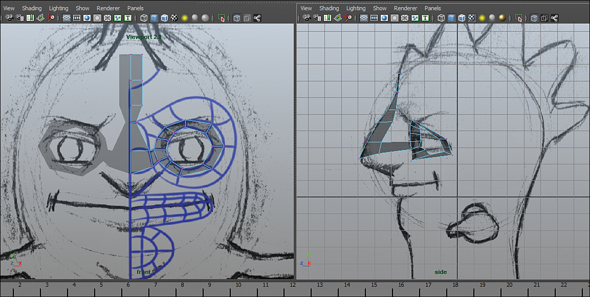
Now we must work simultaneously in the front and the side panels to move the vertices in the Z direction and line them up with the design in the side panel. Move them into place, as shown in Figure 8.17.
Continue Refining Your Model
Continue extruding and positioning faces to create the rest of the character’s body geometry. Leave the arms out for now. You may want to make use of the Append to Polygon tool instead of merging vertices. To use this tool, select it by going to Edit Mesh, Append to Polygon Tool. Once it is active, select the open edge you would like to close. Triangular manipulators will appear on the edges in the mesh that you can select to create the new polygon. Click on any of them to create the new polygon; then press Enter to finish the tool. Once you have created the rough geometry for the entire character, you can go back and use the Interactive Split tool to redefine the edge loops. Look for areas where the edges are getting crossed and disorganized. You can use the Interactive Split tool to make some splits, and then delete the old edges to make things look like they are working better. In general, try to get the geometry evenly spaced and the edge loops looking smooth in all directions. As you get more practice, it becomes easier to predict how your geometry will turn out.
Multi-Edged Intersections: Poles
You may notice that you are getting many “poles” in your geometry. A pole is any vertex that is at the intersection of more than four edges. A certain number of poles is unavoidable because of the different elements you need to fit together in a single mesh. A character that has many circular edge loops close together is especially prone to having poles. Even our character has poles in his face near the eye socket. We do want to try to reduce the number of poles as much as possible because they are another problem for smoothing at render time. And we definitely want to try to get rid of poles in any place that is going to have a lot of deformation happening; they will introduce smoothing errors. Figure 8.18 shows some poles in our model.

FIGURE 8.18 Poles are anywhere that more than four edges meet. Maya doesn’t know how to subdivide these areas nicely.
Remember from Hour 4 we talked about how it is ideal to have three- and four-sided faces in our models? One way to reduce the number of poles you have from the outset is to try as hard as possible to make sure you only have four-sided faces, and that your edge loops are as long as possible. This will help ensure you are not creating tangled nests of polygons. Chances are your edge loops are terminating at poles; therefore, if you double-click on an edge, follow the selected edge loop to its ends to discover poles.
A place where poles are guaranteed to appear is anywhere a face is extruded from a plane. The vertices already have four edges intersecting at them, and you are essentially adding one more. If you think of the most low-poly bipedal shape possible, you will see that poles are unavoidable wherever appendages are extruded (see Figure 8.19).
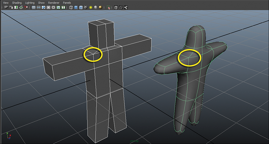
FIGURE 8.19 This very simple representation of a bipedal character illustrates how some poles are unavoidable. Even when smoothed (right), the poles remain. Keeping poles to a minimum is the mark of a good character modeler.
Adding the Arms
Seeing as having a few poles is unavoidable, we’re going to extrude the polygons that make up the arms from the open edges on his side. If you want to start from the same point as I have, open character_Mid.ma in this Hour’s source files. Go into the Edges component mode and double-click on the open edge loop on his sides. Use the Edit Mesh, Extrude tool to extrude his arms all the way to the wrists. This time, we’re going to add detail using the Insert Edge Loop tool to give ourselves detail where we need it. Select Edit Mesh, Insert Edge Loop and click a few times along the arm, putting at least three loops near the elbow. When that is done, you can go into the vertex component mode and make the adjustments you need to get the vertices to line up with the design.
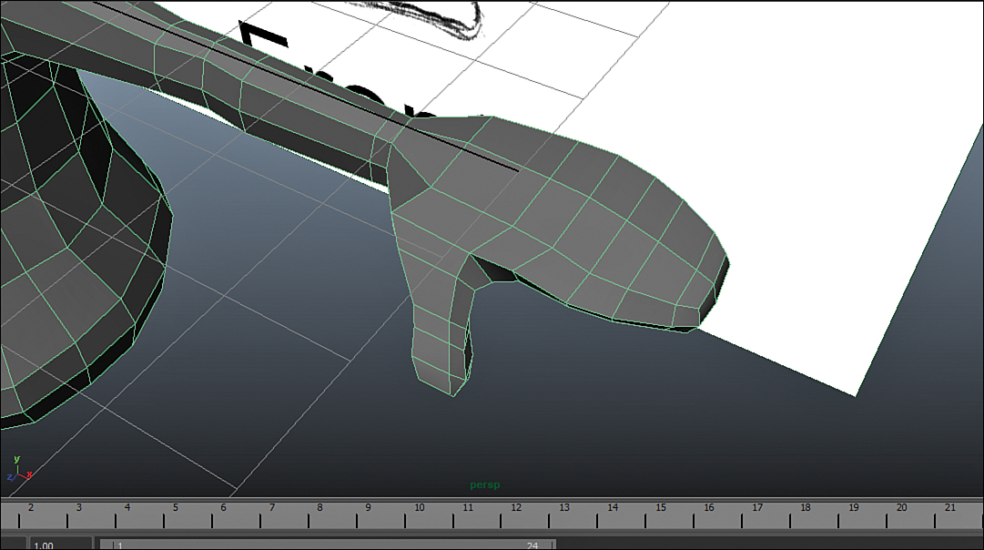
This character was designed with “mitten hands” so that it would not be too challenging to try to get the hands in place. Keep extruding, appending, and adjusting vertices to get the hands in place, as shown in Figure 8.20.
Note: Legs Cover the Real Center
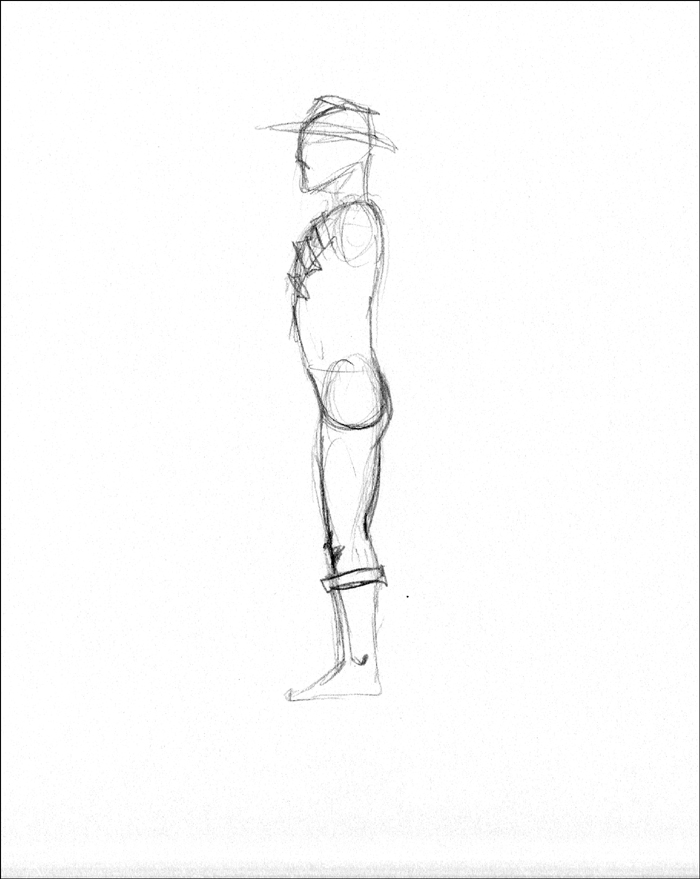
Notice how our character’s arms are basically not visible in the side panel’s image plane. Because they don’t block any geometry they are visible in the side drawing. Legs, however, do block crucial information—where the center edge loop goes from front to back through the groin area. On most side-view designs, the center edge loop is drawn even though it should be blocked by the leg (see Figure 8.21).
Low-Poly Workflow
As we move ahead, we should start thinking about the workflow that this character is going to go through. One of the more popular workflows is to export your geometry in a low-polygon state to a piece of 3D sculpting software to add details and then apply those details to the low poly at render time with something called a “displacement map.” This workflow saves a lot of scene overhead because Maya does not handle millions of polygons in panel very well, nor could you possibly animate a character that had that much detail.
Working “low poly” means that you aren’t necessarily trying to model detailed parts of the character into the geometry. This is particularly true for details such as buttons on a shirt, belts, arm bands, and so on. These small details would be better suited to be separate objects that you either constrain or rig to move along with the character geometry rather than being built into the single character mesh. A good rule of thumb is that anything that is “skin tight” can be a part of the character model, and anything that is not should be a separate object. Just imagine how hard it would be to have good edge loops if you had to add really tiny details to a low-poly object.
The last advantage to a low-poly workflow is the fact that you are simply dealing with fewer polygons. When we get to rigging and skinning this character, you will see that having fewer polygons to deal with is extremely advantageous. Particularly when we are creating shapes for the eyelids and mouth for animation, our low-poly character will be very simple to set up to take on some very dynamic shapes.
Problem Areas
Characters have some areas that traditionally can give us a lot of trouble. Therefore, you need to know what these areas are and some good methods for keeping out of trouble.
Inside the Mouth
Inside the mouth can be tricky to model because it is hidden by other geometry, and you have to decide what kind of mouth interior you want before you go about creating it. It can be a good idea to create a hollow mouth interior and have separate geometry for the teeth and tongue to avoid the problems mentioned before concerning detail and edge loop efficiency. The mouth interior does not have to be very big; a common beginner mistake is to make the mouth large, but we won’t fall into that trap. Figure 8.22 shows a good-sized mouth interior.
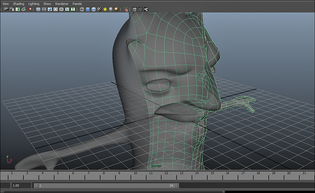
FIGURE 8.22 Our character with a hollow mouth added. We can add the teeth and tongue later if we wish.
Armpits and Shoulders
We created the arms by extruding an open edge loop on the side of the body, which created four poles. For our purposes, this shouldn’t work out to be too disruptive in either the animation or the smoothing processes, but you should know anyway that armpits and shoulders are challenging. The reason they present such a challenge is that they have a very wide range of motion, and they take on very different shapes depending on if the arm is up, down, forward, or back. We create our character in T-pose (with arms perfectly out to the sides) because with most cartoon characters, this pose represents the middle of the range of motion. On some feature film rigs, the arms are modeled to be more relaxed, slightly lowered, and a little bit bent forward at the elbow. This is done because, in reality, our range of motion for most common tasks is very narrow. Because our character has very little armpit or shoulder definition, just a tiny bit of bulge on top and a little bit of indentation on the bottom of the arm will suffice. In Figure 8.23, the poles that were created on his arm area are shown, but there shouldn’t be problems with smoothing or deformation here.

FIGURE 8.23 The arms of our character are not so bulky or defined that we’ll run into deformation or smoothing problems with the poles that were created, but you should keep it in mind for future characters.
Hands
Our character’s hands do not have much detail, but with realistic characters with multiple fingers, the hands are a challenge. The issue is getting enough edges into the fingers to nicely define the shape, without having to terminate too many of those edges at the wrist and create nasty poles. Most hand models use the same extrusion we did for this character’s arms on each of the fingers, making it so the poles that would be created for the finger detail end up between the fingers and not all bunched up in the wrist.
Eyelids
Our character has very simple eyes with nice bulky eyelids. For characters with more realistic, thin eyelids, they are normally modeled closed so that by using rigging tools and deformers, they can be opened nicely. It is done this way because it is easier to rig an eye to open than it is to untangle the scrunched-up geometry of a closed eyelid and make it close nicely. Ours is modeled open solely because of the fact our character is cartoony, unrealistic, and, most importantly, low poly.
Elbows and Knees
These two areas are just like the armpits and shoulders in that they will either flatten out or get bunched up when deforming. Also, elbows and knees actually take on very different shapes (due to the bones changing position and pushing the skin out) when they are bent than when they are relaxed. We can use something called BlendShapes (described in Hour 15, “Making Diverse Shapes with BlendShapes”) to change the shape of the elbows and knees depending on whether they are bent or not. Therefore, to avoid problems, model the knees and elbows in their clearly relaxed poses, not something halfway, which might be intuitive to avoid problems.
Density
When you’re modeling characters, it’s common to be focused on the section you are working on, and only worry about the overall model density later on. However, it is a good practice to have an idea of how dense the geometry is going to be on your character before you begin. Certain areas need more density, or they will not behave correctly when they deform. This is why we added extra edge loops near the elbow of our character. To make very sure we get the exact shape we want out of him, go back in and add some more detail on his elbow, as seen in Figure 8.24. When it comes time to rig these elbows, I know we’ll have enough detail to get the results we want.

FIGURE 8.24 The elbows can be problem areas if you don’t have enough geometric detail, or density, in the areas where they deform.
Besides areas that are going to deform, you also want more density in areas that are going to get the most screen time. For this reason, the face and head are typically the densest regions on your character model. Taking a step back and looking at our character model proves this is true, even with cartoony characters, as you can see in Figure 8.25.
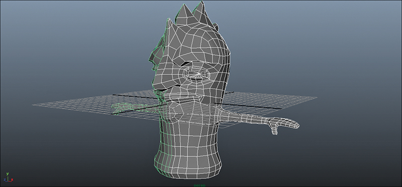
FIGURE 8.25 The detail is higher in the face than anywhere else because it will deform, but mostly because an audience spends the majority of their time watching the face!
The one other consideration for density is for any effect that relies on polygonal detail. Some particle systems generate particles per face, and if your mesh is too lopsided in detail, it can create some odd effects. Some third-party fur plugins generate hairs based on polygons as well; again, having far too much detail in one section and far too little in another can mean unpredictable results.
Smoothing
We discussed smoothing in Hour 4, and the same considerations apply with characters. In some ways, it’s more important to think about smoothing as you are working with characters, because as a character deforms in animation, the smoothing you apply will greatly affect how it looks in your final images.
Smoothing Reduces Detail
Remember that smoothing the geometry by tessellation does just that: It smooths! Wherever there are details that are not represented by enough polygons to really “define” it, you are going to lose that detail a bit when you smooth the mesh. Take a look at how the profile of the nose changes slightly when we press the 3 key and preview the smoothing, as shown in Figure 8.26.

FIGURE 8.26 The nose before and after smoothing. Notice how the profile changes when smoothing is applied.
When you are getting close to making your final adjustments to a model, previewing the smoothing is important. Keep a close eye on areas where the geometry is protruding or receding, because smoothing will reduce the contrast in these areas the most.
Deciding on Smoothing
The issues regarding what type of smoothing to use are the same with characters as they are with non-organic geometry.
Under most circumstances, if you are using Mental Ray to render (and not the Maya software renderer or a third-party choice), smooth your geometry with Mental Ray’s smooth mesh preview (by pressing 3 with geometry selected). This is when smoothing can happen as a last step before rendering.
In some rare cases, certain deformers, constraints, or miscellaneous nodes depend highly on the geometry and you will need to smooth your mode using the Mesh, Smooth command. Things such as toon lines depend on topology, and in order for them to follow the contour of the model, you will have to smooth the mesh using the Smooth command and not Mental Ray smooth mesh preview.
Tip: Adjusting the Smooth Mesh Preview
Unlike other inputs, the Smooth Mesh Preview settings are found in an object’s shape node. Open the Attribute Editor with an object selected (Ctrl+A) and select the shape node (normally the second tab from the left at the top of the Attribute Editor). Scroll down to the section labeled “Smooth Mesh,” and all of the attributes are available for you to change the preview to match your render settings or to be optimized for fast interaction.
Crease Edges
In Hour 4, we talked about using crease edges with polygonal geometry as a way to preserve sharp edges in your model when you smooth it. Find this tool under Edit Mesh, Crease Edges Tool. Crease edges only update interactively with Mental Ray’s smooth mesh preview. If you want to take advantage of crease edges, know that they will not update interactively when you use the Mesh, Smooth command. If you make adjustments to the creases, you must delete the polySmooth node or delete history on the model and apply the Smooth again.
Combining Geometry
Once you are ready to combine both sides of the geometry into one mesh, follow these steps. First, delete history on both models by pressing Alt+Shift+D with the objects selected. Then, with the objects still selected, go to Mesh, Combine. It will create a new object and a blank group node that represents the transforms of the old geometry. These will not be used for anything, so delete history again, and the extra nodes will be removed. Now, there’s a tricky thing happening right now: The center vertices are not welded together yet. It is quick to merge the vertices, but we’ll need to make sure they are all lying on the world center axis first. Switch to Vertex components mode and, in the top panel, select all of the vertices that run through the center of the model by dragging a selection box around them. Figure 8.27 shows the center vertices selected correctly.

With the W key pressed and held, LMB click in the panel and make sure your Move tool is set to “World” space (see Figure 8.28).

Go into the Move tool’s settings (Windows, Settings/Preferences, Tool Settings—or double-click the Move tool in the toolbox). Scroll down to the section called “Move Snap Settings” and uncheck “Retain component spacing.” This setting controls whether components you move are going to stay locked in their relative positions when you move them, or whether they will move absolutely. Now, with the center vertices still selected, hold the X key down and move the vertices on the X axis until they snap to the next gridline, and then move them back so they snap back to the center gridline. What you just did is moved all of the vertices to an adjacent gridline and snapped them to the grid and then moved them back into place. Now we know all of the center vertices are in the right position. Go to Edit Mesh, Merge, and the vertices will merge and close the center seam.
Tip: Double-Checking the Merge Worked
To make sure the merge vertices worked, you can always check to see if the number of vertices was reduced by half. To see the number of vertices you have selected, go to Display, Heads Up Display, Poly Count. Note the number of vertices it says you have selected (the far-right column) before you merge and after you merge. If you have followed the steps correctly, the number should be half of what you started with after you merge.
UVs Review
We are going to UV this character, which should be pretty straightforward. Also, he is symmetrical, and with characters it is better to not take advantage of symmetry. Characters seem a little bit more real with some asymmetry in their texture. To start from the finished model I am using, open character_Model_Finished.ma. Select the character, and in the Polygons menu set (F3), go to Create UVs, Cylindrical Mapping. Select all of the edges of the character, and in the UV Texture Editor (Windows, UV Texture Editor), go to Polygons, Sew UV Edges. Figure 8.29 shows the UV edges sewn correctly.
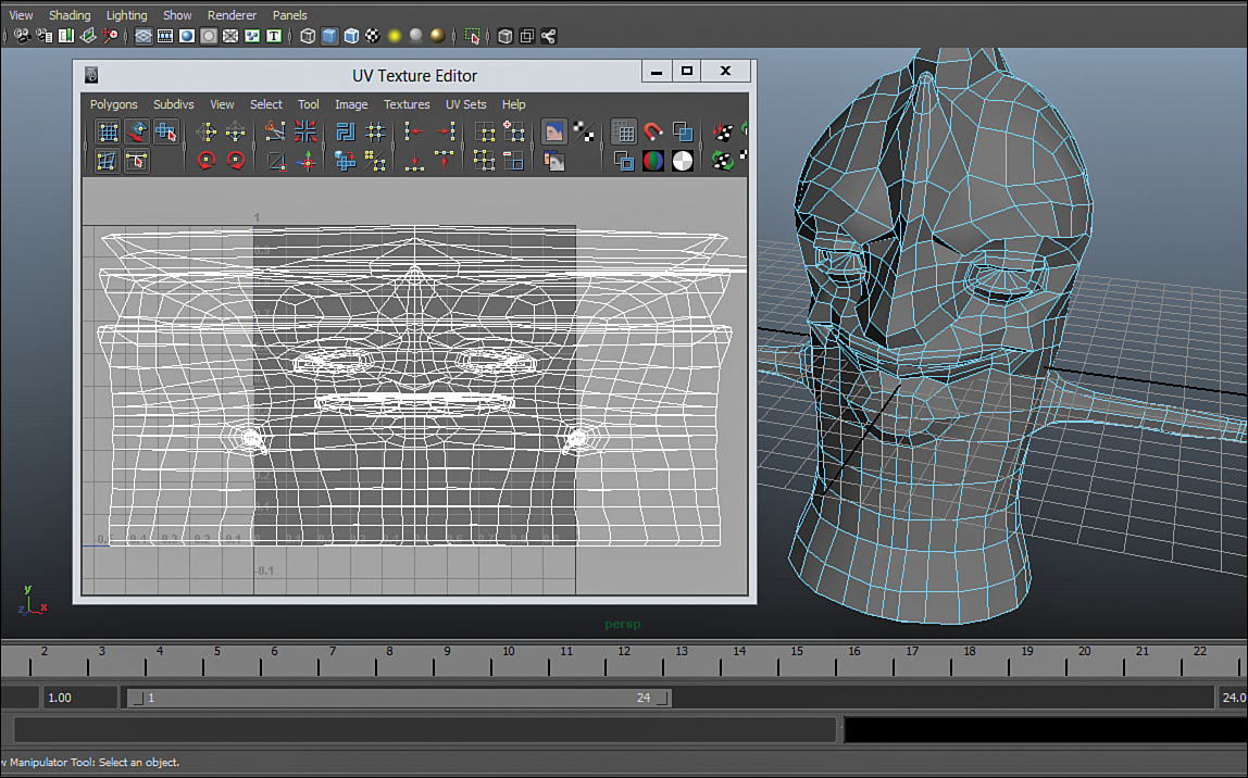
FIGURE 8.29 Don’t worry about what the UVs look like in the beginning. Remember, the workflow is to start with an automatic mapping method and then refine by cutting seams and adjusting UVs.
We will make a seam on each of his arms in the socket where it connects to the body, and a seam along the back of the arm so it can unfold flat. In the Persp panel, select the edges around the connecting point of both arms, select the edge loop at the wrist, and select the edge loop that runs through the center of the back of his arm, as you can see in Figure 8.30. In the UV Texture Editor, go to Polygons, Cut UV Edges.

FIGURE 8.30 The seam we want to create on the arms is selected. This will allow us to unfold these UVs nicely.
Create another seam through the center of the back of his head, and seams around the top horns that protrude outward, using the Cut UV Edges tool. Also, create a seam around the edge loop just inside his lips.
With a little more cutting and sewing, you are ready to Unfold. Select each UV shell by clicking (in the UV Texture Editor) on a vertex and then Ctrl+RMB clicking until you see the option to convert “To Shell.” To unfold the UVs all at once, in the UV Texture Editor, go to Polygons, Unfold. With a little moving, rotating, and scaling, the UVs are complete (see Figure 8.31). Open character_Model_Final.ma to see what the finished product looks like.

![]() Bonus: Character Models
Bonus: Character Models
The Bonus folder for this Hour contains a handful of finished character models for you to open and dissect. Take a look at how each model has edge loops designed to work with the movement of the character. Also, look closely at how many three-, four-, and five-sided faces the characters contain.
Summary
Seeing as a wide majority of visual effects and films contain one if not hundreds of characters, character modeling is a valuable skill in any CG artist’s arsenal. We discussed how to set up a modeling session. We went over bringing in designs as image planes as well as creating symmetrical low-polygon geometry that will be smoothed later. The model started coming to life as we extruded and moved edges. Finally, we combined the two halves and UV’d the character to get him totally ready for skinning.
Q&A
Q. How radically different are modeling workflows for different types of characters?
A. The workflow does not change drastically between highly realistic characters and cartoony characters. The only thing that changes is that most realistic characters are exported to a high-polygon sculpting software after they are finished in low-poly form.
Q. My image planes are not lining up with each other. What is wrong?
A. When this happens, it is because your image planes are not the same size. It is always easiest to take advantage of letting Maya size and position your image planes automatically by making the side and front images have the same dimensions.
Q. When I combine the two halves, and I select all of the center vertices to merge them, they do not all merge. Why?
A. You might have accidentally moved the models, or the center vertices are not exactly lining up with each other. To increase the distance that two vertices will travel to merge together, increase the Threshold value in the Merge command’s option box.
Q. I noticed your character’s eye socket is empty. Shouldn’t we model an eyeball?
A. Remember any object that is not skin tight should be a separate object and not modeled into the character’s model. That goes for eyes and teeth as well. Best bet is to have a sphere in place as you are creating the eye socket to give you a sense of what the eye shape is going to be, and remove it before you are done. Alternatively, you can use that sphere as a good starting point for your eye once the body mesh is complete.
Workshop
The workshop contains quiz questions and exercises to help you solidify your understanding of the material covered. Try to answer all questions before looking at the “Answers” section that follows.
Quiz
1. Why is it important to have orthographic designs when modeling a character?
2. What is the attribute called that adjusts the transparency of an image plane?
3. A copy of a polygon that is mirrored but takes on all of the changes to the original is called what?
4. Name a few areas where good edge loops are important.
5. What is a pole?
Exercise
After this Hour, you probably have many ideas for characters you’d like to create. Try to start with a very simple character and model him or her (or it) from scratch. Avoid starting with a polygon primitive. If you get stuck, open up any of the intermediate files in this Hour’s source files to see how I’ve created my model and then try to follow some of the choices. Do not be too ambitious; if you bite off more than you can chew, you can get stuck—and discouraged.
Answers
1. Drawings with perspective will give a distorted view of a character and make it impossible to follow the designs working in a front or side panel in Maya.
2. The attribute is called Alpha Gain, and it can be adjusted in the Attribute Editor for an image plane. Remember that to see the transparency in the Persp panel, the “renderer” must be set to Viewport 2.0.
3. A “mirrored instance.” This “link” between the polygons is preserved even if you delete history, but not if you combine the two halves.
4. Eye sockets, cheeks, mouths, muscles, and any area that has well-defined, curved detail.
5. A pole is any vertex that is at the intersection of more than four edges. This happens most often when you extrude faces, or have non-four-sided faces in your mesh.