
Hour 4. Modeling with Polygonal Geometry
What You’ll Learn in This Hour:
![]() How to create primitive polygon shapes
How to create primitive polygon shapes
![]() The properties of a polygonal object
The properties of a polygonal object
![]() Traditional polygonal modeling techniques
Traditional polygonal modeling techniques
![]() Preparing a model for texturing and rigging
Preparing a model for texturing and rigging
Like all 3D programs, Maya has incorporated the latest technology as it was discovered, researched, and developed. Interestingly, surface types have gone through many revolutions in the recent past. Starting with polygons, and moving onto splines, then NURBS, subdivision surfaces, and now finally back to polygons, we’ve done a large loop only to end up where we started. Polygons are simple to understand, yet in the beginning of computer graphics, it took far too much computing power to manipulate enough of them to create curved surfaces. Maya’s polygonal modeling tools are top notch, and even more intuitive control is available through MEL scripts and plugins.
Note: Unlocking the Potential of Polygons
Indeed, the number of polygonal modeling tools freely available on the Web is nothing short of amazing. Visit www.creativecrash.com to see an enormous online repository of MEL scripts for modeling and all of the 3D disciplines. You can even download free 3D models for the purpose of looking at the topology and learning how other modelers work.
In this hour, we’ll walk through the process of creating polygonal primitives, and also look at how Maya treats objects’ nodes to get a closer look at geometry creation. We’ll try out many of the modeling tools Maya has, as well as also go over the criteria for a “finished” 3D model.
Objects in Maya
Maya handles objects in a unique way that allows you to separate the information associated with a model. The simplest way to put it is that every object has a transform node, which holds the same information for all objects (3D position, orientation, scale, visibility, and so on) and a shape node, which holds all of the attributes of the object. This can be very confusing to first-time users of Maya, but it doesn’t have to be. Think of it this way: Shape nodes do not have any 3D position and orientation information, until Maya places the shapes into an invisible container and then transforms the container into position in space. When you start working with groups later on, the idea of transform nodes will make more sense. One of the more confusing parts of this concept is that selecting the object in the panel actually selects the transform node and not the shape node. Therefore, it is almost as if when selecting an object, you are not selecting the object itself but rather the invisible group that acts as a container of the object, as you can see in Figure 4.1.

FIGURE 4.1 Displaying shape nodes in the Outliner shows you the relationship between a transform node (pSphere1) and a shape node (pSphereShape1). The transform node actually has the same icon as a group node, so you can think about it like your shapes are in their own personal group by default.
This relationship applies to all objects in Maya, but remember that not all objects are models. A hair system is an object, a dynamic field is an object, even a light is an object (although it has no mesh). Remember, also, that a shape node is not just model data but all of the attributes of an object (for instance, in the case of a light, you have intensity, shadow attributes, and light color).
Creating Polygons
Most 3D programs come with a set of prebuilt shapes, called primitives. Maya is no exception. A common modeling workflow is to begin by creating such a shape and then reshaping and building upon it to make the final model. To access the polygon modeling tools, first switch to the Modeling menu set by selecting it from the drop-down menu list, or by pressing F3. Remember that the first seven menu items in the main menu are not going to change. Also, let’s switch our Shelf to the Polygons shelf by clicking on the Polygon tab on the Shelf. The most common commands and tools are loaded into this shelf for you, as you can see in Figure 4.2.

You will see that the most popular polygon primitives are available in the Shelf for you to create. Clicking on any one of these buttons will bring up the interactive creation tool for the object. Maya will display onscreen instructions on how to create the object depending on the object you are trying to create. Therefore, as Figure 4.3 shows, if you choose to make a cube, you will be prompted to first drag to create the base and then pull up to make the height.
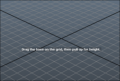
FIGURE 4.3 When you click any of the Shelf buttons to create a primitive, Maya gives you instructions on how to proceed. When I clicked on the “cube” primitive, my instructions displayed in the panel.
The list of objects that can be constructed solely out of primitives is very short. Maybe a hula hoop, a pipe, or a beach ball are simple enough that you can use the built-in shapes, but not much else. We need to start using Maya’s polygonal modeling tools to model objects that have more than rudimentary forms. After you have familiarized yourself with the primitive shapes Maya offers, let’s take a look at the skill of box modeling (a.k.a. polygonal modeling).
Polygons
A polygon is any straight-edged shape with three or more sides, and a polygonal mesh is an object made of multiple connected polygons. A triangle is the simplest polygonal shape, but Maya actually prefers working with four-sided polygons. You will find that the polygon primitives are largely formed of four-sided polygons by default. Although Maya supports polygons with any amount of sides, you will be introducing headaches down the road if you do not stick to clean, three- and four-sided polygons when you are modeling. Figure 4.4 illustrates the different types of polygons you can create in Maya.

FIGURE 4.4 A three-sided, four-sided, and twenty-sided polygon. Generally, we want to stick to three- and four-sided polygons when modeling in Maya.
Let’s begin to dive into the modeling tools Maya has to offer. We will use the most common tools to create a polygonal mesh of a hammer, starting from a single polygon and working all the way up to a finished model.
Sometimes the easiest way to begin a mesh is with a single polygon. You may notice we could get to a further-along starting point by using one of the polygon primitives, but we’ll save that knowledge for later. You will definitely want to start from a primitive that is close to your end goal when you are working in the future.
Polygon Plane
Using the Polygon shelf tools, we can create a polygon primitive by selecting the Polygon Plane button ![]() we can drag on the grid to get, as shown in Figure 4.5.
we can drag on the grid to get, as shown in Figure 4.5.
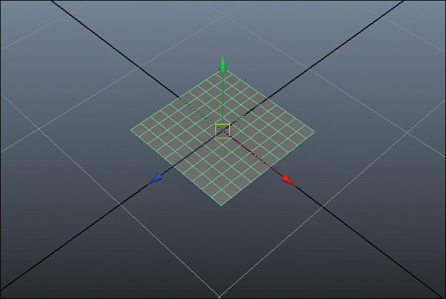
You will notice that the plane is made up from a large number of four-sided polygons, but we do not actually need that many. When modeling, it is usually best to keep the number of polygons to the minimum required for the task to avoid overcomplicating things. More polygons can be added later on, if needed. To remove the extra polygons, make sure the plane is still selected and expand the INPUTS section in the Channel Box (right area) by clicking on the label polyPlane1. This reveals the attributes of the pPlane1 shape node to specify the width, height, and how many subdivisions are required. The number of polygons our mesh is made from is dependent on how many subdivisions are specified. Because we want to keep the mesh complexity to a minimum at this point, set the subdivision height and width to 1, as shown in Figure 4.6.

FIGURE 4.6 The plane with one subdivision, reduced from four polygons down to what we need to begin our mesh.
Tip: Wireframe and Shaded Mode
To view your models as just a wire mesh made up of your mesh’s edges, press the 4 key on your keyboard. To see the geometry shaded smoothly in the panel, press the 5 key. (The 6 key and 7 key display your objects as textured and with lights, respectively, but it is normal to stay simply in smooth-shaded mode when modeling by pressing 5.)
Components
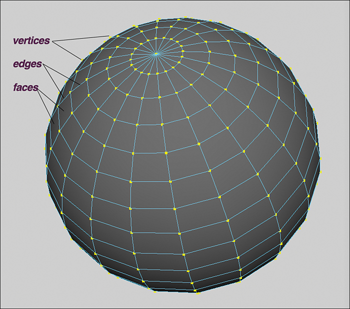
In order to create models, you will be manipulating several different types of components that make up polygonal meshes. Before we start modeling, let’s look at the different component types of a polygon mesh, displayed in Figure 4.7. The component parts of a mesh that are able to be manipulated in panel are as follows:
![]() Vertices—These are 3D points that define a mesh.
Vertices—These are 3D points that define a mesh.
![]() Edges—These are the lines that connect the vertices.
Edges—These are the lines that connect the vertices.
![]() Faces—When at least three edges connect together at their endpoints, Maya creates a surface between them. This is called a face, or sometimes a polygon.
Faces—When at least three edges connect together at their endpoints, Maya creates a surface between them. This is called a face, or sometimes a polygon.
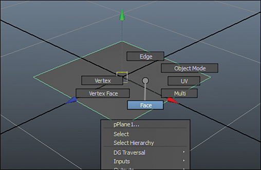
Maya makes it simple and easy to access a mesh’s components. The first way is to press F8, which takes you into component mode. If you don’t have a type of component already selected, you will be brought into vertex mode. The second way to access the vertices is to RMB click and hold on the object you want to manipulate, and then drag the cursor to the component you need, as shown in Figure 4.8. The last way to access the components is to use the menu bar, select component mode, and then choose the component type or types you would like to access, as shown in Figure 4.9. All these methods give you the same access, although probably the RMB method is the most widely used (and easiest). No matter what method you use, pressing F8 again is always the fastest way to return to object mode so you can select and manipulate your meshes rather than components.

Extrude
Extruding faces and edges is one of the most fundamental ways to create polygonal geometry. The Extrude tool creates new faces and edges from the selected components. Access Extrude and the other main modeling tools by making sure the Polygon menu set is active (F3) and going to the Edit Mesh menu. To actually extrude the face or edge, you need to select it first. Using our plane as an example, go into component mode (F8) to select faces. Select the plane’s face and use the blue manipulator arrow to pull the face upward, like I did in Figure 4.10.

FIGURE 4.10 The polygon extruded upward in space. We are beginning to create the handle of our hammer.
The Extrude tool allows you to drag the extruded face by using the normal transform manipulator you are used to seeing with the Move and Scale tools, or you can use the sliders for Thickness, Offset, and Divisions to get different results. (Note that the Edit Mesh menu has been torn off.)
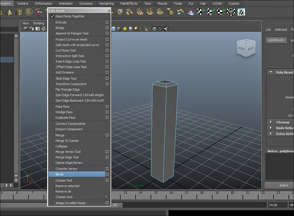
Bevel
Bevel is another of the most basic tools when working with polygons. It divides the selected geometry and creates an angle between the faces. If we select all the top edges and bevel them using the Bevel tool from the Edit Mesh menu, we can create the grip of the hammer. Figure 4.11 shows the top face of the hammer beveled inward, which starts to give us the shape that will turn into the grip.
Insert Edge Loop
The Insert Edge Loop tool is very powerful. It creates a loop of edges to your model, adding a level of detail wherever you need it. To use it, select Insert Edge Loop from the Edit Mesh menu and then click-drag on an edge to place the new edge loop where you want it. With good modeling technique, you’ll find this tool to be one of the most useful in your arsenal. To add detail to the hammer, insert an edge loop to the top section of the hammer, as I have done in Figure 4.12.

FIGURE 4.12 An edge loop has been added to this top part of the hammer. We will scale and translate this edge loop to make it cleaner.
As we continue to extrude faces, we get more polygons and therefore more detail in the mesh. We can then select the new faces and translate, rotate, and scale them to make our hammer take shape. Wherever we need extra detail, the Insert Edge Loop tool can normally provide the needed resolution on the mesh. As you can see, the most common workflow for polygonal modeling includes a lot of switching tools. We commonly go back and forth between creating new geometry and detail with tools such as Extrude and then adjusting the new polygons by using the Move, Rotate, and Scale tools on the mesh’s components. See how the hammer form is starting to emerge in Figure 4.13.

Subdividing
When you render a polygonal object, it is common that you will want to have a much more detailed model than you could ever create by hand. To give some perspective, the hammer in Figure 4.13 is made out of a paltry 50 polygons. Many feature-film-quality models are tessellated at render time to produce a scene with upwards of 5 million polygons. Because it would be impossible to hand-extrude, bevel, move vertices, and add edge loops to get that level of detail, Maya has built-in polygonal smoothing tools. The main consideration is whether you want the tessellation to occur at render time after the scene is complete or you need to apply more edits, deformers, and manipulations to an already smoothed model. For the former, we will use the Mental Ray smooth mesh preview. For the latter, we will use Mesh, Smooth.
Note: Timing Matters
Maya keeps what’s called “history” on the models. This is a record of the edits made to an object. If you apply a Smooth to a mesh and then make edits such as moving vertices or faces, these edits are dependent on the results of that Smooth—meaning you cannot change the parameters of the Smooth without unpredictable results to your mesh. This is because the Smooth is before the mesh edits in the history of the mesh. We’ll talk more about this in future Hours.
Smooth
To smooth a mesh, we simply go to the Mesh, Smooth command. This command has many options that alter the outcome of the model, but for now we’ll simply adjust the number of divisions to get a feel for changing parameters. We’ll also use the Attribute Editor for the first time. With the Smooth applied, we’ll load the attributes. Pressing Ctrl+A with an object selected brings up the Attribute Editor, as well as loads tabs across the top that correspond to that object’s inputs. Many of the commands and tools you use to create a model will load into tabs here as well. Some of the inputs may even offer settings that you can change to get different results (see Figure 4.14).

FIGURE 4.14 The Smooth is applied, and we are viewing the nodes connected to the hammer. The attributes of the Smooth are accessed by clicking on the appropriate tab at the top. Sliding the Division Levels slider will give us more or less detail, as we see fit.
Remember that because an object has history, you cannot make changes to a node that other nodes depend on without potentially disastrous results. However, if you are happy with the amount of smoothing you’ve achieved, you can remove all of the history of a model by choosing Edit, Delete by Type, History (or by pressing Alt+Shift+D).
Once you have hit the limit of your Undo queue, or close and open a scene again, deleting history cannot be undone. You should be sure that you will not have to make any edits to the construction history before doing so. As unpredictable as editing nodes deeper in history can be, there are actually instances in which making such edits is necessary and in fact part of the process, such as with rigging characters, texturing objects, and manipulating dynamics.
Smooth Mesh Preview
Instead of using the Mesh, Smooth tool, we can preview our smoothing in the panel. Pressing 3 with a piece of geometry selected activates the Smooth Mesh Preview. Maya will show you, in the panel, the amount of tessellation that will occur at render time. The advantage of this method is you can continue working on your low-poly mesh and then check the final result by pressing a single key. Pressing 1 takes you back to the base mesh, whereas 2 shows you both. You can change the amount of tessellation that you see in the Attribute Editor by navigating to the object’s Shape Node tab and finding the Smooth Mesh expanding menu.
Crease
The last top-level tool we’ll look at with polygonal modeling is the Crease tool. This powerful tool allows us to define hard edges on our model, making it so that when we use Smooth Mesh Preview, areas of detail are not lost. Go to Edit Mesh, Crease Tool to load the tool. The tool only works on edges, and to increase the hardness, simply select an edge and MMB drag, as I am doing on the hammer in Figure 4.15.
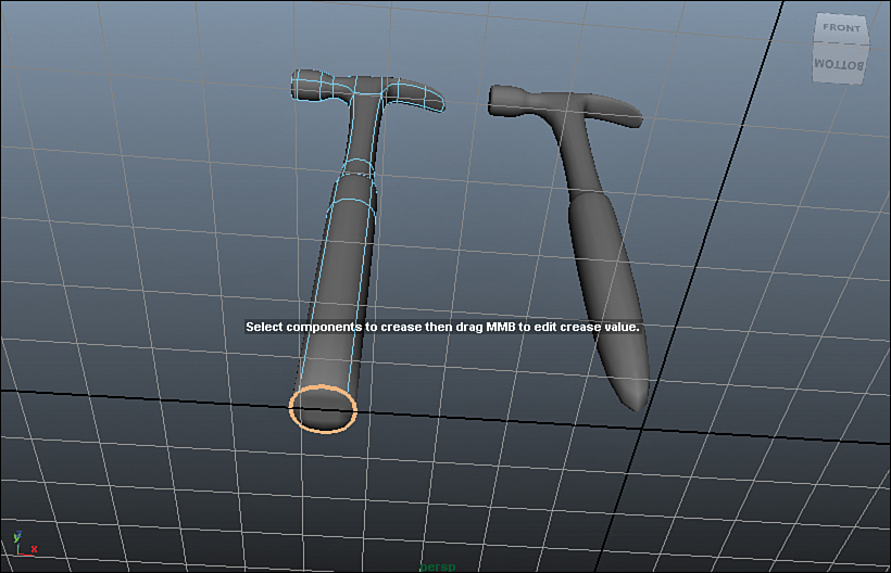
FIGURE 4.15 The difference between a creased edge loop and a non-creased edge loop on the bottom of our hammer mesh. Using creases to create hard edges as opposed to having edges really close to each other saves on modeling time.
Take a look in this Hour’s source files and you will notice a few extra completed models you can look at. These can be used in your animations if you wish, or you can continue to refine and edit these models to make them your own.
Summary
In this Hour, you learned how Maya handles objects in scene files, and we created a few standard primitive shapes. We then started with polygonal (box) modeling and explored the use of tools Maya has to offer. Once a mesh is complete, you can smooth it now with the Mesh, Smooth command, or you can smooth it later by pressing 3 with the object selected and using Maya’s Smooth Mesh Preview function.
Q&A
Q. Do I have to start from a primitive?
A. No, but it is easiest to start from a primitive. Most people start from a box if they are doing polygonal modeling. If you want to create a single polygon, you can use the Create Polygon tool in the Mesh menu, but it takes more clicks than it would to start from a plane anyway.
Q. I have many different objects. Can I combine them into one?
A. Yes, with all of the objects selected, go to Mesh, Combine. You should note, however, that unless the vertices have been merged together on the seams of the objects after everything has been combined, the surface will not be smooth after you combine the objects. Combining should be viewed almost the same as grouping objects.
Q. I want to extrude faces that are next to each other, but they are connected by their shared edge. How do I fix this?
A. At the top of the Edit Mesh menu is a check box called Keep Faces Together. Unchecking this means that every single face that is extruded will not share any edges with any other polygon, even if they are adjacent.
Q. I created a mesh, but all of the edges appear hard and angled even though they flow into one another very smoothly. What’s wrong?
A. Faces have something called “normals,” which are basically the angle that Maya considers to be the “front” of the face. When two normals are far apart enough in angle, Maya draws the edges they share as a sharp edge. When you are box modeling, though, Maya doesn’t calculate this value and therefore considers all new edges as “hard.” To make your mesh smooth again, go to Normals, Soften Edge (or Harden Edge), with the edges you want softened (or hardened) selected.
Workshop
The workshop contains quiz questions and exercises to help you solidify your understanding of the material covered. Try to answer all questions before looking at the “Answers” section that follows.
Quiz
1. How many sides must a polygon have?
2. Name two ways to access an object’s components.
3. The Extrude tool is found under which menu?
4. What is a series of unbroken edges called?
5. Why is using the Mesh, Smooth command an issue if you want to make further changes to an object?
Exercise
Choose a few simple models to create. Start from primitives with objects that might lend themselves to simple shapes, such as a cup or a wheel. Then move on to more complex shapes and extrude and manipulate the polygons by hand. Try modeling a simple spaceship, a chess piece, or another interesting prop. Don’t move on to characters until you’ve read through Hour 8, “Character Modeling.”
Answers
1. At least three. Polygons can have ostensibly an infinite number of sides, but Maya likes rendering objects that have three- or four-sided faces.
2. You can press F8 and then choose the component type you want to manipulate in the top menu bar, or you can RMB click and drag to get a marking menu that will let you decide.
3. Like all of the component-level and box-modeling tools, Extrude is found under the Edit Mesh menu.
4. A series of unbroken edges is called an “edge loop.” When an edge loop hits a vertex that has more than four edges going into it, the edge loop might be broken though. You will learn more about why edge loops are important in Hour 8.
5. Using a Smooth adds the command into the object’s history, which means if you want to do further edits but do not want to work on the tessellated model, you have to first remove the Smooth node by deleting it and then add it later. An easier way to get a good preview of the smoothing is to press 3 and see the Smooth Mesh Preview.