
Hour 5. Modeling NURBS Curves and Surfaces
What You’ll Learn in This Hour:
![]() What NURBS curves and surfaces are
What NURBS curves and surfaces are
![]() How to create simple NURBS geometry
How to create simple NURBS geometry
![]() How to utilize NURBS’ properties for good results
How to utilize NURBS’ properties for good results
![]() What other uses NURBS curves have in Maya
What other uses NURBS curves have in Maya
3D graphics went through some very rapid change in the beginning. One of the most tumultuous areas of development was that of surfacing and geometry. The very earliest representation of a surface was a polygon. Other surface types and ways of rendering objects came and went quickly. Splines, voxels, point clouds, and subdivision surfaces all have their pros and cons. When NURBS first came about, apart from having a funny-sounding name, they were all the rage. Although they do not offer much benefit as a primary surfacing technology with today’s technology of extremely high polygon tools, they are still very useful for specific purposes.
Note: Getting Terminology Straight
Maya calls any NURBS curve simply a “curve.” In some menus, Maya will refer to a surface created from curves as a “surface” and sometimes as “NURBS,” such as in the Edit, Convert menu. Although other 3D programs might have more than one type of spline technology, you should know that even though Maya sometimes drops the word “NURBS,” we are still dealing with this technology whenever we use “curves” and “surfaces” within Maya.
In this Hour, you will get an overview of splines and how to create simple geometry using them. In addition, we’ll look at what inherent properties of NURBS can be utilized to our benefit. We’ll also walk through some of the most common uses for NURBS and how to manipulate them correctly for these purposes.
What Are NURBS?
The acronym stands for Non-Uniform Rational Basis Spline. Knowing the mathematics behind the equations that represent B-splines is not required to understand how they function in Maya (although you will be happy to know that mathematically, these curves are pretty versatile, stable, and fast to compute). It is interesting to point out that NURBS are not actually renderable surfaces; instead, they are tessellated at render time and made into polygons. The real power of NURBS and the reason they were en vogue in the late 1990s and early 2000s was because of the ease of creating and manipulating perfectly smooth surfaces. You see, up until that point, the other paradigms offered only cumbersome control over smooth surfaces, or traded intuitive control for the resolution of the geometry. NURBS seemed to offer the best of both worlds.
Curve Components
A NURBS curve is made up of edit points and control vertices (see Figure 5.1). Edit points are points on the curve that the curve passes through. Control vertices (CVs) are like handles that influence a NURBS curve, and they provide a more reliable way to adjust the shape of a curve. CVs are automatically created in between edit points when you make a curve.
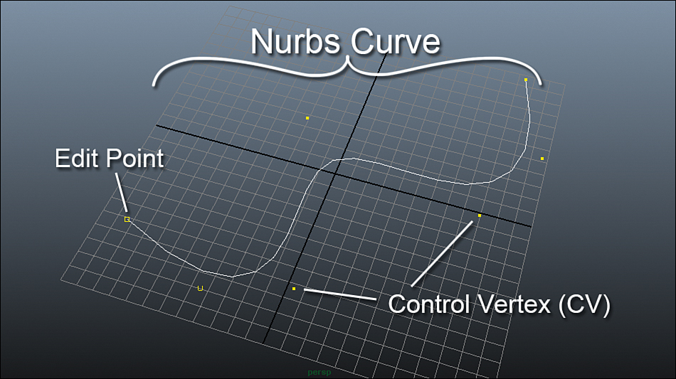
FIGURE 5.1 The components of a NURBS curve. Edit points lay directly on the curve, whereas CVs act like handles that “pull” the curve in different directions.
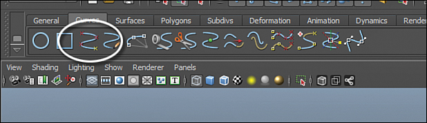
To create a NURBS curve, use the EP Curve tool. This is available by clicking on Create, EP Curve Tool when you have the Surfaces menu set loaded (F4). In the Curves shelf, the EP Curve tool is also prominently featured (see Figure 5.2).
Curves are parametric, meaning that they have a direction and along their path we can assign a value from 0 to 1. To put it another way, a curve’s start point is always a value of 0 and the end point is always a value of 1, no matter the size or shape of a curve. Their direction is important when you’re creating surfaces from two or more NURBS curves, because the surface will “stretch” between the same parametric values on each curve as it is drawn: 0 will connect to 0, 1 will connect to 1, and so on. Let’s take a look at this, and at the same time, learn the components of a NURBS surface.
Surface Components
When a surface is created using curves (shown later in this Hour), the surface takes on some of the properties of the curves. The surface direction, the number of surface control points, and of course the shape are derived from the splines. You can see the components that make up a surface in Figure 5.3. In a similar fashion to polygonal modeling, NURBS modeling involves planning the flow of edges (in this case, splines). Some people call a surface a “patch,” due to the fact that creating a character or complex object will require many surfaces to be “stitched” together, almost like a patchwork quilt. A very complex model might be made up of dozens of patches, created so that the geometry blends nicely from one patch to another. A surface will have control vertices (CVs) on its surface that behaves the same way they do on a curve. The placement of surface CVs is determined at creation time; therefore, in order to adjust the level of control, a surface needs to be rebuilt. We’ll take a look at this procedure too.

FIGURE 5.3 A NURBS surface. The curves used to create this surface are selected. Notice the CVs on the surface that are generated automatically.
Tip: Keeping an Eye on CVs
Because control vertices determine pretty much the entirety of a surface’s shape, I like to keep an eye on them without having to switch to component mode. With a surface selected, go to Display, NURBS, CVs and they will always be visible. Now as you work with the surface, you can troubleshoot at a glance.
A surface is made up two types of splines. The splines that run parallel to the direction of the creation curves are called “spans.” The splines that cross the spans are called “isoparms.” Isoparms are created where, due to the math that creates a NURBS curve, a new interior section needs to be created to continue the surface. You do not need to worry about the math or know how and why isoparms are created, only that adding resolution within a surface is a matter of adding and subtracting isoparms to and from your surface. Also know that the CVs you will use to manipulate the interior of a surface are created along isoparms, as you can see in Figure 5.4.
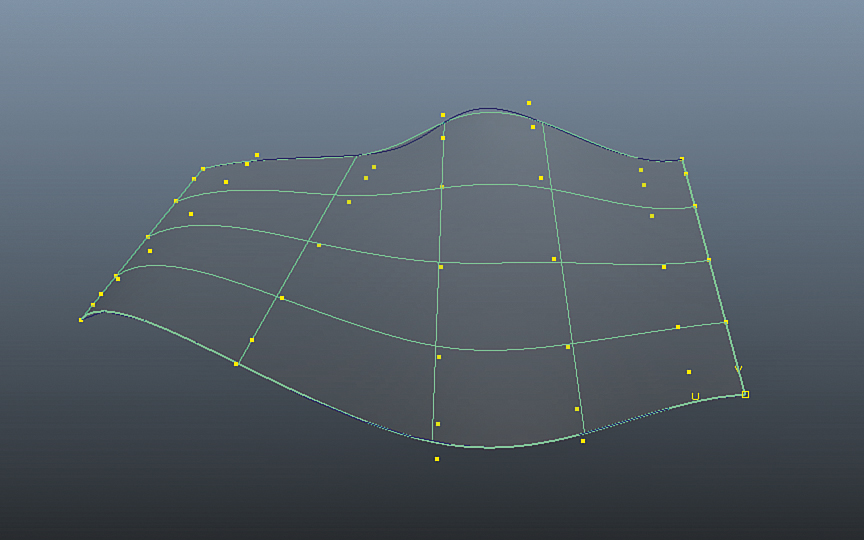
FIGURE 5.4 The NURBS surface has multiple isoparms that give us the resolution we need to adjust the surface however we’d like.
Creating complex geometry can be very cumbersome, so it’s best to think of the simplest method to achieve the shape you want rather than create all of the small details with curves themselves. In other words, you should rely a little bit on your ability to adjust surfaces after you create them.
Modeling with NURBS
Some pretty complicated structures can be created using the surface tools Maya has to offer. In general, you will be concerning yourself with finding logical seams in the model, almost like UV’ing polygons. Think of NURBS as patches on a quilt that is stretched over your model. In stark contrast to polygons, NURBS have UVs built in already, so you do not have to worry about applying UVs to your NURBS model when you are done creating it.
Note: History in the Making
NURBS keep construction history like every surface type in Maya. The interesting thing about NURBS history is that it preserves very nicely throughout the creation process. The danger in this, however, is that you can make changes to a surface by manipulating the CVs of the curve that generated the surface, the position and orientation of the curve itself, or the surface CVs on the generated surface. In fact, there are still more ways to change the resulting model. You have to be very careful when modeling with NURBS to try to make changes on the lowest level you can to preserve the predictability of your results.
Creating a Simple Surface
We’re going to create a surrealist checkerboard. Our model will be complete with a wavy checkerboard and a pawn floating above it.
First, we’ll create two sides of the checkerboard. Remember, Maya automatically creates the detail within the surface (and it can also be rebuilt automatically with greater or lesser detail anyway), so our workflow will be to just create the simple shape. Using the EP Curve tool, draw two squiggly curves on the grid. Clicking on the grid will add an edit point, and pressing Enter will finish the curve (see Figure 5.5).

FIGURE 5.5 Our two curves. We don’t care what their shape is, but you should create the curves in the same direction.
With our two curves created and selected, we will have Maya create a NURBS surface between them. A few tools can be used to achieve this, the simplest being the Loft tool. This is found under Surfaces, Loft. This tool basically grafts a surface from one curve to another. The nice thing about this tool is that it creates a surface that is parametric regardless of the shape of your curves, or if your curves have a different number of edit points. You can adjust the accuracy of the created surface later as well. See Figure 5.6 for an example of a lofted surface.
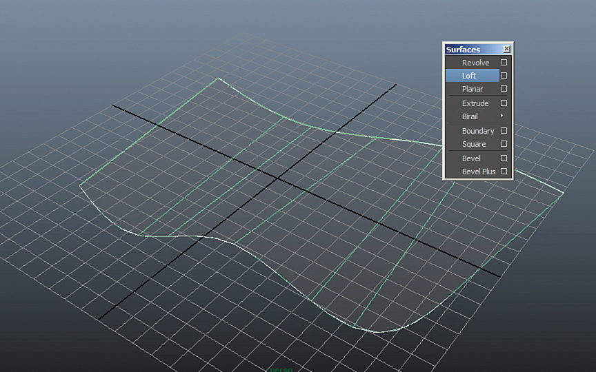
FIGURE 5.6 The Loft tool applied to the two NURBS curves. A surface is drawn between the curves. Note the spans are on the outside, and cross-section isoparms are generated across the surface.
Our surface needs to be rebuilt so that it has an even amount of detail spread across it. Maya knows how to create a new surface from this one that has evenly distributed isoparms—and therefore CVs for us to manipulate. By clicking on Edit NURBS, Rebuild Surfaces, we will get the result shown in Figure 5.7.
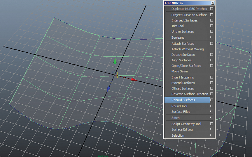
FIGURE 5.7 The Rebuild Surfaces tool applied to our NURBS surface. Notice how we have uniform distribution of our isoparms and therefore will get easy adjustment of the surface now.
Note: Continuity
Keep in mind that if you are going to be creating a model made from multiple surfaces, the resolution needs to be uniform so that the surface appears to be smooth, continuous, and seamless. The Rebuild Surfaces tool has many options and parameters that allow the artist to control the end result. Although we’re using the default parameters right now, this tool is worth exploring further when you move on to complex models.
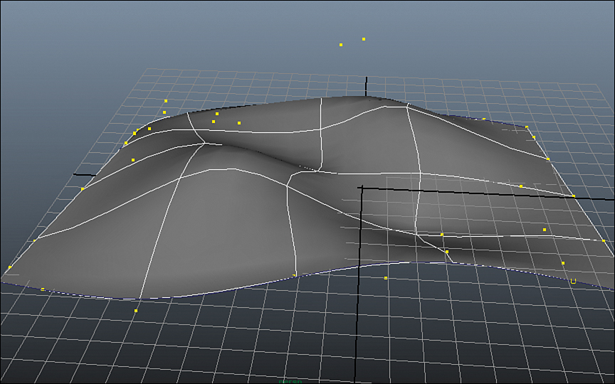
Now by RMB dragging on the surface and choosing the CVs component mode, we can manipulate the surface. Drag the CVs up and down to make an interesting wavy surface (see Figure 5.8).
Now we can create our pawn. A great tool for creating shapes that are symmetrical about a point is the Revolve tool. It creates a surface by rotating the curve and extruding the surface along the resulting path—perfect for glasses, vases, table legs, or, in this case, a chess piece. Create the outline of our pawn in the side panel with the EP Curve tool. The center of the grid will be the point of rotation, so keep it centered like I have in Figure 5.9.

FIGURE 5.9 The profile of our pawn created in the side panel. Remember that because NURBS keep their construction history nicely intact, we can always adjust this original curve to get a nicer result if the revolved surface doesn’t turn out exactly how we expect it to.
There are a few corners that I would like to make creased. The curved ridges in the side of the pawn should be hard edged, for example. You could always create more CVs by using the Insert Knot tool and then position them very closely, but in general it’s a better idea to work with as few controls as possible to get the result you are looking for. Therefore, we’ll instead use the CV Hardness tool. Go into CV component mode by RMB dragging on the curve. Select the CVs you want to be hard and then go to Edit Curves, CV Hardness. If it doesn’t work, redraw your curve with more edit points to begin with (the tool requires that you have at least one CV on either side of the CV you are hardening that is not next to an edit point). Figure 5.10 shows the before and after of using the CV Hardness tool to get a crease in my curve.
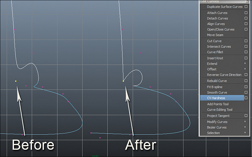
FIGURE 5.10 The CV in the corner before and after using the CV Hardness tool on it. Remember, you need to have enough edit points in your curve to use this tool. If hardening a CV does not work, redraw your curve with more edit points.
Now that the curve is cleaned up and ready to revolve, we’re going to do just that. Select the curve and click Surfaces, Revolve, as shown in Figure 5.11.
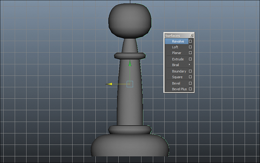
FIGURE 5.11 The newly created revolved surface. The default options work fine for us here because the surface is revolved around the Y axis 360 degrees.
Maya made quick work of that model! We are not done yet, though. If you look at the top of the model, you will see it has a hole in it. Switch to isoparm component mode by RMB clicking and dragging upward and then select the hole like I did in Figure 5.12.
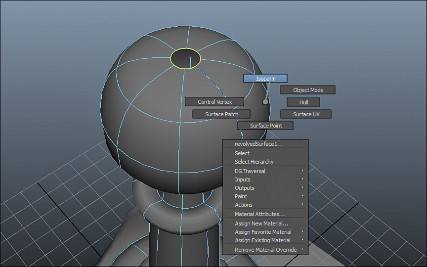
FIGURE 5.12 The hole in our revolved surface has an isoparm as its boundary. Choosing Isoparm and selecting it allows us to create a new surface to fill this hole.
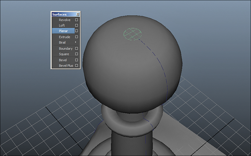
Now click on Surfaces, Planer. A flat surface fills the hole (see Figure 5.13).
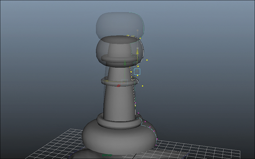
Adjusting the Model’s History
We already have a good-looking pawn, so let’s make a few adjustments and see the results in real time. Remember that construction history with NURBS is very powerful and intuitive. If we move the curve that we revolved, it will actually update the resulting surface. In fact, the planar cap that we just created will grow to cover the new sized hole as well. It’s very easy to make adjustments to your NURBS model after you have created the basic structure. That is why it is good workflow to get your simple structure in place and make adjustments later to refine your model. I’m going to make the pawn a little fatter by transforming the curve away from the center gridline, and I’ll shorten it by bringing down the top CVs, as shown in Figure 5.14.
Tip: Many Ways to Get the Same Result
Once again, I chose to make my adjustments on the lowest level I could when modifying this model. Rather than scale the resulting surface or adjusting its CVs, I modified the source curve for the revolve. I will continue to make adjustments at this level for as long as I can.
Now that we have our chess piece and chessboard, let’s throw some simple textures on them and put everything together.
Because NURBS have UVs built into their structure, all we need to do is apply the texture maps we want and we’ll be done. We will create a Blinn by RMB clicking on the surfaces, choosing Assign New Material, and then clicking on Blinn. In the Attribute Editor that opens, apply a Checker texture to the Color attribute. Apply a Blinn to the pawn as well, this time using just black for the color attribute. Once all that is done, position and scale the pawn to look like it’s floating above the surreal chessboard, and the image is complete (see Figure 5.15).
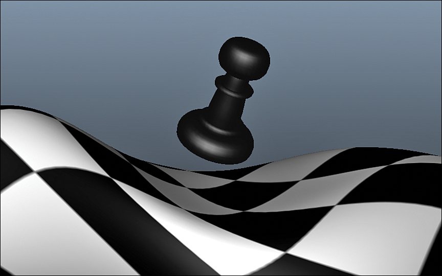
FIGURE 5.15 The final composed scene. The pawn surface has been moved and scaled to be in the position that I want.
Now that I am sure my image is ready to compose, I can select the end resulting surface of the pawn and move it where I want it. If you are following along in your own scene or have opened the file “05 - Curves and Surfaces.mb” included in this Hour, then see what happens when you edit the curve. It still affects the final pawn surface. This will affect it until you delete the history on the model, so it’s a good idea to stay organized in your scene file in regard to where you are creating your NURBS geometry. Things can quickly get very messy and you may lose the ability to nicely edit your NURBS surface history.
More Uses for Curves
Curves are not just useful for modeling. They have a variety of other uses. Some of the most common uses for curves are for animation controllers, path animation, particle paths, and more. Let’s take a look at a few of these uses.
Animation Controllers
Included in this Hour’s files is Josh Burton’s awesome character rig “Morpheus.” If you open that file, you will see a professionally created character rig, complete with NURBS curves that act as controllers for the body parts. NURBS are chosen because they are clearly visible yet do not get in the way of seeing the body because they are basically wires. They also do not render. See Figure 5.16 for an example of control curves on an animation rig.

FIGURE 5.16 This character rig uses NURBS curves for the controllers. They are easy to see but don’t get in the way.
Path Animation
We can also use curves to create paths for our objects to follow. Because NURBS curves are parametric, Maya allows us to animate an object that travels from the start (U value of 0) to the end (U value of 1) of a curve. This is very powerful and used widely in production. Let’s set one up so you can quickly get a feeling for this powerful animation tool.
Create a new scene, create a polygonal sphere, and then create a NURBS curve of any shape, as shown in Figure 5.17.

FIGURE 5.17 Our pShere1 and curve1 are going to work together to make a path animation in a few easy steps. Don’t forget you can either use the Create menu or the Shelf to create these shapes.
Now select pSphere1 and Shift-select curve1. Switch to the Animation menu set by pressing F2 and then click on Animate, Motion Paths, Attach to Motion Path, as shown in Figure 5.18.
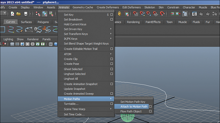
FIGURE 5.18 The sphere is now attached to the motion path. Maya creates an animation curve on the sphere by default that you can adjust easily in the graph editor. We will go over that in Hour 13, “Animation: Adding Movement to Your Scene.”
If you press Alt+V, the animation will play back and you can watch the sphere move along the path of the curve, as shown in Figure 5.19. Just like all other functions in Maya, this operation saves history. If you manipulate the path, the sphere will continue to move along the new path.
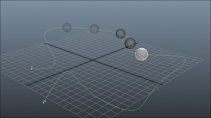
FIGURE 5.19 The sphere moving along its path. The four past frames are ghosted to show the direction of the moving sphere. Remember, you can change this path at any time and the animation will update in real time.
You’ll find some more NURBS models waiting for you in the Bonus folder for this Hour. Included are a nice chess board and some more chess pieces for you to work with. When you get to the Exercise, use these models as a reference to start from.
Summary
We took a look at the very powerful NURBS geometry type in Maya. First, we discovered the components that make up a NURBS curve. We then found the same components in a NURBS surface. We created a simple NURBS surface using the EP Curve tool and the Loft tool. Then we created a NURBS pawn by making a curve to represent the object’s profile and using the Revolve tool. NURBS have more than just modeling applications, though. Because of their high visibility, low scene overhead, and how they don’t block geometry substantially, we saw a finished character rig that makes ample use of NURBS objects as controllers. One last example of a good application of NURBS curves is as a path for an object to follow in an animation.
Q&A
Q. What are the downsides to NURBS?
A. NURBS are not widely used for characters in feature film and visual effects because of the advent of polygonal modeling tools that can handle immense amounts of detail. They do not deform as nicely as polygons do, and can be tricky to make appear seamless.
Q. Why can’t I use a certain NURBS tool on my curves?
A. Some of the tools have specific requirements for them to work. Bevel needs a closed curve or two curves; it won’t work on a straight, open NURBS curve. Look at the Command Line for feedback as to what the requirements are for the tool you are trying to use.
Q. Even when I create the curves in a clean way, the surfaces don’t seem to be seamless. Why?
A. This is one of the more difficult aspects of NURBS. In order for there to not be a visible seam, the edges your surfaces need to have tangents that are parallel. Maya does not have automatic tools that will adjust the continuity for you, but modeling tools do exist that help with maintaining a perfectly smooth appearance across multiple NURBS curves. For further information on how NURBS surfaces fit together, do a search on the Web for “G1 continuity.”
Workshop
The workshop contains quiz questions and exercises to help you solidify your understanding of the material covered. Try to answer all questions before looking at the “Answers” section that follows.
Quiz
1. What does NURBS stand for?
2. True or false? NURBS need to be UV’d after creation.
3. Cross-sections of a NURBS surface are called what?
4. Which curve creation tool is in the Curves shelf—the CV Curve tool or the EP Curve tool?
5. The Revolve tool revolves the curve around which axis by default?
Exercise
Model an entire chess set using the tools we discussed in this Hour. The Revolve tool is perfect for nearly all of the pieces. You may have to get a little tricky with the Bevel, Trim, and Loft tools when it comes time to make the Bishop and Knight.
Answers
1. Non-Uniform Rational Basis Spline. A basis spline is a form of Bezier spline, and you may hear people refer to NURBS as such.
2. False. They have UV information built into them inherently.
3. Isoparms. Adding Isoparms adds CVs to a surface as well.
4. The EP Curve tool. This tool allows you to place edit points exactly where you want them in the grid.
5. The Y axis. Our pawn was revolved like a spinning top. You can change this by going into the tool’s option box ![]() .
.